EP0904963A2 - Conditionneur d'air pour véhicule automobile - Google Patents
Conditionneur d'air pour véhicule automobile Download PDFInfo
- Publication number
- EP0904963A2 EP0904963A2 EP98202900A EP98202900A EP0904963A2 EP 0904963 A2 EP0904963 A2 EP 0904963A2 EP 98202900 A EP98202900 A EP 98202900A EP 98202900 A EP98202900 A EP 98202900A EP 0904963 A2 EP0904963 A2 EP 0904963A2
- Authority
- EP
- European Patent Office
- Prior art keywords
- heat exchanger
- compressor
- valve
- air conditioning
- conditioning system
- Prior art date
- Legal status (The legal status is an assumption and is not a legal conclusion. Google has not performed a legal analysis and makes no representation as to the accuracy of the status listed.)
- Withdrawn
Links
Images
Classifications
-
- B—PERFORMING OPERATIONS; TRANSPORTING
- B60—VEHICLES IN GENERAL
- B60H—ARRANGEMENTS OF HEATING, COOLING, VENTILATING OR OTHER AIR-TREATING DEVICES SPECIALLY ADAPTED FOR PASSENGER OR GOODS SPACES OF VEHICLES
- B60H1/00—Heating, cooling or ventilating [HVAC] devices
- B60H1/00642—Control systems or circuits; Control members or indication devices for heating, cooling or ventilating devices
- B60H1/00814—Control systems or circuits characterised by their output, for controlling particular components of the heating, cooling or ventilating installation
- B60H1/00878—Control systems or circuits characterised by their output, for controlling particular components of the heating, cooling or ventilating installation the components being temperature regulating devices
- B60H1/00899—Controlling the flow of liquid in a heat pump system
- B60H1/00907—Controlling the flow of liquid in a heat pump system where the flow direction of the refrigerant changes and an evaporator becomes condenser
-
- B—PERFORMING OPERATIONS; TRANSPORTING
- B60—VEHICLES IN GENERAL
- B60H—ARRANGEMENTS OF HEATING, COOLING, VENTILATING OR OTHER AIR-TREATING DEVICES SPECIALLY ADAPTED FOR PASSENGER OR GOODS SPACES OF VEHICLES
- B60H1/00—Heating, cooling or ventilating [HVAC] devices
- B60H1/00642—Control systems or circuits; Control members or indication devices for heating, cooling or ventilating devices
- B60H1/00814—Control systems or circuits characterised by their output, for controlling particular components of the heating, cooling or ventilating installation
- B60H1/00878—Control systems or circuits characterised by their output, for controlling particular components of the heating, cooling or ventilating installation the components being temperature regulating devices
- B60H1/00899—Controlling the flow of liquid in a heat pump system
- B60H1/00914—Controlling the flow of liquid in a heat pump system where the flow direction of the refrigerant does not change and there is a bypass of the condenser
-
- F—MECHANICAL ENGINEERING; LIGHTING; HEATING; WEAPONS; BLASTING
- F25—REFRIGERATION OR COOLING; COMBINED HEATING AND REFRIGERATION SYSTEMS; HEAT PUMP SYSTEMS; MANUFACTURE OR STORAGE OF ICE; LIQUEFACTION SOLIDIFICATION OF GASES
- F25B—REFRIGERATION MACHINES, PLANTS OR SYSTEMS; COMBINED HEATING AND REFRIGERATION SYSTEMS; HEAT PUMP SYSTEMS
- F25B13/00—Compression machines, plants or systems, with reversible cycle
-
- F—MECHANICAL ENGINEERING; LIGHTING; HEATING; WEAPONS; BLASTING
- F25—REFRIGERATION OR COOLING; COMBINED HEATING AND REFRIGERATION SYSTEMS; HEAT PUMP SYSTEMS; MANUFACTURE OR STORAGE OF ICE; LIQUEFACTION SOLIDIFICATION OF GASES
- F25B—REFRIGERATION MACHINES, PLANTS OR SYSTEMS; COMBINED HEATING AND REFRIGERATION SYSTEMS; HEAT PUMP SYSTEMS
- F25B41/00—Fluid-circulation arrangements
- F25B41/20—Disposition of valves, e.g. of on-off valves or flow control valves
-
- B—PERFORMING OPERATIONS; TRANSPORTING
- B60—VEHICLES IN GENERAL
- B60H—ARRANGEMENTS OF HEATING, COOLING, VENTILATING OR OTHER AIR-TREATING DEVICES SPECIALLY ADAPTED FOR PASSENGER OR GOODS SPACES OF VEHICLES
- B60H1/00—Heating, cooling or ventilating [HVAC] devices
- B60H1/00642—Control systems or circuits; Control members or indication devices for heating, cooling or ventilating devices
- B60H1/00814—Control systems or circuits characterised by their output, for controlling particular components of the heating, cooling or ventilating installation
- B60H1/00878—Control systems or circuits characterised by their output, for controlling particular components of the heating, cooling or ventilating installation the components being temperature regulating devices
- B60H2001/00935—Control systems or circuits characterised by their output, for controlling particular components of the heating, cooling or ventilating installation the components being temperature regulating devices comprising four way valves for controlling the fluid direction
-
- F—MECHANICAL ENGINEERING; LIGHTING; HEATING; WEAPONS; BLASTING
- F25—REFRIGERATION OR COOLING; COMBINED HEATING AND REFRIGERATION SYSTEMS; HEAT PUMP SYSTEMS; MANUFACTURE OR STORAGE OF ICE; LIQUEFACTION SOLIDIFICATION OF GASES
- F25B—REFRIGERATION MACHINES, PLANTS OR SYSTEMS; COMBINED HEATING AND REFRIGERATION SYSTEMS; HEAT PUMP SYSTEMS
- F25B2600/00—Control issues
- F25B2600/25—Control of valves
- F25B2600/2501—Bypass valves
Definitions
- the present invention relates to an air conditioning system for a passenger compartment of a motor vehicle, and in particular to an air conditioning system which has a supplemental heating capability.
- WO-A-95/24323 describes a system for providing initial or supplemental heating using energy supplied by the compressor of the refrigerant fluid of an air conditioning system, and exchanging this energy with air passing through the inside heat exchanger of the air conditioning system.
- This heating process makes no use of the outside heat exchanger of the air conditioning system, and only uses the compressor, the inside heat exchanger and an expansion device calibrated in such a way that only refrigerant fluid vapour leaves the inside heat exchanger and passes into the compressor.
- Another known supplemental heating system uses the energy of an air conditioning loop called a heat pump.
- the inside heat exchanger condenses the refrigerant and exchanges the energy with cold air passing through he inside heat exchanger.
- the outside heat exchanger can get very cold during this operation, and it is possible that the humidity of the air freezes and blocks the core of the outside heat exchanger, preventing any effective heat exchange. Defrosting of the outside heat exchanger can be achieved by reversing the cycle, which leads to a heating of the outside heat exchanger, but also results in cooling of the inside heat exchanger, and hence cooling of the passenger compartment.
- the inside heat exchanger is the heat exchanger normally located inside the passenger compartment
- the outside heat exchanger is the heat exchanger normally located outside the passenger compartment.
- An air conditioning system in accordance with the present invention for the passenger compartment of a motor vehicle comprises a main tube for fluidly connecting a compressor to an outside heat exchanger, the outside heat exchanger to an expansion device, the expansion device to an inside heat exchanger, the inside heat exchanger to an accumulator, and the accumulator to the compressor; a bypass tube fluidly connected to the main tube between the compressor and the outside heat exchanger and between the expansion device and the inside heat exchanger; and a valve positioned in the bypass tube; wherein the valve has a closed position when refrigerant fluid flows through the main tube in a first direction from the compressor through the outside heat exchanger, the expansion device, the inside heat exchanger and the accumulator back to the compressor, for cooling of the passenger compartment, and an open position when refrigerant fluid flows in the first direction and through the bypass tube and the valve for heating of the passenger compartment.
- the system of the present invention can provide supplemental heating without the need for a calibrated expansion device.
- the air conditioning system can act as a heat pump and also provide a de-icing phase for the outside heat exchanger whilst substantially preventing cooling of the passenger compartment.
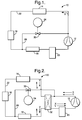
- the air conditioning system 10 in accordance with the present invention is for use in a motor vehicle for heating or cooling the passenger compartment (not shown) of the motor vehicle.
- the air conditioning system 10 comprises the usual components of a compressor 12, an outside heat exchanger 14, an orifice tube or expansion device 16, an inside heat exchanger 18, and an accumulator/dryer 20. These components are connected, as shown in Figure 1, by a main tube 22 for the circulation of refrigerant fluid in the direction X.
- These components of the air conditioning system 10 provide cooling for the passenger compartment in a manner well known to those skilled in the art, and will not be described in greater detail.
- the present invention provides supplemental heating or initial heating for the passenger compartment (for example, when the vehicle is initially started) by simple modifications to the known arrangement.
- the air conditioning system 10 further comprises a bypass tube 28 connected to the main tube 22 between the outside heat exchanger 14 and the compressor 12 and between the orifice tube 16 and the inside heat exchanger 18; and a valve 30 positioned in the bypass tube.
- the operation of the valve 30 is controlled by control means 24.
- the valve 30 has a minimum of two operating positions; an open position for fluid flow through the valve, and a closed position to prevent fluid flow through the valve.
- valve 30 During normal operation of the air conditioning system 10, the valve 30 is its closed position and the air conditioning system operates to cool the passenger compartment.
- the valve 30 When initial or supplemental heating of the passenger compartment is required, the valve 30 is moved to its open position. In this mode, the pressure drop in the bypass tube 28 and in the valve 30 is lower than the pressure drop created in the main tube 22, in the outside heat exchanger 14, and in the orifice tube 16. As a consequence, most of the refrigerant fluid is forced to circulated through the bypass tube 28, inside heat exchanger 18, accumulator/dryer 20 and compressor 12 only. This arrangement is such that the energy contained in the superheated vapour from the compressor 12 can be transferred to the cold ambient air when flowing through the inside heat exchanger 18. Then the vapour passes into the accumulator/dryer 20 (where any liquid refrigerant fluid is retained), before returning to the compressor 12. By this arrangement, initial or supplemental heating of the passenger compartment is achieved.
- the second embodiment of air conditioning system 100 shown in Figure 2 is substantially the same as the first embodiment described above, and like parts have been given the same reference numeral.
- a reversing valve 32 is positioned in the system 100 between the compressor 12 and the outside heat exchanger 14 and between the inside heat exchanger 18 and the accumulator/dryer 20.
- the bypass tube 28 fluidly connects with the main tube 22 between the reversing valve 32 and the compressor 12.
- the valve 30 has an intermediate position between the open position and the closed position which allows restricted fluid flow through the valve.
- valve 30 During normal (cooling) operation of the air conditioning system 100, the valve 30 is its closed position and the reversing valve 32 is set to allow fluid flow in the direction X such that the air conditioning system operates to cool the passenger compartment.
- the valve 30 When initial or supplemental heating of the passenger compartment is required, and the system 100 is in air conditioning (cooling) mode, the valve 30 is moved to its open position. This has the same effect as that described above for the first embodiment of air conditioning system 10 shown in Figure 1.
- the reversing valve 32 When prolonged heating of the passenger compartment is required, the reversing valve 32 is actuated to reverse the flow of refrigerant fluid (in the direction Y) through the inside heat exchanger 18, the orifice tube 16 and the outside heat exchanger 14, during which time, the valve 30 is in its closed position. However, during this cycle, ice can form on the outside heat exchanger 14. In order to remove (melt) the ice, the reversing valve 32 is actuated to switch the air conditioning system 100 to cooling mode (that is, refrigerant fluid flows in direction X). In order to prevent cooling of the passenger compartment (when heating is actually required) during this de-icing phase, the valve 30 is moved to its intermediate position. In this intermediate position of the valve 30, refrigerant fluid is allowed to flow through both the main tube 22 and the bypass tube 28 to de-ice the outside heat exchanger 14 and to substantially prevent or limit cooling of the passenger compartment.
- Alternative reverse flow means rather than the reversing valve 32, may be provided in the air conditioning system in accordance with the present invention, with the valve 30 having the capability of moving to an intermediate position as described above.
- the control means 24 for operating the valve 30 in either of the above embodiments is preferably a contact relay and a manually operable push button which can be located on the dashboard of the motor vehicle.
- the control means 24 may be a temperature sensor which is used to automatically control the operation of the valve 30.
- the relay may be controlled by a microprocessor.
- Either of the above described air conditioning systems 10,100 is simpler and cheaper than the arrangement described in WO-A-95/24323 as the present invention does not require an additional specific expansion device.
- the heating loop is also less sensitive to charge variations in the refrigerant fluid as the accumulator/dryer 20 retains any excess liquid.
- the system of WO-A-95/24323 requires a controllable solenoid valve to prevent refrigerant fluid reaching the outside heat exchanger.
- the operation of the compressor 12 may be controlled by an electronic control module (not shown) which monitors the temperature and/or the pressure of the refrigerant fluid on the high pressure side of the compressor and controls the operation of the compressor to reduce the flow of fluid by the compressor in order to substantially prevent the risk of high torque on the compressor and increased pressure in the fluid.
- an electronic control module not shown which monitors the temperature and/or the pressure of the refrigerant fluid on the high pressure side of the compressor and controls the operation of the compressor to reduce the flow of fluid by the compressor in order to substantially prevent the risk of high torque on the compressor and increased pressure in the fluid.
Landscapes
- Engineering & Computer Science (AREA)
- Physics & Mathematics (AREA)
- Thermal Sciences (AREA)
- Mechanical Engineering (AREA)
- General Engineering & Computer Science (AREA)
- Air-Conditioning For Vehicles (AREA)
Applications Claiming Priority (4)
| Application Number | Priority Date | Filing Date | Title |
|---|---|---|---|
| GBGB9720385.5A GB9720385D0 (en) | 1997-09-26 | 1997-09-26 | Air conditioning system for a motor vehicle |
| GB9720385 | 1997-09-26 | ||
| GB9804259A GB2329702A (en) | 1997-09-26 | 1998-03-02 | Air conditioning system for a motor vehicle |
| GB9804259 | 1998-03-02 |
Publications (2)
| Publication Number | Publication Date |
|---|---|
| EP0904963A2 true EP0904963A2 (fr) | 1999-03-31 |
| EP0904963A3 EP0904963A3 (fr) | 2001-10-31 |
Family
ID=26312318
Family Applications (1)
| Application Number | Title | Priority Date | Filing Date |
|---|---|---|---|
| EP98202900A Withdrawn EP0904963A3 (fr) | 1997-09-26 | 1998-09-01 | Conditionneur d'air pour véhicule automobile |
Country Status (4)
| Country | Link |
|---|---|
| US (1) | US6035658A (fr) |
| EP (1) | EP0904963A3 (fr) |
| JP (1) | JPH11151935A (fr) |
| AU (1) | AU706361B2 (fr) |
Cited By (1)
| Publication number | Priority date | Publication date | Assignee | Title |
|---|---|---|---|---|
| WO2001040004A1 (fr) * | 1999-11-30 | 2001-06-07 | Delphi Technologies, Inc. | Systeme de conditionnement d'air pour vehicule a moteur |
Families Citing this family (4)
| Publication number | Priority date | Publication date | Assignee | Title |
|---|---|---|---|---|
| US8517087B2 (en) * | 2007-02-20 | 2013-08-27 | Bergstrom, Inc. | Combined heating and air conditioning system for vehicles |
| WO2010082325A1 (fr) * | 2009-01-15 | 2010-07-22 | 三菱電機株式会社 | Appareil de conditionnement d'air |
| US11549606B2 (en) * | 2018-11-28 | 2023-01-10 | Mahle International Gmbh | Pilot-pressure-controlled flow valve and fluid system containing same |
| US11597255B2 (en) * | 2020-03-25 | 2023-03-07 | Pony Al Inc. | Systems and methods for cooling vehicle components |
Citations (1)
| Publication number | Priority date | Publication date | Assignee | Title |
|---|---|---|---|---|
| WO1995024323A1 (fr) | 1994-03-10 | 1995-09-14 | Valeo Thermique Habitacle | Dispositif de climatisation de vehicule avec boucle de chauffage |
Family Cites Families (22)
| Publication number | Priority date | Publication date | Assignee | Title |
|---|---|---|---|---|
| GB639313A (en) * | 1947-06-03 | 1950-06-28 | C V Hill & Company Inc | Refrigerating systems |
| US2876629A (en) * | 1954-07-30 | 1959-03-10 | Alco Valve Co | Control for temperature changing device |
| GB1021456A (en) * | 1963-08-21 | 1966-03-02 | Gen Electric | Valve means for a hot gas defrost refrigerating system |
| GB1214650A (en) * | 1967-12-11 | 1970-12-02 | American Air Filter Co | Refrigeration control system |
| CH496931A (de) * | 1968-09-26 | 1970-09-30 | Luwa Ag | Regelbare Kompressor-Kälteanlage |
| GB1454508A (en) * | 1973-04-26 | 1976-11-03 | Shipowners Cargo Res Assoc | Refrigeration control systems |
| US3922875A (en) * | 1974-09-12 | 1975-12-02 | Jr William F Morris | Refrigeration system with auxiliary defrost heat tank |
| US4286435A (en) * | 1978-10-02 | 1981-09-01 | Carrier Corporation | Hot gas defrost system |
| FR2525330A1 (fr) * | 1982-04-14 | 1983-10-21 | Renault Tech Nouvelles | Pompe a chaleur a compression sur l'air entrainee par un moteur thermique et munie d'un dispositif de degivrage |
| GB8328005D0 (en) * | 1983-10-19 | 1983-11-23 | Ferguson Seacabs Ltd | Refrigeration apparatus |
| DE3410861A1 (de) * | 1984-03-23 | 1985-10-03 | KKW Kulmbacher Klimageräte-Werk GmbH, 8650 Kulmbach | Luft- wasser- waermepumpe |
| US4742689A (en) * | 1986-03-18 | 1988-05-10 | Mydax, Inc. | Constant temperature maintaining refrigeration system using proportional flow throttling valve and controlled bypass loop |
| JPH0799297B2 (ja) * | 1986-06-25 | 1995-10-25 | 株式会社日立製作所 | 空気調和機 |
| US4720980A (en) * | 1987-03-04 | 1988-01-26 | Thermo King Corporation | Method of operating a transport refrigeration system |
| US4882908A (en) * | 1987-07-17 | 1989-11-28 | Ranco Incorporated | Demand defrost control method and apparatus |
| US4854130A (en) * | 1987-09-03 | 1989-08-08 | Hoshizaki Electric Co., Ltd. | Refrigerating apparatus |
| US5092134A (en) * | 1989-08-18 | 1992-03-03 | Mitsubishi Denki Kabushiki Kaisha | Heating and cooling air conditioning system with improved defrosting |
| US5070707A (en) * | 1989-10-06 | 1991-12-10 | H. A. Phillips & Co. | Shockless system and hot gas valve for refrigeration and air conditioning |
| JP3237187B2 (ja) * | 1991-06-24 | 2001-12-10 | 株式会社デンソー | 空調装置 |
| JP3463303B2 (ja) * | 1991-12-27 | 2003-11-05 | 日産自動車株式会社 | 車両用ヒートポンプ式冷暖房装置 |
| JP2936936B2 (ja) * | 1993-01-29 | 1999-08-23 | 日産自動車株式会社 | 車両用冷暖房装置 |
| JPH08327169A (ja) * | 1994-08-31 | 1996-12-13 | Nippondenso Co Ltd | 冷凍装置 |
-
1998
- 1998-09-01 EP EP98202900A patent/EP0904963A3/fr not_active Withdrawn
- 1998-09-02 AU AU83048/98A patent/AU706361B2/en not_active Ceased
- 1998-09-11 US US09/151,529 patent/US6035658A/en not_active Expired - Fee Related
- 1998-09-25 JP JP10271531A patent/JPH11151935A/ja active Pending
Patent Citations (1)
| Publication number | Priority date | Publication date | Assignee | Title |
|---|---|---|---|---|
| WO1995024323A1 (fr) | 1994-03-10 | 1995-09-14 | Valeo Thermique Habitacle | Dispositif de climatisation de vehicule avec boucle de chauffage |
Cited By (1)
| Publication number | Priority date | Publication date | Assignee | Title |
|---|---|---|---|---|
| WO2001040004A1 (fr) * | 1999-11-30 | 2001-06-07 | Delphi Technologies, Inc. | Systeme de conditionnement d'air pour vehicule a moteur |
Also Published As
| Publication number | Publication date |
|---|---|
| US6035658A (en) | 2000-03-14 |
| AU8304898A (en) | 1999-04-15 |
| JPH11151935A (ja) | 1999-06-08 |
| EP0904963A3 (fr) | 2001-10-31 |
| AU706361B2 (en) | 1999-06-17 |
Similar Documents
| Publication | Publication Date | Title |
|---|---|---|
| US5904052A (en) | Brine type air conditioning apparatus | |
| EP0913282B1 (fr) | Système de conditionnement d'air utilisant une pompe à chaleur pour véhicule automobile | |
| US7003975B2 (en) | Heating/cooling circuit for an air-conditioning system of a motor vehicle, air-conditioning system and a method for controlling the same | |
| JP3781147B2 (ja) | ヒートポンプ式自動車用空気調和装置 | |
| US6230505B1 (en) | Heat pump type air conditioning system for automotive vehicle | |
| US5560217A (en) | Air conditioning system of heat pump type | |
| JP3794121B2 (ja) | 車両用空調装置 | |
| EP0681933B1 (fr) | Système de conditionnement d'air utilisant une pompe à chaleur | |
| EP1295739B1 (fr) | Installation combinée de chauffage et de réfrigération | |
| EP0678409A1 (fr) | Appareil de conditionnement d'air | |
| JP3253501B2 (ja) | 電気自動車用冷暖房装置 | |
| US6035658A (en) | Air conditioning system for a motor vehicle | |
| JPH1142933A (ja) | 空気調和装置 | |
| JP5823485B2 (ja) | 2つの膨張部材の間に直接配置された熱交換器を含む空調ループ | |
| JP3993760B2 (ja) | 車両用空調装置 | |
| JP3977629B2 (ja) | 車両用空調装置 | |
| JP4073653B2 (ja) | 車両用空調装置 | |
| KR20230075230A (ko) | 차량용 공조시스템의 제어방법 | |
| GB2329702A (en) | Air conditioning system for a motor vehicle | |
| JPH0899526A (ja) | 車両用冷暖房装置 | |
| JPH1044758A (ja) | ヒートポンプ式自動車用空気調和装置 | |
| JP3684673B2 (ja) | バス用空調装置 | |
| KR100269668B1 (ko) | 자동차용 열 펌프형 공조 시스템 | |
| JPH1058965A (ja) | ヒートポンプ式自動車用空気調和装置 | |
| JPH11170857A (ja) | ヒートポンプ式自動車用空気調和装置 |
Legal Events
| Date | Code | Title | Description |
|---|---|---|---|
| PUAI | Public reference made under article 153(3) epc to a published international application that has entered the european phase |
Free format text: ORIGINAL CODE: 0009012 |
|
| AK | Designated contracting states |
Kind code of ref document: A2 Designated state(s): AT BE CH CY DE DK ES FI FR GB GR IE IT LI LU MC NL PT SE |
|
| AX | Request for extension of the european patent |
Free format text: AL;LT;LV;MK;RO;SI |
|
| RAP1 | Party data changed (applicant data changed or rights of an application transferred) |
Owner name: DELPHI TECHNOLOGIES, INC. |
|
| PUAL | Search report despatched |
Free format text: ORIGINAL CODE: 0009013 |
|
| AK | Designated contracting states |
Kind code of ref document: A3 Designated state(s): AT BE CH CY DE DK ES FI FR GB GR IE IT LI LU MC NL PT SE |
|
| AX | Request for extension of the european patent |
Free format text: AL;LT;LV;MK;RO;SI |
|
| AKX | Designation fees paid | ||
| REG | Reference to a national code |
Ref country code: DE Ref legal event code: 8566 |
|
| STAA | Information on the status of an ep patent application or granted ep patent |
Free format text: STATUS: THE APPLICATION IS DEEMED TO BE WITHDRAWN |
|
| 18D | Application deemed to be withdrawn |
Effective date: 20020403 |