EP0904947A1 - Farbbandkassette zur Reduzierung der Abmessungen eines Druckers und Verfahren zu ihrer Bereitstellung - Google Patents
Farbbandkassette zur Reduzierung der Abmessungen eines Druckers und Verfahren zu ihrer Bereitstellung Download PDFInfo
- Publication number
- EP0904947A1 EP0904947A1 EP98203067A EP98203067A EP0904947A1 EP 0904947 A1 EP0904947 A1 EP 0904947A1 EP 98203067 A EP98203067 A EP 98203067A EP 98203067 A EP98203067 A EP 98203067A EP 0904947 A1 EP0904947 A1 EP 0904947A1
- Authority
- EP
- European Patent Office
- Prior art keywords
- spool
- take
- printer
- cartridge
- print head
- Prior art date
- Legal status (The legal status is an assumption and is not a legal conclusion. Google has not performed a legal analysis and makes no representation as to the accuracy of the status listed.)
- Withdrawn
Links
- 238000000034 method Methods 0.000 title claims abstract description 8
- 238000003780 insertion Methods 0.000 abstract description 4
- 230000037431 insertion Effects 0.000 abstract description 4
- 238000012546 transfer Methods 0.000 description 4
- 230000003213 activating effect Effects 0.000 description 2
- 238000013467 fragmentation Methods 0.000 description 2
- 238000006062 fragmentation reaction Methods 0.000 description 2
- 238000010438 heat treatment Methods 0.000 description 2
- VWLWUCKZXTYFGA-UHFFFAOYSA-N 3,5-dimethyl-4,6-diphenyl-1,3,5-thiadiazinane-2-thione Chemical compound CN1C(C=2C=CC=CC=2)SC(=S)N(C)C1C1=CC=CC=C1 VWLWUCKZXTYFGA-UHFFFAOYSA-N 0.000 description 1
- 238000004891 communication Methods 0.000 description 1
- 230000002708 enhancing effect Effects 0.000 description 1
- 238000012986 modification Methods 0.000 description 1
- 230000004048 modification Effects 0.000 description 1
Images


Classifications
-
- B—PERFORMING OPERATIONS; TRANSPORTING
- B41—PRINTING; LINING MACHINES; TYPEWRITERS; STAMPS
- B41J—TYPEWRITERS; SELECTIVE PRINTING MECHANISMS, i.e. MECHANISMS PRINTING OTHERWISE THAN FROM A FORME; CORRECTION OF TYPOGRAPHICAL ERRORS
- B41J31/00—Ink ribbons; Renovating or testing ink ribbons
- B41J31/10—Ink ribbons having arrangements to facilitate threading through a machine
-
- B—PERFORMING OPERATIONS; TRANSPORTING
- B41—PRINTING; LINING MACHINES; TYPEWRITERS; STAMPS
- B41J—TYPEWRITERS; SELECTIVE PRINTING MECHANISMS, i.e. MECHANISMS PRINTING OTHERWISE THAN FROM A FORME; CORRECTION OF TYPOGRAPHICAL ERRORS
- B41J17/00—Mechanisms for manipulating page-width impression-transfer material, e.g. carbon paper
- B41J17/32—Detachable carriers or holders for impression-transfer material mechanism
Definitions
- This invention generally relates to printer apparatus and methods and more particularly relates to a printer dye cartridge adapted to reduce an exterior envelope of a printer and method of providing same.
- a typical thermal printer has an enclosure for enclosing the components of the printer.
- Receiver medium is held in a supply tray at least partially insertable into the enclosure for supplying the receiver medium to a print head housed in the enclosure.
- a "picker" mechanism engages the receiver medium held in the supply tray and feeds the receiver medium to the print head.
- the receiver medium fed to the print head is brought into contact with a dye donor web carried by a dye donor cassette also insertable into the enclosure, the cassette capable of being disposed near the print head.
- the print head heat activates the dye donor web to transfer the dye to the receiver medium in order to print an output image on the receiver medium.
- the enclosure and the supply tray define an exterior envelope of the printer.
- the dye donor cassette is usually inserted into the printer by opening a top panel of the printer and lowering the dye donor cassette into position in the printer.
- printers are often placed in a confined space with limited head room.
- such printers are often placed on shelves, wherein the floor of an adjacent upper shelf forms a relatively low ceiling above the top panel of the printer.
- this ceiling creates an interference or obstruction to opening the top panel.
- This makes loading the dye donor cassette difficult and time-consuming because the printer first must be removed from the shelf in order to open the top panel before loading the dye donor cassette into the printer. Therefore, it would be desirable to provide a dye donor cassette and associated printer obviating the need to open the top panel in order to load the dye donor cassette.
- an object of the present invention is to provide a suitable cartridge that obviates the need to load the dye donor cartridge by opening the top panel of the printer.
- the invention resides in for use in a thermal resistive printer, a dye cartridge, comprising: (a) a case having an enlarged portion defining a chamber therein and having a plurality of spaced-apart parallel tines integrally connected to the enlarged portion; (b) a first spool disposed in the chamber; and (c) a second spool interposed between the tines, said second spool having a non-round transverse cross section.
- a dye donor cartridge is insertable through an aperture in a printer housing to a position adjacent the print head.
- the cartridge has an elongate neck portion defining a longitudinal axis therealong and is sized to be received through the clearance for interference-free insertion of the cartridge to a position between the print head and the platen.
- the cartridge includes a supply spool at one end of the cartridge for engaging a first end portion of a dye donor ribbon carried by the cartridge and which extends through the neck portion.
- a take-up spool is disposed at another end of the cartridge in the neck portion for engaging a second end portion of the dye donor ribbon.
- the take-up spool itself has an elliptically-shaped transverse cross section defining a major axis and is capable of being oriented such that the major axis of the take-up spool is parallel with the longitudinal axis of the neck portion.
- the elliptically-shaped take-up spool which is disposed in the neck portion, allows the neck portion, including its take-up spool, to be inserted through the clearance so that the neck portion and the take-up spool do not create an interference with the print head.
- a biasing mechanism may also be provided for biasing the take-up spool in order to bring the major axis of the take-up spool parallel with the longitudinal axis of the neck portion as the neck portion is inserted through the clearance.
- the cartridge can be loaded through the aperture in the front sidewall rather than by opening a top panel of the printer, so that the exterior envelope of the printer is reduced. This allows the printer to reside in a confined space with limited headroom.
- a feature of the present invention is the provision of a cartridge having an elliptically-shaped take-up spool disposed in an elongate neck portion that is sized to be received through a clearance defined between a print head and a platen for interference-free insertion of the cartridge.
- An advantage of the present invention is that the printer has a reduced exterior envelope resulting from the cartridge being loaded through the aperture in the front sidewall rather than by means of opening a top panel of the printer in order that the printer may reside in a confined space with limited headroom.
- the present invention is directed in particular to elements forming part of, or cooperating more directly with, apparatus in accordance with the present invention. It is to be understood that elements not specifically shown or described may take various forms well known to those skilled in the art.
- printer 10 such as a thermal resistive printer, generally referred to as 10, for printing an image on a dye receiver 20, which receiver 20 may be a roll or a plurality of cut sheets of coated paper or transparency fed from a receiver medium supply tray 30.
- printer 10 has a reduced exterior envelope so that printer 10 may be placed in a confined space 40, such as defined by a shelf structure 50 bounded by a floor 60, a rear wall 70 and a relatively low ceiling 80 overhanging printer 10.
- printer 10 comprises a housing 90 defining an exterior envelope thereabout and an interior 100 therein.
- Housing 90 includes a top wall 110 and a front sidewall 120, front sidewall 120 having an opening 130 sized to receive supply tray 30 which is at least partially insertable through opening 130.
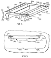
- an aperture 140 for receiving the subject matter of the present invention, which is a dye-carrying dye donor supply cartridge 150 having an outer case 155.
- cartridge 150 carries a thermally activatable dye donor ribbon 160.
- a thermal resistive print head 170 for thermally activating dye donor ribbon 160 in order to transfer dye therein onto each of sheets 20.
- thermal print head 170 is formed of a plurality of individual resistive heating elements (not shown) such that when a particular heating element is energized, its heat causes dye from dye donor ribbon 160 to transfer to sheet 20 for forming an image thereon.
- Printer 10 may also include an output tray assembly 180 for receiving sheets 20 after the image is formed on each sheet 20.
- a picker roller 190 is disposed in housing 90 for separately urging each sheet 20 into a gap or nip area 200 (see Fig. 2) defined between print head 170 and a platen 210, which platen 210 is also disposed in housing 90.
- printer 10 further comprises a movable arm 220 having a first end portion 222 connected to print head 170 and a second end portion 225 connected to a joint 230 interconnecting arm 220 to a stationary support member 240.
- Arm 220 is capable of pivoting about joint 230 through a predetermined angle " ⁇ " of approximately 10 degrees entirely within housing 90.
- print head 170 moves from a first position spaced-apart from platen 210 to second position adjacent platen 210.
- print head 170 defines a clearance "d" between print head 170 and platen 210.
- this clearance "d" is substantially reduced when print head 170 moves to the second position thereof.
- cartridge 150 which is insertable through aperture 140 of front sidewall 120, includes an enlarged end portion 250 defining a chamber 260 therein in communication with an opening 270, for reasons disclosed hereinbelow.
- chamber 260 Disposed in chamber 260 is a cylindrical supply spool 280 surrounding a first axle 290 centered longitudinally through supply spool 280, which first axle 290 in turn is connected to a first motor (not shown) for rotating axle 290.
- supply spool 280 rotates as axle 290 rotates.
- Cartridge 150 further comprises an elongate neck portion 300 formed by a pair of spaced-apart parallel tines 310a and 310b, each tine 310a/310b having a first end portion 315a and 315b, respectively, integrally attached to enlarged portion 250.
- cartridge 150 defines a longitudinal axis 317 centered between tines 310a/310b.
- an elongate guard shield 320 may interconnect second end portions 325a and 325b of tines 310a and 310b, respectively, for reasons provided hereinbelow.
- an elongate dye donor ribbon guide pin 330 is disposed in neck portion 300 between enlarged end portion 250 and guard shield 320.
- Guide pin 330 extends between tines 310a/310b, for reasons disclosed more fully hereinbelow.
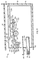
- a take-up spool 340 interposed between tines 310a/b in neck portion 300 is a take-up spool 340 surrounding a second axle 350 which in turn is connected to a second motor (not shown) for rotating second axle 350.
- take-up spool 340 rotates as second axle 350 rotates.
- the first motor causes supply spool 280 to rotate in a clockwise direction and the second motor causes take-up spool 340 to rotate in a counter-clockwise direction (when cartridge 150 is viewed from the side of cartridge containing tine 310b).
- guard shield 320 protects take-up spool 340 from possible damage as cartridge 150 is inserted into housing 90.
- second axle 350 terminates in a generally elliptically-shaped hub 355 integrally attached to second axle 350.
- Hub 355 is preferably disposed on the outboard side of tine 310a. However, hub 355 may be disposed on the outboard side of tine 310b, if desired.
- dye donor cartridge 150 carries thermally activatable dye donor ribbon 160. Therefore, it may be appreciated that a first end portion of dye donor ribbon 160 is necessarily attached to supply spool 280 and a second end portion of dye donor ribbon 160 is necessarily attached to take-up spool 340.
- the dye donor ribbon 160 is initially substantially wound about supply spool 280 and is subsequently unwound therefrom onto take-up spool 340 as the first and second motors operate.
- take-up spool 340 has a non-round generally "flattened” or elliptically-shaped transverse cross section defining a major axis 360. It is important that take-up spool 340 have an elliptically-shaped transverse cross section. This is important for the reasons provided immediately hereinbelow. That is, the elliptically-shaped transverse cross section provides take-up spool 340 with a minor axis that is substantially shorter than its major axis 360 (when take-up spool 340 is viewed in transverse cross section).
- take-up spool 340 is sized such that when major axis 360 is brought parallel to longitudinal axis 317 take-up spool 340 will assume a position within neck portion 300 such that no portion of take-up spool 340 extends beyond the edges of neck portion 300. This is so because angle " ⁇ " need not be increased to accommodate passage of both take-up spool 340 as well as neck portion 300. This in turn minimizes the previously mentioned angle " ⁇ " when neck portion 300 is inserted through clearance "d” to be positioned in nip 200. Again, this is true because no portion of take-up spool 340 extends beyond the edges of neck portion 300 when major axis 360 is parallel to longitudinal axis 317.
- minimizing angle " ⁇ " minimizes the clearance distance "d" through which print head 170 must be lifted in order to provide interference-free clearance for passage of neck portion 300.
- Minimizing the clearance distance "d” through which print head 170 must be lifted allows print head 170 to be lifted entirely within housing 90, thereby avoiding the need to open top wall 110 of housing 90.
- avoiding the need to open top wall 110 of housing 90 results from being able to load cartridge 150 through aperture 140 of front sidewall 120 (rather than loading cartridge 150 through top wall 110) in the manner described.
- This feature of the present invention allows printer 10 to be disposed in confined space 40 with limited headroom.
- print head 170 is moved, by any suitable means, to its second position and printing may commence.
- take-up spool 340 rotates in order to "take-up" dye donor ribbon 160 being unwound from supply spool 280.
- Dye donor ribbon 160 slidably engages previously mentioned guide pin 330 in order to provide proper tensioning of ribbon 160 as take-up spool 340 "takes-up" ribbon 160.
- biasing mechanism 370 may be provided for biasing take-up spool 340 so that major axis 360 thereof is oriented parallel with respect to longitudinal axis 317 when take-up spool 340 is not rotating (for example, when neck portion is being inserted into clearance "d" prior to printing).
- biasing mechanism 370 comprises a tab member 380 connected either to tine 310a or 310b, as the case may be, by means of a coiled spring 390 which biases tab member 380 in the direction shown by a curved arrow 400.
- tab member 380 As tab member 380 is biased in the direction of arrow 400, it exerts a biasing force against the previously mentioned hub 355 so that hub 355 obtains a preferred direction (that is, major axis 360 parallel to longitudinal axis 317) as neck portion 300 is being received into clearance "d". In this manner, take-up spool 340 will not interfere with print head 170, as previously mentioned.
- printer 10 has a reduced exterior envelope so that it can be disposed in confined space 40 which has limited headroom. This is so because dye donor cartridge 150 can be loaded, interference-free, into housing 90 through aperture 140 in front sidewall 120 rather than by opening a top panel of printer 10.
- supply spool 280 may also be provided with an elliptical transverse cross section similar to the elliptical transverse cross section of take-up spool 340.
- the advantage of providing both take-up spool 340 and supply spool 280 with an elliptical transverse cross section is that cartridge 150 will then assume a svelte almost entirely elongate profile for enhancing the aesthetic appearance thereof and for conserving space when a plurality of cartridges 150 are stacked in a storage area.
- a dye cartridge adapted to reduce an exterior envelope of a printer and method of providing same.
Landscapes
- Impression-Transfer Materials And Handling Thereof (AREA)
Applications Claiming Priority (2)
| Application Number | Priority Date | Filing Date | Title |
|---|---|---|---|
| US938868 | 1992-09-02 | ||
| US08/938,868 US5909973A (en) | 1997-09-26 | 1997-09-26 | Ink ribbon cartridge with an elliptical take-up spool |
Publications (1)
| Publication Number | Publication Date |
|---|---|
| EP0904947A1 true EP0904947A1 (de) | 1999-03-31 |
Family
ID=25472101
Family Applications (1)
| Application Number | Title | Priority Date | Filing Date |
|---|---|---|---|
| EP98203067A Withdrawn EP0904947A1 (de) | 1997-09-26 | 1998-09-14 | Farbbandkassette zur Reduzierung der Abmessungen eines Druckers und Verfahren zu ihrer Bereitstellung |
Country Status (3)
| Country | Link |
|---|---|
| US (1) | US5909973A (de) |
| EP (1) | EP0904947A1 (de) |
| JP (1) | JPH11157190A (de) |
Cited By (1)
| Publication number | Priority date | Publication date | Assignee | Title |
|---|---|---|---|---|
| WO2007119387A1 (en) * | 2006-03-15 | 2007-10-25 | Canon Kabushiki Kaisha | Cassette and printer |
Families Citing this family (1)
| Publication number | Priority date | Publication date | Assignee | Title |
|---|---|---|---|---|
| EP0891871B1 (de) * | 1997-07-15 | 2004-03-03 | Alps Electric Co., Ltd. | Druckkassette |
Citations (3)
| Publication number | Priority date | Publication date | Assignee | Title |
|---|---|---|---|---|
| DE3939886A1 (de) * | 1989-02-03 | 1990-08-09 | Siemens Ag | Farbbandkassette und ihre verwendung in einer bildaufzeichnungsvorrichtung |
| EP0472471A2 (de) * | 1990-08-21 | 1992-02-26 | Sony Corporation | Kassette für mittels Übertragung arbeitenden Aufzeichnungsträger und Aufzeichnungsvorrichtung |
| US5277502A (en) | 1990-02-24 | 1994-01-11 | Goldstar Co., Ltd. | Device for loading ink film and printing papers in color video printer |
Family Cites Families (4)
| Publication number | Priority date | Publication date | Assignee | Title |
|---|---|---|---|---|
| JPS59177774A (ja) * | 1983-03-28 | 1984-10-08 | Asahi Chem Ind Co Ltd | カセツト |
| DE315488T1 (de) * | 1987-11-06 | 1989-12-07 | Victor Company Of Japan, Ltd., Yokohama, Kanagawa | Anordnung zur thermischen aufzeichnung. |
| JP2514547Y2 (ja) * | 1988-02-26 | 1996-10-23 | ミノルタ株式会社 | 熱転写記録装置 |
| US5597249A (en) * | 1993-10-15 | 1997-01-28 | Monarch Marking Systems, Inc. | Ink ribbon cartridge |
-
1997
- 1997-09-26 US US08/938,868 patent/US5909973A/en not_active Expired - Fee Related
-
1998
- 1998-09-14 EP EP98203067A patent/EP0904947A1/de not_active Withdrawn
- 1998-09-28 JP JP10273632A patent/JPH11157190A/ja active Pending
Patent Citations (3)
| Publication number | Priority date | Publication date | Assignee | Title |
|---|---|---|---|---|
| DE3939886A1 (de) * | 1989-02-03 | 1990-08-09 | Siemens Ag | Farbbandkassette und ihre verwendung in einer bildaufzeichnungsvorrichtung |
| US5277502A (en) | 1990-02-24 | 1994-01-11 | Goldstar Co., Ltd. | Device for loading ink film and printing papers in color video printer |
| EP0472471A2 (de) * | 1990-08-21 | 1992-02-26 | Sony Corporation | Kassette für mittels Übertragung arbeitenden Aufzeichnungsträger und Aufzeichnungsvorrichtung |
Cited By (4)
| Publication number | Priority date | Publication date | Assignee | Title |
|---|---|---|---|---|
| WO2007119387A1 (en) * | 2006-03-15 | 2007-10-25 | Canon Kabushiki Kaisha | Cassette and printer |
| RU2367578C1 (ru) * | 2006-03-15 | 2009-09-20 | Кэнон Кабусики Кайся | Кассета и принтер |
| CN100584634C (zh) * | 2006-03-15 | 2010-01-27 | 佳能株式会社 | 盒以及打印机 |
| US8317419B2 (en) | 2006-03-15 | 2012-11-27 | Canon Kabushiki Kaisha | Cassette for printer with thermal head contact portion |
Also Published As
| Publication number | Publication date |
|---|---|
| JPH11157190A (ja) | 1999-06-15 |
| US5909973A (en) | 1999-06-08 |
Similar Documents
| Publication | Publication Date | Title |
|---|---|---|
| EP0790134B1 (de) | Bandkassette | |
| US6069642A (en) | Cassette for holding ink ribbon and print paper therein and printer incorporating the cassette therein | |
| CN100513187C (zh) | 带式打印机 | |
| JP5725750B2 (ja) | 給紙装置 | |
| EP1798050B1 (de) | Papierrollenzuführmechanismus und bilderzeugende Vorrichtung | |
| EP1120268A2 (de) | Farbbandkassette für Thermotransferdrucker | |
| US6753894B2 (en) | Image recording apparatus, thermal transfer ink ribbon and thermal transfer ink ribbon cassette used in this image recording apparatus | |
| JP2010253846A (ja) | インクリボンカートリッジ | |
| US5909973A (en) | Ink ribbon cartridge with an elliptical take-up spool | |
| US5927873A (en) | Printer defining a reduced exterior envelope thereof and method of providing same | |
| JP5407711B2 (ja) | ラベル作成装置 | |
| RU2370374C1 (ru) | Кассета для печатающего устройства | |
| US5087926A (en) | Dual toggle mechanism for pressing a thermal printing head against a platen roll in a printer for use with an insertable cassette | |
| EP0630756B1 (de) | Austauschbare Bandeinheit | |
| US5924805A (en) | Printer defining a reduced exterior envelope thereof and method of providing same | |
| US5885014A (en) | Printer defining a reduced exterior envelope thereof and method of providing same | |
| JPH10291350A (ja) | 給紙カートリッジ | |
| US5908250A (en) | Dye cartridge system adapted to reduce an exterior envelope of a printer and method of providing same | |
| JP2001191597A (ja) | プリンタ | |
| JP5263685B2 (ja) | ラベル作成装置 | |
| US5835118A (en) | Dye cartridge system and method adapted to tension a dye ribbon associated therewith | |
| JP2007160801A (ja) | ロール紙給紙機構、ロール紙給紙カセット、及び画像形成装置 | |
| US20040263606A1 (en) | Roll paper feeding device and photo printer | |
| US20240034077A1 (en) | Printing apparatus | |
| RU2369486C1 (ru) | Кассета для печатающего устройства |
Legal Events
| Date | Code | Title | Description |
|---|---|---|---|
| PUAI | Public reference made under article 153(3) epc to a published international application that has entered the european phase |
Free format text: ORIGINAL CODE: 0009012 |
|
| AK | Designated contracting states |
Kind code of ref document: A1 Designated state(s): DE FR GB |
|
| AX | Request for extension of the european patent |
Free format text: AL;LT;LV;MK;RO;SI |
|
| 17P | Request for examination filed |
Effective date: 19990910 |
|
| AKX | Designation fees paid |
Free format text: DE FR GB |
|
| 17Q | First examination report despatched |
Effective date: 20000710 |
|
| STAA | Information on the status of an ep patent application or granted ep patent |
Free format text: STATUS: THE APPLICATION IS DEEMED TO BE WITHDRAWN |
|
| 18D | Application deemed to be withdrawn |
Effective date: 20001121 |