EP0904903A2 - Dispositif pour dégauchir de pièces de bois - Google Patents
Dispositif pour dégauchir de pièces de bois Download PDFInfo
- Publication number
- EP0904903A2 EP0904903A2 EP98100133A EP98100133A EP0904903A2 EP 0904903 A2 EP0904903 A2 EP 0904903A2 EP 98100133 A EP98100133 A EP 98100133A EP 98100133 A EP98100133 A EP 98100133A EP 0904903 A2 EP0904903 A2 EP 0904903A2
- Authority
- EP
- European Patent Office
- Prior art keywords
- disk
- angle
- cutting
- guide plate
- rotor
- Prior art date
- Legal status (The legal status is an assumption and is not a legal conclusion. Google has not performed a legal analysis and makes no representation as to the accuracy of the status listed.)
- Granted
Links
Images



Classifications
-
- B—PERFORMING OPERATIONS; TRANSPORTING
- B27—WORKING OR PRESERVING WOOD OR SIMILAR MATERIAL; NAILING OR STAPLING MACHINES IN GENERAL
- B27C—PLANING, DRILLING, MILLING, TURNING OR UNIVERSAL MACHINES FOR WOOD OR SIMILAR MATERIAL
- B27C1/00—Machines for producing flat surfaces, e.g. by rotary cutters; Equipment therefor
- B27C1/04—Thicknessing machines
-
- B—PERFORMING OPERATIONS; TRANSPORTING
- B27—WORKING OR PRESERVING WOOD OR SIMILAR MATERIAL; NAILING OR STAPLING MACHINES IN GENERAL
- B27C—PLANING, DRILLING, MILLING, TURNING OR UNIVERSAL MACHINES FOR WOOD OR SIMILAR MATERIAL
- B27C1/00—Machines for producing flat surfaces, e.g. by rotary cutters; Equipment therefor
- B27C1/005—Machines for producing flat surfaces, e.g. by rotary cutters; Equipment therefor with tools having a rotational vector which is perpendicular to the working surface
Definitions
- the invention relates to the device for surface processing of wooden workpieces or, more precisely, the machine for woodworking with a rotary tool, for surface processing and thickness processing of wooden workpieces, or for smoothing the surface and reducing the thickness, with characteristic attachment of the cutting tool.
- the invention is classified in B 27 / C 1/00 and additionally in B 27G 13/10.
- the technical problem solved by the invention is one Construction of the machine, which is a high quality fine Surface processing of wooden workpieces on the whole Surface, even when leaving the Machining area, and which continues to be easy to insert and a precise setting of the cutting units in the ring gear of the Machining head, equipped with direct drive and Braking mechanism, enables.
- the machining head inserted between two plates for the passage of workpieces, is attached to the rotary shaft, in which the track plate is inserted, which is fixedly attached to one or both side guide rails.
- the longitudinal axis of the rotating shaft is orthogonally attached to the input and output slide plates and is orthogonal to the circular insert, the guide surface of which is in the same plane as the slide surface of the output slide plate.
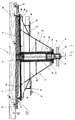
- the machine for surface processing of wooden workpieces consists of the machining head 1 with the end disk 3 and ring gear 4, Rotor 2, guide plate 5, fixed axis 8, brake disc 10 with mechanical brake 11 and input plate 15 and output plate 16, which for the first embodiment of FIG. 1 and for that second embodiment of FIG. 2 applies, in which the Machining head 1 in the opening between the vertically movable Plate 15 and the fixed output plate 16 is attached.
- the Machining head 1 composed of the upright attached Hollow rotor 2, which has fastening elements 17 at one end attached face disk 3 with ring gear 4 and not marked Hole in the middle, at the other end is with the Fasteners 12, the brake disc 10 with mechanical Brake 11 attached.
- the end disk 3 is not by that marked hole in the middle in the specially designed warehouse on the outer edge of the hollow rotor 2 placed so that they with the Gear ring 4 or with the cutting units 19 den Plates 15 and 16 face.
- On the side of the cutting units 19 is the circular in the end face of the circular disc 3 Well 20 executed.
- the fixed axis 8 is in or through the rotor 2 used that they are on the side of the end disk 3 with the hub 52 rests on its end face via the intermediate sealing ring 53, on the side of the brake disc 10 but somewhat above the rotor 2 extends.
- the spacer 6 is wedge-shaped in cross section and not in that marked recessed bearing on the back of the guide plate 5 used.
- the fixed or resting structure of the first Preferred embodiment from FIG. 1 form the fixed axis 8 the guide plate 5 and spacer 6, attached to the hub 52 at one end and with the clamping bush 13 in the frame 14 on other end.
- the rotating structure of the exemplary embodiment from FIG. 1 form the rotor 2 with the ring disk 3 and ring gear 4 in one and with the brake disc 10 at the other end.
- the rotating Structure is created by what is not described and not shown Drive unit driven, and that over the intermediate Driving belt 18, attached to the outer edge of the rotor 2, the is also the pulley of this structure.
- the processing head 1 of the embodiment of the machine for Surface processing of wooden workpieces according to the invention Fig.1 is in the opening between the input plate 15 and Output plate 16 attached so that the outer edges C of Cutting units 19 in the opening between the edge of the Input plate 15 and the edge of the guide plate 5 are in the same level or slightly above the surfaces D of the guide plate 5 and F of the output plate 16, the areas D and F being constant in are on the same level.
- the outer edges E of the cutting units 19, in the opening between the edge of the guide plate 5 and the Edge of the output plate 16 and the surface G of the input plate 15, are constantly slightly below the plane of the surfaces D and F.
- the processing head 1 is in this Embodiment attached between the plates 15 and 16, that the entire longitudinal central axis of the rotor 2, the end disk 3 and the fixed axis 8 by the angle ⁇ from the vertical of the bill is offset on the end faces D, F and G, in the direction the input plate 15.
- This is also the longitudinal central axis the end disk 3 by the angle ⁇ from the horizontal surface D the guide plate 5 offset, which also for the angular displacement the edge E with respect to the edge C of the cutting units 19 applies, and in the position shown in FIG. 1.
- the method of surface machining of workpieces 51 or the process of processing them to any thickness begins with the thickness adjustment of the material decrease, that with vertically movable input plate 15 is set and the Height difference between the edge C on the cutting units 19 and the surface G of the input plate 15.
- the Drive unit and the drive belt 18 By the Drive unit and the drive belt 18, the rotor 2nd rotated, together with the end disk 3.
- the workpiece 51 moves on the surface G of the input plate 15 to the edge C. of the cutting units 19, with the transition over the Cutting units 19 the material removal on the abutting surface of the workpiece 51. Doing so the workpiece 51 of not shown and not described Feeding device down or onto surface D the guide plate 5 pressed.
- the end plate of the hub 52 of the fixed axis 8 can also be designed at the angle, the design of the intermediate spacer 6 being omitted.
- the rotor 2, the end disk 3, the ring gear 4, the guide plate 5, the fixed axis 8 and their fastening in the machine frame 14 and the brake disk 10 with the brake 11 can also be designed differently.
- the ring gear 4 is shown, carried out in the entire circumference of the end disk 3 with such a circular recess 20 in one piece and which has cutting units 19 which are interchangeably inserted or attached over the entire circumference.
- the type of insertion and the principle of setting the cutting units 19 in the ring gear 4 of the end disk 3 is shown in FIG. 5.
- the individual cutting unit 19 consists of the cylindrical support body 35, with chamfered smooth / flat surface 45 and bearing 46, from the cutting disc 36, the wedge 37 with chamfered oblique surface 47 and with the central hole 48 with an internal thread, furthermore it consists of the compression spring 38, the binding or fastening element 39 and fastening element 40.
- the individual cutting unit 19 is in the ring gear 4 End disk 3 used so that you are in the vertical blind Hole 41 first places the compression spring 38 in the horizontal blind Hole 42 uses the wedge 37 with the fastener 40. Then you put on the compression spring 38, the support body 35, with the Cutting disc 36, fastened with the fastener 39. The Support body 35 is inserted into the hole 41 so that its straight Surface 45 lies in the direction of the center of the end disk 3 and on or rests on the surface 47 of the wedge 37.
- Support body 35 with the cutting disc 36 is set to a certain Height adjusted with the help of the compression spring 38 and fixed attached so that by tightening the fastener 40 the inclined surface 47 on the wedge 37 to the smooth surface 45 on the Tightens the support body 35 and fix it in this way in the ring gear 4th solidified.
- the radial depressions 49 allow one larger stop of the cutting units 19 in the ring gear 4, the adjacent radial depressions 50, however, allow undisturbed Separation of the wood chips.
- the cutting discs 36 are in the bearing 46 on the support body 35 used and fastened with the binding element 39 so that in the Front view its upper cutting edge is below the angle ⁇ , or the cutting edge for this free angle from the imaginary horizontal axis is shown in Fig. 6, wherein the cutting discs 36 any regular and irregular can have geometric shapes.
- Fig. 7 the support body 35 with attached cutting disc 36 in shown the side view. It can be seen from this that the bearing 46 is carried out on the support body 35 at the positive angle ⁇ , and the cutting disc 36 is also attached at this angle, the cutting disc 36 and the straight surface 45 with the larger end face in the direction of turning the end disk 3 or their ring gear 4 are oriented.
- the positive Angle ⁇ of the inclination of the cutting disc 36 from the The longitudinal central axis of the support body 35 represents the angle of the chip, the individual cutting disc 36 of the respective cutting unit 19 on the ring gear 4 of the end disk 3 on the side of Surface processing of the workpiece 51 cuts off.
- the machining head 1 is composed of the attached rotor 2, in a welded design and V shape, which on the wider end of the hollow truncated cone 32 has the fixedly attached end disk 3 with ring gear 4 and with the upright one , Has hollow tube 28 open on both sides in the middle, but at its other end the plate 53 is fixed.
- the hollow tube 28 is passed through the rotor 2, the end disk 3 and the plate 53 and is preferably the same length as the structure described.
- the hollow truncated cone 32 and the end disk 3 are surrounded in their entire circumference by the fixed hollow truncated cone 31, the rotor 2 is additionally reinforced with the inner ring 29, the outer rib 30, the outer ring 33 and the intermediate ring 34.
- the brake disk 10 with the mechanical brake 11 and the pulley 25 are also fixedly attached to the intermediate ring 34.
- the end disk 3 is mounted between the vertically movable input plate 15 and the fixed output plate 16 so that it is aligned with the ring gear 4 or with the cutting units 19 against them.
- the ring gear 4 and the end face of the end disk 3 form the likewise circular recess 20.
- the hollow housing 24 is fitted tightly, through which the fixed axis 8 with the lubrication channel 27 is inserted, but between these the roller bearings 9 are fitted tightly.
- the circular guide plate 5 On the side of the circular disk 3, the circular guide plate 5 is fixedly attached to the end of the fixed axis 8, specifically with the clamping insert 21, while at its other end the fixed axis 8 is clamped into the machine frame 14 with the aid of the clamping bush 13 and the fastening element 23 is. Between the housing 14 and the cone 32, the fastening ring 26 is fastened with fastening elements 22 on the plate 53.
- the rotor 2 can also have a different design.
- the fixed, stationary structure of the second preferred exemplary embodiment 2 form the fixed axis 8 with the guide plate 5 and Insert 21 on one, and with the clamping bush 13, in frame 14, on the other end.
- the rotating structure of the embodiment of FIG. 2 forms but the rotor 2 with the end disk 3 and the ring gear 4, attached brake disc 10 and pulley 25 and that Housing 24 of the bearing 9.
- the rotating structure is drive unit not described and not shown, namely via the drive belt 18, which the pulley on the Surrounds rotor 2.
- the processing head 1 of the embodiment of the machine for Surface processing of wooden workpieces according to the invention from Fig. 2 is in the opening between the input plate 15 and Output plate 16 attached so that the outer edges C of Cutting units 19 between the edges of the input plate 15 and the guide plate 5 lie in the same plane or slightly above Areas D of the guide plate 5 and F of the output plate 16, where the areas D and F are constantly in the same plane.
- the Outer edges E of the cutting units 19, in the opening between the edge of the guide plate 5 and the edge of the output plate 16 and the areas G of the input plate 15 are constantly somewhat lower from the plane of the areas D and F.
- the longitudinal central axis of the end disk 3 is also offset in the same direction by the angle ⁇ from the horizontal surface D of the Guide plate 5, and the same applies to the angular displacement of the Edges E compared to the edges C of the cutting units 19 in the Position shown in Fig. 2.
- the Size of these two angles from the outer diameter of the Machining head 1 or the face disk 3 depends, or the size of the angles ⁇ and ⁇ reversed proportional to the diameter of the end disk 3.
- the width of the machining of workpieces 51 on the size of the outer diameter of the end disk 3 and the therein attached guide plate 5 depends, and it also depends on that Distance between the two flanks, not shown, attached above the machining head.
- the method of surface machining of workpieces 51 with the 2 is the device according to the second embodiment already described method of processing with the device according to the first embodiment from FIG. 1 the same.
- ring gear 4 is shown, manufactured in the separate Piece, is welded on the face disk 3 or otherwise fixed that it runs over its entire circumference and together they form the circular recess 20.
- the entire circumference of the ring gear 4 is used interchangeably Cutting units 19 on.
- the type of insertion, removal and the setting of the cutting units 19 in the ring gear 4 End disk 3 is shown in Fig. 5 and the previous one Description in the first exemplary embodiment from FIG. 1 is the same. The the latter also applies to the setting of Cutting discs 36 in the bearing on the support body 35 of the Cutting units 19 shown in FIGS. 6 and 7.
Landscapes
- Life Sciences & Earth Sciences (AREA)
- Engineering & Computer Science (AREA)
- Mechanical Engineering (AREA)
- Wood Science & Technology (AREA)
- Forests & Forestry (AREA)
- Milling, Drilling, And Turning Of Wood (AREA)
- Turning (AREA)
- Chemical And Physical Treatments For Wood And The Like (AREA)
Priority Applications (1)
| Application Number | Priority Date | Filing Date | Title |
|---|---|---|---|
| US09/063,308 US6021827A (en) | 1997-09-26 | 1998-04-13 | Machine for surface working of wood workpieces |
Applications Claiming Priority (2)
| Application Number | Priority Date | Filing Date | Title |
|---|---|---|---|
| SI9700249 | 1997-09-26 | ||
| SI9700249 | 1997-09-26 |
Publications (3)
| Publication Number | Publication Date |
|---|---|
| EP0904903A2 true EP0904903A2 (fr) | 1999-03-31 |
| EP0904903A3 EP0904903A3 (fr) | 2004-10-13 |
| EP0904903B1 EP0904903B1 (fr) | 2007-08-29 |
Family
ID=20432132
Family Applications (1)
| Application Number | Title | Priority Date | Filing Date |
|---|---|---|---|
| EP98100133A Expired - Lifetime EP0904903B1 (fr) | 1997-09-26 | 1998-01-07 | Dispositif pour dégauchir de pièces de bois |
Country Status (3)
| Country | Link |
|---|---|
| EP (1) | EP0904903B1 (fr) |
| AT (1) | ATE371526T1 (fr) |
| DE (1) | DE59814083D1 (fr) |
Cited By (3)
| Publication number | Priority date | Publication date | Assignee | Title |
|---|---|---|---|---|
| EP1623804A1 (fr) * | 2004-08-05 | 2006-02-08 | Michael Weinig Aktiengesellschaft | Outil de finissage pour l'usinage de pièces en bois, plastique ou similaire et machine comprenant ledit outil |
| WO2007112841A1 (fr) | 2006-03-29 | 2007-10-11 | Michael Weinig Ag | Machine pour l'usinage de pièces en bois, en plastique et analogues et outil s'utilisant dans une telle machine |
| AT14605U1 (de) * | 2014-01-15 | 2016-02-15 | Mafi Naturholzboden Gmbh | Maschine sowie Verfahren zur Beeinflussung des optischen Erscheinungsbildes eines ein- oder mehrlagigen Holzelementes |
Family Cites Families (8)
| Publication number | Priority date | Publication date | Assignee | Title |
|---|---|---|---|---|
| US2564551A (en) * | 1946-07-12 | 1951-08-14 | Vazieux Charles Eugene Roger | Rotary cutting tool for the fragmentation of wood and other fibrous substances |
| US2612192A (en) * | 1947-10-31 | 1952-09-30 | John C Ryan | Machine for planing and jointing |
| CH272028A (de) * | 1949-03-29 | 1950-11-30 | Kroessin Markus | Abrichtmaschine. |
| US2721502A (en) * | 1953-01-26 | 1955-10-25 | Harry M Adams | Rotary scraper |
| US3028152A (en) * | 1961-09-07 | 1962-04-03 | Albert L Scholl | Resurfacing tool |
| US4551047A (en) * | 1981-09-14 | 1985-11-05 | Price Dalby L | Router device |
| YU37489A (sh) * | 1989-02-17 | 1993-10-20 | Ledinek, Pavel | Priprava za ploskovno obdelavo lesa zelo kratkih dolžin brez vpetja obdelovanca |
| DE3909019A1 (de) * | 1989-03-18 | 1990-10-18 | Jakob Niederguenzl | Rotofin - feinschab-, planier-, glaett- u. finnish-geraet zur feinbearbeitung von holz- und plattenflaechen |
-
1998
- 1998-01-07 DE DE59814083T patent/DE59814083D1/de not_active Expired - Lifetime
- 1998-01-07 AT AT98100133T patent/ATE371526T1/de active
- 1998-01-07 EP EP98100133A patent/EP0904903B1/fr not_active Expired - Lifetime
Cited By (3)
| Publication number | Priority date | Publication date | Assignee | Title |
|---|---|---|---|---|
| EP1623804A1 (fr) * | 2004-08-05 | 2006-02-08 | Michael Weinig Aktiengesellschaft | Outil de finissage pour l'usinage de pièces en bois, plastique ou similaire et machine comprenant ledit outil |
| WO2007112841A1 (fr) | 2006-03-29 | 2007-10-11 | Michael Weinig Ag | Machine pour l'usinage de pièces en bois, en plastique et analogues et outil s'utilisant dans une telle machine |
| AT14605U1 (de) * | 2014-01-15 | 2016-02-15 | Mafi Naturholzboden Gmbh | Maschine sowie Verfahren zur Beeinflussung des optischen Erscheinungsbildes eines ein- oder mehrlagigen Holzelementes |
Also Published As
| Publication number | Publication date |
|---|---|
| ATE371526T1 (de) | 2007-09-15 |
| EP0904903B1 (fr) | 2007-08-29 |
| DE59814083D1 (de) | 2007-10-11 |
| EP0904903A3 (fr) | 2004-10-13 |
Similar Documents
| Publication | Publication Date | Title |
|---|---|---|
| DE2438442C2 (de) | Schlitzwerkzeug in einer Vorrichtung zur Herstellung von geschlitzten und gegebenenfalls gestreckten Blechen | |
| DE2060349A1 (de) | Zerspannungsvorrichtung fuer Rundholzabschnitte | |
| DE2342556C3 (de) | Vorrichtung zum Fräsen von Mauerblöcken | |
| DE3004881A1 (de) | Vorrichtung zum abschraegen von kanten an werkstuecken, insbesondere blechen | |
| EP0382877B1 (fr) | Dispositif pour dégauchir et réduire l'épaisseur de pièces de bois d'une taille quelconque, en particulier des pièces minces et courtes | |
| DE1302331C2 (de) | Werkzeugkopf zum abspanen der seitenflaechen von rundholzstaemmen | |
| EP0904903B1 (fr) | Dispositif pour dégauchir de pièces de bois | |
| DE3717731A1 (de) | Holzbearbeitungsmaschine | |
| DE3708341C2 (fr) | ||
| DE4443727C2 (de) | Sägemaschine mit Spiralscheiben zum Herstellen von Holzblöcken und Schneiden für solche Spiralscheiben | |
| DE8707974U1 (de) | Bandschleifmaschine | |
| DE2920197A1 (de) | Ecken-abrundmaschine | |
| DE2215308B1 (de) | Vorrichtung zum fraesen von keilzinken | |
| DE3444519C2 (de) | Verfahren und Vorrichtung zur Bearbeitung von im Querschnitt vorzugsweise kreisförmigen Stäben u.dgl., insbesondere aus Holz | |
| AT249979B (de) | Vorrichtung zum Beschneiden der Ober- bzw. Unterkanten von Randbelägen | |
| EP0823300A1 (fr) | Plaquette de fraisage pour fraises | |
| DE3430065A1 (de) | Entgratmaschine fuer rohre und stabmaterial | |
| DE3128703A1 (de) | "maschine zum entgraten von blechen od.dgl." | |
| DE3034296A1 (de) | Messerstern fuer eine haushaltschneidmaschine, wie fleischwolf o.dgl. | |
| DE7818646U1 (de) | Vorrichtung zum entgraten von duennem plattenfoermigen material | |
| DE2129152C3 (de) | Vorrichtung zum Herstellen von Hackschnitzeln aus Rundholz | |
| DE202023107127U1 (de) | Führungstisch für eine Bandsäge mit einem Sägeblatt zum Sägen eines Werkstückes sowie Bandsäge mit einem solchen Führungstisch | |
| DE3234989A1 (de) | Vorrichtung zur herstellung von ringfoermigen sollbruchstellen in duennen schichtkoerpern | |
| DE2233729C3 (de) | Vorrichtung zum Auftrennen einer Matte in Abschnitte bei der Herstellung von Spanplatten, Faserplatten u. dgl | |
| DE3039445A1 (de) | Verfahren und vorrichtung zur formatbearbeitung von platten aus pressspanholz o.dgl. |
Legal Events
| Date | Code | Title | Description |
|---|---|---|---|
| PUAI | Public reference made under article 153(3) epc to a published international application that has entered the european phase |
Free format text: ORIGINAL CODE: 0009012 |
|
| AK | Designated contracting states |
Kind code of ref document: A2 Designated state(s): AT BE CH DE DK ES FI FR GB GR IE IT LI LU MC NL PT SE |
|
| AX | Request for extension of the european patent |
Free format text: AL;LT;LV;MK;RO;SI |
|
| PUAL | Search report despatched |
Free format text: ORIGINAL CODE: 0009013 |
|
| AK | Designated contracting states |
Kind code of ref document: A3 Designated state(s): AT BE CH DE DK ES FI FR GB GR IE IT LI LU MC NL PT SE |
|
| AX | Request for extension of the european patent |
Extension state: AL LT LV MK RO SI |
|
| RIC1 | Information provided on ipc code assigned before grant |
Ipc: 7B 27C 1/00 B Ipc: 7B 27G 13/10 B Ipc: 7B 27C 1/04 A |
|
| 17P | Request for examination filed |
Effective date: 20050115 |
|
| AKX | Designation fees paid |
Designated state(s): AT DE IT |
|
| AXX | Extension fees paid |
Extension state: SI Payment date: 20050115 |
|
| GRAP | Despatch of communication of intention to grant a patent |
Free format text: ORIGINAL CODE: EPIDOSNIGR1 |
|
| RIC1 | Information provided on ipc code assigned before grant |
Ipc: B27G 13/10 20060101ALI20070305BHEP Ipc: B27C 1/00 20060101AFI20070305BHEP |
|
| GRAS | Grant fee paid |
Free format text: ORIGINAL CODE: EPIDOSNIGR3 |
|
| GRAA | (expected) grant |
Free format text: ORIGINAL CODE: 0009210 |
|
| AK | Designated contracting states |
Kind code of ref document: B1 Designated state(s): AT DE IT |
|
| AX | Request for extension of the european patent |
Extension state: SI |
|
| REF | Corresponds to: |
Ref document number: 59814083 Country of ref document: DE Date of ref document: 20071011 Kind code of ref document: P |
|
| PLBE | No opposition filed within time limit |
Free format text: ORIGINAL CODE: 0009261 |
|
| STAA | Information on the status of an ep patent application or granted ep patent |
Free format text: STATUS: NO OPPOSITION FILED WITHIN TIME LIMIT |
|
| 26N | No opposition filed |
Effective date: 20080530 |
|
| PGFP | Annual fee paid to national office [announced via postgrant information from national office to epo] |
Ref country code: IT Payment date: 20150123 Year of fee payment: 18 |
|
| PGFP | Annual fee paid to national office [announced via postgrant information from national office to epo] |
Ref country code: AT Payment date: 20150112 Year of fee payment: 18 |
|
| REG | Reference to a national code |
Ref country code: AT Ref legal event code: MM01 Ref document number: 371526 Country of ref document: AT Kind code of ref document: T Effective date: 20160107 |
|
| PG25 | Lapsed in a contracting state [announced via postgrant information from national office to epo] |
Ref country code: AT Free format text: LAPSE BECAUSE OF NON-PAYMENT OF DUE FEES Effective date: 20160107 |
|
| PG25 | Lapsed in a contracting state [announced via postgrant information from national office to epo] |
Ref country code: IT Free format text: LAPSE BECAUSE OF NON-PAYMENT OF DUE FEES Effective date: 20160107 |
|
| PGFP | Annual fee paid to national office [announced via postgrant information from national office to epo] |
Ref country code: DE Payment date: 20170327 Year of fee payment: 20 |
|
| REG | Reference to a national code |
Ref country code: DE Ref legal event code: R071 Ref document number: 59814083 Country of ref document: DE |