EP0904878A2 - Zahnräderbearbeitungsvorrichtung mit Werkstückbeförderungsvorrichtung - Google Patents
Zahnräderbearbeitungsvorrichtung mit Werkstückbeförderungsvorrichtung Download PDFInfo
- Publication number
- EP0904878A2 EP0904878A2 EP98117803A EP98117803A EP0904878A2 EP 0904878 A2 EP0904878 A2 EP 0904878A2 EP 98117803 A EP98117803 A EP 98117803A EP 98117803 A EP98117803 A EP 98117803A EP 0904878 A2 EP0904878 A2 EP 0904878A2
- Authority
- EP
- European Patent Office
- Prior art keywords
- machining
- workpiece
- gear
- gears
- workpiece gear
- Prior art date
- Legal status (The legal status is an assumption and is not a legal conclusion. Google has not performed a legal analysis and makes no representation as to the accuracy of the status listed.)
- Withdrawn
Links
- 238000003754 machining Methods 0.000 claims abstract description 92
- 230000033001 locomotion Effects 0.000 claims description 19
- 230000006978 adaptation Effects 0.000 claims description 2
- 238000003825 pressing Methods 0.000 claims description 2
- 238000007493 shaping process Methods 0.000 claims description 2
- 230000032258 transport Effects 0.000 claims 9
- 239000007788 liquid Substances 0.000 description 5
- 238000001816 cooling Methods 0.000 description 4
- 238000007639 printing Methods 0.000 description 4
- 230000008878 coupling Effects 0.000 description 3
- 238000010168 coupling process Methods 0.000 description 3
- 238000005859 coupling reaction Methods 0.000 description 3
- 238000005461 lubrication Methods 0.000 description 3
- 238000006073 displacement reaction Methods 0.000 description 2
- 230000000694 effects Effects 0.000 description 2
- 238000009499 grossing Methods 0.000 description 2
- 230000001681 protective effect Effects 0.000 description 2
- 238000003860 storage Methods 0.000 description 2
- 230000009286 beneficial effect Effects 0.000 description 1
- 230000005540 biological transmission Effects 0.000 description 1
- 230000015572 biosynthetic process Effects 0.000 description 1
- 238000004140 cleaning Methods 0.000 description 1
- 238000010276 construction Methods 0.000 description 1
- 238000013016 damping Methods 0.000 description 1
- 238000001514 detection method Methods 0.000 description 1
- 238000000605 extraction Methods 0.000 description 1
- 239000012530 fluid Substances 0.000 description 1
- 238000003780 insertion Methods 0.000 description 1
- 230000037431 insertion Effects 0.000 description 1
- 239000000314 lubricant Substances 0.000 description 1
- 230000013011 mating Effects 0.000 description 1
- 238000000034 method Methods 0.000 description 1
- 238000012544 monitoring process Methods 0.000 description 1
- 230000010355 oscillation Effects 0.000 description 1
- 239000002245 particle Substances 0.000 description 1
- 230000002093 peripheral effect Effects 0.000 description 1
- 230000008929 regeneration Effects 0.000 description 1
- 238000011069 regeneration method Methods 0.000 description 1
Images


Classifications
-
- B—PERFORMING OPERATIONS; TRANSPORTING
- B23—MACHINE TOOLS; METAL-WORKING NOT OTHERWISE PROVIDED FOR
- B23F—MAKING GEARS OR TOOTHED RACKS
- B23F23/00—Accessories or equipment combined with or arranged in, or specially designed to form part of, gear-cutting machines
- B23F23/02—Loading, unloading or chucking arrangements for workpieces
- B23F23/04—Loading or unloading arrangements
Definitions
- the invention relates to a device for machining gearwheels, with a machining station, in which a workpiece gear to be machined in a machining position between several meshing with the workpiece gear at different circumferential positions rotatable machining gears can be placed, as well as with a movement device for moving the workpiece gear to the machining position.
- the device according to the invention achieving this object is characterized in that that the moving device for conveying the workpiece gear into the machining position in the direction of the gear axis of rotation movable receiving device for the Workpiece gear includes.
- the receiving device has a Contact surface, in particular a contact surface, against which the workpiece gear can be placed on the end face, the contact surface being flat or e.g. with a the workpiece gear centering formation and as an end face for moving the workpiece gear movable stamp can be formed.
- the stamp is preferably as Lifting stamp formed over which a workpiece gear from a starting position in the Processing position is raised.
- the workpiece gear in a further preferred embodiment lies in the processing position the workpiece gear with one end against the contact surface and with its other Face against a mating surface and it is a reciprocating device of the workpiece gear at the machining position in the direction of the gear axis of rotation intended.
- the counter abutment surface as the end face of one that can be moved back and forth via an eccentric drive or a crank drive Stamp formed and the contact surface is against the workpiece gear or counter abutment surface preferably biased by a spring.
- the device for reciprocating the workpiece with the combines the workpiece into the movement device conveying the machining position, by the receiving device for the workpiece gear, which is used to transport the Workpiece gear is used in the machining position as part of the facility for Back and forth movement of the workpiece gear at the machining position takes effect.
- the tension spring is preferably between a stamp head part having the contact surface and a stamp guide part.
- the movement device a transport device for transporting workpiece gears in a Processing station located starting position from where the onward transport in the mentioned axial direction in the machining position, the transport device especially for the transport of the workpieces on a transport route is provided at a distance from one another and is corresponding along the transport route the distance between several processing stations are arranged.
- the transport device especially for the transport of the workpieces on a transport route is provided at a distance from one another and is corresponding along the transport route the distance between several processing stations are arranged.
- the transport device with devices for fixing the mutual is expedient Distance between the workpiece gears provided, being in a preferred one, a rotary support transport device using these distance fixing devices each by centering Support surfaces of a lifting ram can be formed, which in on the rotary support provided guides are distributed over a circular circumference or by arranged on the rotary carrier, to adapt to different workpiece gear sizes exchangeable pockets are preferably formed.
- a stamp drive device in this embodiment is only on a processing position provided.
- the machining gears are stored in a removable frame detachably mounted on the processing station.
- the machine can be used depending on the machining task quickly and easily with the required sets of machining gears containing the frame.
- the removable frame comprises a mounting plate for one-sided storage of the machining gearwheels, in the mounting plate a central opening for the engagement of the stamp having the counter abutment surface is provided.
- the change frame is one of three mounted machining gears in one direction Slidable perpendicular to its axis of rotation around the workpiece gear in the machining position to be able to press against the other machining gears.
- this sliding gear is also used as a driving gear for machining used so that a corresponding drive device and a moving device provided for the displacement of the gear on a common bracket can be.
- one of three machining gearwheels mounted in the change frame gimbal mounted Preferably, one of three machining gearwheels mounted in the change frame gimbal mounted.
- Adaptation to different workpiece gear sizes several, one contact surface and Stamp pairs forming counter abutment surface are provided and the stamps of the pairs optionally to the lifting drive device for conveying the workpiece gear into the machining position and to the device for the reciprocating movement of the workpiece gear can be coupled to the processing position.
- This measure allows the machine to be used at short notice can be adapted for machining on workpiece gears of different sizes.
- Another embodiment of the invention provides that one of three machining gears on one for conveying this gear into engagement with the workpiece gear pivoted lever is mounted and the other machining gears on a support bracket, those for engagement with the workpiece gear linearly via a with the lever cooperating toggle lever is slidable, stored.
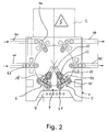
- the reference numeral 1 denotes a support table in FIG. 1 which is adjacent to an electrical switching and control devices receiving cabinet 2 is arranged and for accommodating a general device for processing of, designated 3 Gears is used.
- the reference number 4 indicates a control panel.
- Monitor device housed, via which e.g. Operator guidance information can be displayed are.
- the gear processing device 3 comprises two processing stations 5 and 6, which only the processing station 5 is visible in the side view of FIGS. 1 and 3.
- each processing station is a pneumatic lifting cylinder 7 with a piston rod 8 arranged which are movable in the directions indicated by arrow 9 is.
- the reference number 10 in the figures is a clockwise via a motor transmission unit 11 rotatable plate referred to on which evenly distributed over a circumference six Guides 12 are arranged with lifting plungers 13 displaceable therein.
- the stamp 13 have a stamp head part 14 provided with a support end face 50, which via a spring 15 against a guide part 16 lying against the inside of the guide 12 is cushioned.
- the reference numbers 17 and 18 designate removable frames, each of which is a carrier plate 19, on which machining gears 20 to 22 are rotatably mounted on one side are.
- the change frame 17 and 18 are in producing a releasable connection a mounting frame 23 shown only in Fig. 1 insertable.
- the gear 21 is gimbaled and the gear 22 in an elongated hole 24 within the carrier plate 19 and a guide 52 via a Printing cylinder 25 with a piston rod 26 according to the arrow 27 perpendicular to it Rotary axis can be moved back and forth.
- the machining gear 22 is via one in the figures Invisible polygon plug-in coupling with a drive shaft 28 of a drive motor 29 connected, the drive shaft and the drive motor 29 via the piston rod 26 are reciprocable together with the gear 22.
- the machining gear 22 vertically displaceable on the support plate 19 attached that it is made after insertion of the removable frame in the carrier 23 the coupling connection with the drive shaft 28 and raised by the screw shown can be attached.
- the machining gear connected to the drive shaft 28 via a polygon plug-in coupling 22 is attached to the drive shaft 28 by a central screw, not shown.
- the reference number 30 denotes a guide attached to the frame 23, in which a Stamp 31 is guided, which has an end face 51, which in the same way as that End face 50 of the stamp heads 14 is shaped.
- End face of the punch 31 acts on a peripheral surface of an eccentric 32, which can be driven to rotate via a motor 33.
- the reference numeral 34 denotes a protective cover in FIGS. 1 and 3. In the area covered by the protective cover 34 is not located shown devices for the delivery of processing fluids, especially cooling and Lubricant.
- a liquid drainage system for draining used Machining liquid in a collecting guide 36 denotes from where the liquid arrives in a drip pan 37 comprising a sink.
- a pressure source for the pressure cylinders 7 and 25 is shown.
- the reference numerals 40 and 41 in FIG. 2 are feeds for workpiece toothed wheels 43 referred to get over the workpiece gears on the rotary plate 10.
- removal devices 44 and 45 are provided for removal of workpieces 43 from the rotary plate 10.
- Each of the feed and discharge devices 40, 41, 44, 45 adjoins the rotating plate 10 has a separating device 46.
- Workpiece gearwheels 43 delivered via the feeders 40 and 41 are used in the separating devices 46 out on the rotary plate 10 and with an end face on the Support surfaces 50 of the stamp heads 14 placed.
- the gears are on the respective Stamp heads 14 arranged centered.
- the machining stations can have sets of different machining gears 20 to 22 have, so that supplied via the feeds 40 and 41, possibly different workpiece gears processed differently.
- the pressure cylinder 7 is actuated, the piston rod 8 engages the guide part 16 of the plunger 13 and the plunger 13 with the workpiece gear 43 seated in a position between the machining gears 20 to 22 lifts.
- the machining gear 43 comes with its Contact surface 50 facing away from the end face in abutment against the counter abutment surface 51 of the Stamp 31
- the machining gear 22 Before machining the workpiece gear 43, the machining gear 22 is over the Printing cylinder 25 pressed against the other machining gears 20 and 21. Then be the drive motors 29 and 33 put into operation, the drive motor 29 the machining gear 22 drives for rotation and a rotation of the Workpiece gear 23 and the other rotatably mounted machining gears 20 and 21 causes.
- the spring 15 in the punch 13 By rotating the eccentric 32 driven by the motor 33, the Stamp 31 together with the lifting stamp 13 and the workpiece gear 43 back and forth moves, the spring 15 in the punch 13 provides such a bias that the Stamp 31 constantly in contact with the eccentric 32 during its back and forth movement remains.
- the frequency of the vertical reciprocation of the workpiece gear 43 is in the shown embodiment predetermined.
- the processing time and the contact pressure the machining gears 20 to 22, on the other hand, can be adjusted as required.
- Lubrication system maintains a constant temperature of the smoothing wheels and Processing residues are reliably removed. These measures will in particular achieves a high level of machining accuracy.
- the workpiece toothed wheels 43 are lowered via the pressure cylinder 7, after the motors 29 and 33 shut down and the machining gear 22 over the pressure cylinder 25 has been withdrawn from the workpiece gear 43.
- the motor gear unit 11 now rotates the rotary plate 10 again two cycles, so that the machined gears in a starting position in front of the exhaust devices 44 and 45 arrive from where the processed ones are automatically removed Workpiece gears 43 takes place.
- the machine shown is particularly for reworking due to damage discarded workpiece gears suitable and designed for three-shift operation.
- the machine shown can be equipped with a parts and direction detection system which ensures that only workpiece gears on which the machine is set up to be fed correctly.
- position monitoring be provided by which e.g. the exact fit of the parts on the contact surfaces 50 the punch 13 is checked and the machine is stopped when the parts are not in the intended arrangement position.
- the cooling and lubrication system for cooling, lubrication and cleaning used liquid is via the guide devices 35 and 36 of the drip pan 37 supplied, where regeneration of the liquid takes place via a chip extraction system. This is recorded by an automatic belt filter with a magnetic filter roller Dirt particles separated out.
- the filling quantity of the storage container can automatically monitored and automatically when an adjustable minimum quantity is reached an error message is issued and the machine is shut down.
- the jack could 13 are provided horizontally displaceable, during which displacement the raised workpiece gear 43 through the machining gear 22 to the machining gears 20 and 21 is supplied.
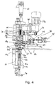
- FIGS. 4 to 6 differs from the previous one Embodiment, inter alia, in that on a rotary plate 10a not lifting stamp, but only pockets 60 for receiving supplied gears to be machined 43a are provided. To adapt to different gear diameters Different sized pockets are provided for converting the processing device are interchangeable.
- a flat support surface for a lifting gear having a workpiece gear 13a Guides 12a are provided, which are moved by a movement device, not shown an axis of rotation 61 can be rotated, with a respective lifting ram 13a with its Guide 12a can be coupled to a cylinder 7a with a piston rod 8a.
- the piston rod 8a engages in the guide 12a with a bearing against a guide part 16a of the lifting ram 13a.
- the guide member 16a is cushioned against a stamp head part 14a via a spring 15a.
- a flat workpiece gear bearing surface having counter-punches 31a provided with guides 30a, which are rotatable about an axis 62 and optionally to a crank oscillation device 63 can be coupled, with a push rod 85 engaging in the guide 30a Crank drive 63 comes to rest against the punch 31a.
- a push rod 85 engaging in the guide 30a Crank drive 63 comes to rest against the punch 31a.
- Each of the processing stations 5a and 6a has a carrier plate designed as an interchangeable frame 19a on which machining gears 20a and 21a are gimbaled are.
- the carrier plate 19a is linear along carrier rails 67 and 68 via a toggle lever 69 displaceable, which is articulated in a recess on a support plate 19a Part 70 engages.
- a third machining gear 22a of the respective machining stations 5a and 6a is on a lever 71, which is pivoted about an axis 72 via a lever 73 at 73 Power cylinder 74 is pivotable.
- the power cylinder 74 is in turn on a bracket 75 hinged.
- the lever 71 has an engagement part 76 which is connected to the toggle lever 69 the side of its fulcrum opposite the part 70 is engaged.
- the machining gear 22a is on a drive shaft 77 mounted on the lever 71 mounted, which via a toothed belt drive 78 by a likewise on the lever 71st attached motor 29a is driven.
- the respective punch 31a is cushioned against its guide 30a by a spring 79.
- reference numeral 80 denotes a each processing station 5a, 6a designated printing cylinder.
- the impression cylinder 80 is articulated at 81 to a swivel drive 82 which, in connection with the the axis 62 rotatable stamps 31a or their guides 30a.
- the swivel drive can be rotated by about 90 °.
- the swivel drive 81 is in turn rotatable by ⁇ 90 ° so that each of the four punches 31a is in the working position can be brought.
- Reference number 83 denotes a drive motor provided for each processing station 5a, 6a referred to, which is connected to the crank drive 63.
- the motor 83 and the crank drive 63 are together on vertical guides 84 and 85 supported and vertically displaceable along these guides via pressure cylinders, not shown and lockable at different heights.
- Means for rotating corresponding to the pressure cylinder 80 and the swivel drive 82 the four punches 13a about the axis of rotation 61 are not shown in the figures.
- a gear wheel can enter one of the processing stations 5a, 6a are moved.
- the movement devices were 80 and 82 for the stamp 31a and the movement devices, not shown for the stamp 13a from the four stamps on the respective gear in the Stamp size adjusted stamp selected.
- the selected punch 13a is lifted over the lifting cylinder 7a, thereby closing it processing gear 43a lifts out of the pocket 60 and into the processing position between the gears 20a to 22a.
- the machining gears 20a which are initially still removed from the workpiece gear 43a to 22a are now brought into engagement with the workpiece gear 43a by the Printing cylinder 74 of the lever 71 pivots and thus the machining gear 22a in the direction is moved to the workpiece gear 43a.
- the support plate 19a moves linearly along the guide rails 67 and 68, whereby the machining gears 20a and 21a are simultaneously engaged with the gear 22a with the workpiece gear 43a.
- the drive motor 29a For machining the workpiece gear 43a between the machining gears 20a to 22a, the drive motor 29a is started, which is via the toothed belt drive 78 and shaft 77 rotates machining gear 22 coupled to shaft 77. At the same time the motor 83 is put into operation, which for the a rocking motion of the punch 31a abutting against the work gear 43 provides, this swinging movement on the machining gear 43a and by the Spring 15a biased punch 13a pressing against the workpiece gear 43a is transmitted.
- the spring 79 ensures a certain damping of the spring movement of the stamp 31a.
- the lever 71 is in the opposite direction via the pressure cylinder 74 Direction pivoted, the machining gears 20a to 22a out of engagement be brought with the workpiece gear 43, the gear 22a by the lever 71 on a circular path and the gears 20a and 21a linear along the guide 67 and 68 be moved.
- the possibility of height adjustment of the punch 31a enables gear wheel machining performed at different heights above the rotating plate 10a and thus e.g. Multiple gears, which have different serrations along their axis of rotation, processed become.
- the drive motors 83 can so far with the crank device 63 raised that the push rod 85 is pulled out of the guide 30a and thus there is freedom of movement for a stamp change.
Landscapes
- Engineering & Computer Science (AREA)
- Mechanical Engineering (AREA)
- Gear Processing (AREA)
Abstract
Description
- Fig. 1
- ein Ausführungsbeispiel für eine erfindungsgemäße Bearbeitungsvorrichtung für Zahnräder in einer teilweise geschnittenen Seitenansicht,
- Fig. 2
- die Vorrichtung von Fig. 1 in einer Draufsicht,
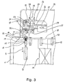
- Fig. 3
- einen Ausschnitt aus der Seitenansicht von Fig. 1,
- Fig. 4
- ein weiteres Ausführungsbeispiel für eine erfindungsgemäße Bearbeitungsvorrichtung in einer Teilseitenansicht,
- Fig. 5
- das Ausführungsbeispiel von Fig. 4 in einem die Bearbeitungszahnräder enthaltenden Horizontalschnitt, und
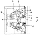
- Fig. 6
- das Ausführungsbeispiel von Fig. 4 und 5 in einer Draufsicht.
Claims (21)
- Vorrichtung zur Bearbeitung von Zahnrädern, mit einer Bearbeitungsstation (5,6), in der ein zu bearbeitendes Werkstückzahnrad (43) in einer Bearbeitungsposition zwischen mehreren, an verschiedenen Umfangspositionen in das Werkstückzahnrad (43) eingreifenden, drehbaren Bearbeitungszahnrädern (20-22) plazierbar ist, sowie mit einer Bewegungseinrichtung zum Befördern des Werkstückzahnrads (43) in die Bearbeitungsposition,
dadurch gekennzeichnet,
daß die Bewegungseinrichtung eine zum Befördern des Werkstückzahnrads (43) in die Bearbeitungsposition in Richtung der Zahnraddrehachsen bewegbare Aufnahmeeinrichtung für das Werkstückzahnrad umfaßt. - Vorrichtung nach Anspruch 1,
dadurch gekennzeichnet,
daß die Aufnahmeeinrichtung eine Anlagefläche, insbesondere Auflagefläche (50), gegen welche das Werkstückzahnrad (43) stirnseitig anlegbar ist, umfaßt. - Vorrichtung nach Anspruch 2,
dadurch gekennzeichnet,
daß die Anlagefläche (50) eine das Werkstückzahnrad (43) zentrierende Formung aufweist oder eben ist. - Vorrichtung nach Anspruch 2 oder 3,
dadurch gekennzeichnet,
daß die Anlagefläche (50) als Stirnfläche eines bewegbaren Stempels, insbesondere Hubstempels (13), für das Werkstückzahnrad (43) gebildet ist. - Vorrichtung nach einem der Ansprüche 2 bis 4,
dadurch gekennzeichnet,
daß in der Bearbeitungsposition das Werkstückzahnrad (43) gegen die Anlagefläche (50) und mit seiner anderen Stirnseite an einer Gegenanlagefläche (51) anliegt. - Vorrichtung nach einem der Ansprüche 1 bis 5,
dadurch gekennzeichnet,
daß eine Einrichtung zur Hin- und Herbewegung des Werkstückzahnrades (43) an der Bearbeitungsposition in Richtung der Zahnradachsen vorgesehen ist. - Vorrichtung nach Anspruch 5 oder 6,
dadurch gekennzeichnet,
daß die Gegenanlagefläche (51) als Stirnfläche eines über einen Exzenterantrieb (32) oder Kurbelantrieb (63) hin und her bewegbaren Stempels (31) und die Anlagefläche (50) gegen das Werkstückzahnrad (43), vorzugsweise über eine Feder (15), vorgespannt ist. - Vorrichtung nach Anspruch 7,
dadurch gekennzeichnet,
daß die Spannfeder (15) zwischen einem die Anlagefläche (50) aufweisenden Stempelkopfteil (14) und einem Stempelführungsteil (16) angeordnet ist. - Vorrichtung nach einem der Ansprüche 1 bis 8,
dadurch gekennzeichnet,
daß die Bewegungseinrichtung eine Transporteinrichtung (10) zum Antransport von Werkstückzahnrädern (43) in eine bei einer Bearbeitungsstation (5,6) gelegene Ausgangsposition, für die Weiterbeförderung in der genannten axialen Richtung in die Bearbeitungsposition, aufweist. - Vorrichtung nach Anspruch 9,
dadurch gekennzeichnet,
daß die Transporteinrichtung (10) zum Antransport der Werkstückzahnräder (43) auf einem Transportweg vereinzelt im Abstand zueinander vorgesehen und entlang dem Transportweg entsprechend dem Abstand mehrere Bearbeitungsstationen (5,6) angeordnet sind. - Vorrichtung nach Anspruch 10,
dadurch gekennzeichnet,
daß die Transporteinrichtung mit Einrichtungen zur Lagefixierung der Werkstückzahnräder versehen ist. - Vorrichtung nach einem der Ansprüche 9 bis 11,
dadurch gekennzeichnet,
daß die Transporteinrichtung einen die Werkstückzahnräder (43) auf einer Kreisbahn antransportierenden Drehplatte (10) umfaßt. - Vorrichtung nach Anspruch 12,
dadurch gekennzeichnet,
daß die Lagefixiereinrichtungen jeweils durch die zentrierenden Auflageflächen (50) eines Hubstempels (13), wobei an der Drehplatte (10) über den Kreisumfang verteilt Führungen (12) für jeweils einen Hubstempel (13) vorgesehen sind, oder durch auf der Drehplatte (10a) angeordnete, zur Anpassung an unterschiedliche Werkstückzahnradgrößen vorzugsweise austauschbare Taschen (60) gebildet sind. - Vorrichtung nach einem der Ansprüche 9 bis 13,
dadurch gekennzeichnet,
daß an der Bearbeitungsstation (5,6) unterhalb der Transporteinrichtung (10) eine Hubantriebseinrichtung (7) für den in der Führung (12) verschiebbaren Hubstempel (13) angeordnet ist. - Vorrichtung nach einem der Ansprüche 1 bis 14,
dadurch gekennzeichnet,
daß die Bearbeitungszahnräder wenigstens zum Teil in einem an der Bearbeitungsstation (5,6) lösbar montierten Wechselrahmen (17,18) gelagert sind. - Vorrichtung nach Anspruch 15,
dadurch gekennzeichnet,
daß der Wechselrahmen (17,18) eine Halterungsplatte (19) zur einseitigen Lagerung der Bearbeitungszahnräder (20-22) mit einer zentralen Öffnung (52) für den Eingriff des die Gegenanlagefläche (51) aufweisenden Stempels (31) umfaßt. - Vorrichtung nach Anspruch 15 oder 16,
dadurch gekennzeichnet,
daß eines (22) von drei in dem Wechselrahmen gelagerten Bearbeitungszahnrädern (20-22) in einer Richtung senkrecht zu seiner Drehachse zum Drücken des Werkstückzahnrads (43) in der Bearbeitungsposition gegen die anderen Bearbeitungszahnräder (20,21) verschiebbar ist. - Vorrichtung nach einem der Ansprüche 15 bis 17,
dadurch gekennzeichnet,
daß wenigstens eines (21;20a,21a) von in dem Wechselrahmen (17,18) gelagerten Bearbeitungszahnrädern (20-23) kardanisch gelagert ist. - Vorrichtung nach einem der Ansprüche 14 bis 18,
dadurch gekennzeichnet,
daß an einer Bearbeitungsstation (5a,6a) zur Anpassung an unterschiedliche Werkstückzahnradgrößen mehrere, die Anlage- und Gegenanlagefläche bildende Stempelpaare (13a,31a) vorgesehen und die Stempel (13a) der Paare wahlweise an die Hubantriebseinrichtung (7a) zum Befördern des Werkstückzahnrads in die Bearbeitungsposition sowie an die Einrichtung (63) zur Hin- und Herbewegung des Werkstückzahnrads an der Bearbeitungsposition ankoppelbar ist. - Vorrichtung nach Anspruch 19,
dadurch gekennzeichnet,
daß eines (22a) von drei Bearbeitungszahnrädern (20a bis 22a) an einem zum Befördern dieses Zahnrads (22a) in Eingriff mit dem Werkstückzahnrad (43a) schwenkbaren Hebel (71) gelagert ist, und die anderen Bearbeitungszahnräder (20,21a) an einer zum Eingriff mit dem Werkstückzahnrad (43a) linear über einen mit dem Hebel (71) zusammenarbeitenden Kniehebel (69) linear verschiebbaren Trägerhalterung (19a), die insbesondere als Wechselrahmen ausgebildet ist, gelagert sind. - Vorrichtung nach einem der Ansprüche 19 oder 20,
dadurch gekennzeichnet,
daß die Höhe der Bearbeitungsposition über der Drehplatte (10a) verstellbar ist.
Applications Claiming Priority (2)
| Application Number | Priority Date | Filing Date | Title |
|---|---|---|---|
| DE1997142514 DE19742514A1 (de) | 1997-09-26 | 1997-09-26 | Vorrichtung zur Bearbeitung von Zahnrädern |
| DE19742514 | 1997-09-26 |
Publications (2)
| Publication Number | Publication Date |
|---|---|
| EP0904878A2 true EP0904878A2 (de) | 1999-03-31 |
| EP0904878A3 EP0904878A3 (de) | 2003-09-10 |
Family
ID=7843714
Family Applications (1)
| Application Number | Title | Priority Date | Filing Date |
|---|---|---|---|
| EP98117803A Withdrawn EP0904878A3 (de) | 1997-09-26 | 1998-09-19 | Zahnräderbearbeitungsvorrichtung mit Werkstückbeförderungsvorrichtung |
Country Status (2)
| Country | Link |
|---|---|
| EP (1) | EP0904878A3 (de) |
| DE (1) | DE19742514A1 (de) |
Cited By (2)
| Publication number | Priority date | Publication date | Assignee | Title |
|---|---|---|---|---|
| FR2850044A1 (fr) * | 2001-07-24 | 2004-07-23 | Minitec For Better Gears Gmbh | Dispositif pour le polissage de roues dentees |
| EP1992439A1 (de) | 2007-05-12 | 2008-11-19 | Kapp GmbH | Hartfeinbearbeitungsmaschine |
Family Cites Families (6)
| Publication number | Priority date | Publication date | Assignee | Title |
|---|---|---|---|---|
| GB707834A (en) * | 1952-05-26 | 1954-04-21 | Gaston Emile Henry Marbaix | Machines for cutting, grinding, polishing and otherwise treating circular components |
| US4067218A (en) * | 1976-12-16 | 1978-01-10 | Bibbens William H | Apparatus and method and means for removing surface defects from a workpiece |
| DE2912545C2 (de) * | 1979-03-29 | 1984-09-27 | Carl Hurth Maschinen- und Zahnradfabrik GmbH & Co, 8000 München | Maschine zum Feinbearbeiten der Zahnflanken von verzahnten Werkstücken |
| JPS6039487B2 (ja) * | 1980-07-02 | 1985-09-06 | ル−ドルフ商会株式会社 | ロ−デイング装置 |
| US4309802A (en) * | 1980-07-16 | 1982-01-12 | Illinois Tool Works Inc. | Ring gear burnishing machine |
| US5272897A (en) * | 1992-05-12 | 1993-12-28 | Engineered Abrasives, Inc. | Part hold down apparatus for part processing machine |
-
1997
- 1997-09-26 DE DE1997142514 patent/DE19742514A1/de not_active Withdrawn
-
1998
- 1998-09-19 EP EP98117803A patent/EP0904878A3/de not_active Withdrawn
Cited By (5)
| Publication number | Priority date | Publication date | Assignee | Title |
|---|---|---|---|---|
| FR2850044A1 (fr) * | 2001-07-24 | 2004-07-23 | Minitec For Better Gears Gmbh | Dispositif pour le polissage de roues dentees |
| EP1992439A1 (de) | 2007-05-12 | 2008-11-19 | Kapp GmbH | Hartfeinbearbeitungsmaschine |
| JP2008279594A (ja) * | 2007-05-12 | 2008-11-20 | Kapp Gmbh | ワークの精密仕上げのための精密加工装置 |
| US7632172B2 (en) | 2007-05-12 | 2009-12-15 | Kapp Gmbh | Hard finishing machine |
| CN101337294B (zh) * | 2007-05-12 | 2011-11-09 | Kapp有限公司 | 硬质面精加工机床 |
Also Published As
| Publication number | Publication date |
|---|---|
| EP0904878A3 (de) | 2003-09-10 |
| DE19742514A1 (de) | 1999-04-15 |
Similar Documents
| Publication | Publication Date | Title |
|---|---|---|
| DE2760355C2 (de) | ||
| DE2902197C2 (de) | ||
| DE2623924A1 (de) | Montagemaschine fuer schraubenrohlinge und scheiben | |
| DE3440224C2 (de) | Werkzeugwechselvorrichtung an einer Stanz- oder Nibbelmaschine | |
| DE69000888T2 (de) | Verfahren und vorrichtung zum abschraegen von einspringenden ecken bei tafeln aus farbigem oder nicht farbigem flachglas. | |
| DE2753801A1 (de) | Verfahren und vorrichtung zum auswechseln von werkzeugkoepfen an werkzeugmaschinen | |
| DE2131257A1 (de) | Verfahren und Vorrichtung zum Zusammensetzen von Scheiben mit Schrauben | |
| EP3650213B1 (de) | Tablettenpresse und verfahren zum herstellen einer tablette | |
| DE69103111T2 (de) | Automatische Hobelmaschine. | |
| EP0470961B1 (de) | Proben-aufbereitungssystem für eisen- und stahlproben | |
| DE3523239C2 (de) | Vorrichtung zum gleichzeitigen Polieren der Wellenabschnitte und Stirnflächen und zum Abfasen der Zahnkanten von Ritzelwellen | |
| DE2851156A1 (de) | Sicherheitsvorrichtung fuer eine presse o.dgl. | |
| DE3613170C2 (de) | Automatische Entgratmaschine | |
| EP0904878A2 (de) | Zahnräderbearbeitungsvorrichtung mit Werkstückbeförderungsvorrichtung | |
| DE470864C (de) | Maschine zum selbsttaetigen Zerteilen eines ununterbrochen fortlaufenden Rohres oder Stabes aus Glas in einzelne Abschnitte | |
| DE69701828T2 (de) | Vorrichtung zum automatischen Zuführen von Borstenbehältern oder Borstenkassetten für Bürstenherstellungsmaschinen | |
| DE3922532C1 (de) | ||
| EP0478903A1 (de) | Wechselkassettenvorrichtung für eine Rollenrotationsdruckmaschine | |
| CH665159A5 (de) | Schleifmaschine. | |
| DE10001758A1 (de) | Räummaschine | |
| DE3907687A1 (de) | Stanzmaschine | |
| DE3425317C2 (de) | ||
| EP0407657B1 (de) | Staucheinrichtung zum Stauchen der Enden länglicher Werkstücke wie Drahtstücke und Verwendung einer solchen Einrichtung in einer drahtverarbeitenden Stiftpresse | |
| DE3831158A1 (de) | Werkzeugmaschine | |
| DE3517764C2 (de) |
Legal Events
| Date | Code | Title | Description |
|---|---|---|---|
| PUAI | Public reference made under article 153(3) epc to a published international application that has entered the european phase |
Free format text: ORIGINAL CODE: 0009012 |
|
| AK | Designated contracting states |
Kind code of ref document: A2 Designated state(s): AT BE CH CY DE DK ES FI FR GB GR IE IT LI LU MC NL PT SE |
|
| AX | Request for extension of the european patent |
Free format text: AL;LT;LV;MK;RO;SI |
|
| RIN1 | Information on inventor provided before grant (corrected) |
Inventor name: MUELLER, PETER Inventor name: JAKOBY, HERBERT |
|
| RAP1 | Party data changed (applicant data changed or rights of an application transferred) |
Owner name: MINITEC GMBH LINEARANTRIEBSANHEITEN ALU-MONTAGESYS |
|
| RAP3 | Party data changed (applicant data changed or rights of an application transferred) |
Owner name: MINITEC GMBH LINEARANTRIEBSEINHEITEN ALU-MONTAGESY |
|
| PUAL | Search report despatched |
Free format text: ORIGINAL CODE: 0009013 |
|
| AK | Designated contracting states |
Kind code of ref document: A3 Designated state(s): AT BE CH CY DE DK ES FI FR GB GR IE IT LI LU MC NL PT SE |
|
| AX | Request for extension of the european patent |
Extension state: AL LT LV MK RO SI |
|
| AKX | Designation fees paid |
Designated state(s): CH DE FR GB LI |
|
| STAA | Information on the status of an ep patent application or granted ep patent |
Free format text: STATUS: THE APPLICATION IS DEEMED TO BE WITHDRAWN |
|
| 18D | Application deemed to be withdrawn |
Effective date: 20040311 |