EP0904728B1 - Implantierbarer Druckanzeiger - Google Patents
Implantierbarer Druckanzeiger Download PDFInfo
- Publication number
- EP0904728B1 EP0904728B1 EP98307901A EP98307901A EP0904728B1 EP 0904728 B1 EP0904728 B1 EP 0904728B1 EP 98307901 A EP98307901 A EP 98307901A EP 98307901 A EP98307901 A EP 98307901A EP 0904728 B1 EP0904728 B1 EP 0904728B1
- Authority
- EP
- European Patent Office
- Prior art keywords
- pressure
- housing
- marking
- scale
- position indicating
- Prior art date
- Legal status (The legal status is an assumption and is not a legal conclusion. Google has not performed a legal analysis and makes no representation as to the accuracy of the status listed.)
- Expired - Lifetime
Links
- 239000012530 fluid Substances 0.000 claims description 46
- 239000007789 gas Substances 0.000 claims description 34
- 239000000463 material Substances 0.000 claims description 34
- 238000009530 blood pressure measurement Methods 0.000 claims description 22
- 238000003384 imaging method Methods 0.000 claims description 15
- 239000003570 air Substances 0.000 claims description 12
- 230000008878 coupling Effects 0.000 claims description 7
- 238000010168 coupling process Methods 0.000 claims description 7
- 238000005859 coupling reaction Methods 0.000 claims description 7
- IJGRMHOSHXDMSA-UHFFFAOYSA-N Atomic nitrogen Chemical compound N#N IJGRMHOSHXDMSA-UHFFFAOYSA-N 0.000 claims description 6
- 210000001124 body fluid Anatomy 0.000 claims description 3
- 229910052757 nitrogen Inorganic materials 0.000 claims description 3
- QVGXLLKOCUKJST-UHFFFAOYSA-N atomic oxygen Chemical compound [O] QVGXLLKOCUKJST-UHFFFAOYSA-N 0.000 claims description 2
- 238000004891 communication Methods 0.000 claims description 2
- 239000001301 oxygen Substances 0.000 claims description 2
- 229910052760 oxygen Inorganic materials 0.000 claims description 2
- 210000001175 cerebrospinal fluid Anatomy 0.000 description 22
- 238000007917 intracranial administration Methods 0.000 description 21
- 238000007789 sealing Methods 0.000 description 16
- 238000002513 implantation Methods 0.000 description 15
- RTAQQCXQSZGOHL-UHFFFAOYSA-N Titanium Chemical compound [Ti] RTAQQCXQSZGOHL-UHFFFAOYSA-N 0.000 description 10
- 229910052751 metal Inorganic materials 0.000 description 10
- 239000002184 metal Substances 0.000 description 10
- 239000010936 titanium Substances 0.000 description 10
- 229910052719 titanium Inorganic materials 0.000 description 10
- 230000007246 mechanism Effects 0.000 description 8
- 229920001296 polysiloxane Polymers 0.000 description 8
- -1 titanium Chemical class 0.000 description 8
- 230000036760 body temperature Effects 0.000 description 6
- 230000008859 change Effects 0.000 description 6
- 239000007788 liquid Substances 0.000 description 6
- FAPWRFPIFSIZLT-UHFFFAOYSA-M Sodium chloride Chemical compound [Na+].[Cl-] FAPWRFPIFSIZLT-UHFFFAOYSA-M 0.000 description 5
- 238000011961 computed axial tomography Methods 0.000 description 5
- 230000013011 mating Effects 0.000 description 5
- 239000011780 sodium chloride Substances 0.000 description 5
- 229910001069 Ti alloy Inorganic materials 0.000 description 4
- TZCXTZWJZNENPQ-UHFFFAOYSA-L barium sulfate Chemical compound [Ba+2].[O-]S([O-])(=O)=O TZCXTZWJZNENPQ-UHFFFAOYSA-L 0.000 description 4
- 210000004556 brain Anatomy 0.000 description 4
- 230000007423 decrease Effects 0.000 description 4
- 238000012977 invasive surgical procedure Methods 0.000 description 4
- 238000002595 magnetic resonance imaging Methods 0.000 description 4
- 239000012528 membrane Substances 0.000 description 4
- 150000002739 metals Chemical class 0.000 description 4
- 238000012544 monitoring process Methods 0.000 description 4
- 229920000642 polymer Polymers 0.000 description 4
- 230000004044 response Effects 0.000 description 4
- 239000010935 stainless steel Substances 0.000 description 4
- 229910001220 stainless steel Inorganic materials 0.000 description 4
- 239000004698 Polyethylene Substances 0.000 description 3
- 241001417494 Sciaenidae Species 0.000 description 3
- 230000036772 blood pressure Effects 0.000 description 3
- 210000001035 gastrointestinal tract Anatomy 0.000 description 3
- 238000004519 manufacturing process Methods 0.000 description 3
- 238000005259 measurement Methods 0.000 description 3
- 229920000573 polyethylene Polymers 0.000 description 3
- 239000005020 polyethylene terephthalate Substances 0.000 description 3
- 229920000139 polyethylene terephthalate Polymers 0.000 description 3
- 229920002635 polyurethane Polymers 0.000 description 3
- 239000004814 polyurethane Substances 0.000 description 3
- 229910052715 tantalum Inorganic materials 0.000 description 3
- GUVRBAGPIYLISA-UHFFFAOYSA-N tantalum atom Chemical compound [Ta] GUVRBAGPIYLISA-UHFFFAOYSA-N 0.000 description 3
- 238000002604 ultrasonography Methods 0.000 description 3
- 230000002861 ventricular Effects 0.000 description 3
- XKRFYHLGVUSROY-UHFFFAOYSA-N Argon Chemical compound [Ar] XKRFYHLGVUSROY-UHFFFAOYSA-N 0.000 description 2
- ZOXJGFHDIHLPTG-UHFFFAOYSA-N Boron Chemical compound [B] ZOXJGFHDIHLPTG-UHFFFAOYSA-N 0.000 description 2
- 229910000684 Cobalt-chrome Inorganic materials 0.000 description 2
- 229910052688 Gadolinium Inorganic materials 0.000 description 2
- VVQNEPGJFQJSBK-UHFFFAOYSA-N Methyl methacrylate Chemical compound COC(=O)C(C)=C VVQNEPGJFQJSBK-UHFFFAOYSA-N 0.000 description 2
- 239000004695 Polyether sulfone Substances 0.000 description 2
- MCMNRKCIXSYSNV-UHFFFAOYSA-N ZrO2 Inorganic materials O=[Zr]=O MCMNRKCIXSYSNV-UHFFFAOYSA-N 0.000 description 2
- 229910045601 alloy Inorganic materials 0.000 description 2
- 239000000956 alloy Substances 0.000 description 2
- PNEYBMLMFCGWSK-UHFFFAOYSA-N aluminium oxide Inorganic materials [O-2].[O-2].[O-2].[Al+3].[Al+3] PNEYBMLMFCGWSK-UHFFFAOYSA-N 0.000 description 2
- 230000003466 anti-cipated effect Effects 0.000 description 2
- 229910052788 barium Inorganic materials 0.000 description 2
- DSAJWYNOEDNPEQ-UHFFFAOYSA-N barium atom Chemical compound [Ba] DSAJWYNOEDNPEQ-UHFFFAOYSA-N 0.000 description 2
- 239000000560 biocompatible material Substances 0.000 description 2
- 210000000988 bone and bone Anatomy 0.000 description 2
- 229910052796 boron Inorganic materials 0.000 description 2
- 239000010952 cobalt-chrome Substances 0.000 description 2
- 230000006835 compression Effects 0.000 description 2
- 238000007906 compression Methods 0.000 description 2
- UIWYJDYFSGRHKR-UHFFFAOYSA-N gadolinium atom Chemical compound [Gd] UIWYJDYFSGRHKR-UHFFFAOYSA-N 0.000 description 2
- 208000003906 hydrocephalus Diseases 0.000 description 2
- 229910052588 hydroxylapatite Inorganic materials 0.000 description 2
- 201000009941 intracranial hypertension Diseases 0.000 description 2
- 229920002529 medical grade silicone Polymers 0.000 description 2
- 239000000203 mixture Substances 0.000 description 2
- RVTZCBVAJQQJTK-UHFFFAOYSA-N oxygen(2-);zirconium(4+) Chemical compound [O-2].[O-2].[Zr+4] RVTZCBVAJQQJTK-UHFFFAOYSA-N 0.000 description 2
- XYJRXVWERLGGKC-UHFFFAOYSA-D pentacalcium;hydroxide;triphosphate Chemical compound [OH-].[Ca+2].[Ca+2].[Ca+2].[Ca+2].[Ca+2].[O-]P([O-])([O-])=O.[O-]P([O-])([O-])=O.[O-]P([O-])([O-])=O XYJRXVWERLGGKC-UHFFFAOYSA-D 0.000 description 2
- 229920006393 polyether sulfone Polymers 0.000 description 2
- 229920001343 polytetrafluoroethylene Polymers 0.000 description 2
- 239000004810 polytetrafluoroethylene Substances 0.000 description 2
- 206010002329 Aneurysm Diseases 0.000 description 1
- 229920002799 BoPET Polymers 0.000 description 1
- 239000005041 Mylar™ Substances 0.000 description 1
- 206010062243 Shunt malfunction Diseases 0.000 description 1
- 208000002667 Subdural Hematoma Diseases 0.000 description 1
- 239000004699 Ultra-high molecular weight polyethylene Substances 0.000 description 1
- 238000010521 absorption reaction Methods 0.000 description 1
- 239000000853 adhesive Substances 0.000 description 1
- 230000001070 adhesive effect Effects 0.000 description 1
- 229910052786 argon Inorganic materials 0.000 description 1
- 230000017531 blood circulation Effects 0.000 description 1
- 210000005013 brain tissue Anatomy 0.000 description 1
- 239000002775 capsule Substances 0.000 description 1
- 210000003161 choroid Anatomy 0.000 description 1
- 239000000788 chromium alloy Substances 0.000 description 1
- 230000003920 cognitive function Effects 0.000 description 1
- 230000008602 contraction Effects 0.000 description 1
- 230000001276 controlling effect Effects 0.000 description 1
- 238000007796 conventional method Methods 0.000 description 1
- 238000007428 craniotomy Methods 0.000 description 1
- 230000003247 decreasing effect Effects 0.000 description 1
- 229920001971 elastomer Polymers 0.000 description 1
- 239000000806 elastomer Substances 0.000 description 1
- 230000003028 elevating effect Effects 0.000 description 1
- 239000011888 foil Substances 0.000 description 1
- 230000006870 function Effects 0.000 description 1
- 230000001771 impaired effect Effects 0.000 description 1
- 238000012623 in vivo measurement Methods 0.000 description 1
- 230000006698 induction Effects 0.000 description 1
- 208000015181 infectious disease Diseases 0.000 description 1
- 238000001802 infusion Methods 0.000 description 1
- 230000002452 interceptive effect Effects 0.000 description 1
- 230000007774 longterm Effects 0.000 description 1
- 230000007257 malfunction Effects 0.000 description 1
- 238000000034 method Methods 0.000 description 1
- 230000007659 motor function Effects 0.000 description 1
- 229910052756 noble gas Inorganic materials 0.000 description 1
- 150000002835 noble gases Chemical class 0.000 description 1
- 231100000252 nontoxic Toxicity 0.000 description 1
- 230000003000 nontoxic effect Effects 0.000 description 1
- 230000001575 pathological effect Effects 0.000 description 1
- 239000012857 radioactive material Substances 0.000 description 1
- 230000001105 regulatory effect Effects 0.000 description 1
- 230000008439 repair process Effects 0.000 description 1
- 238000011160 research Methods 0.000 description 1
- 238000005070 sampling Methods 0.000 description 1
- 210000004761 scalp Anatomy 0.000 description 1
- 239000000126 substance Substances 0.000 description 1
- 208000024891 symptom Diseases 0.000 description 1
- 238000003325 tomography Methods 0.000 description 1
- 229920000785 ultra high molecular weight polyethylene Polymers 0.000 description 1
- XLYOFNOQVPJJNP-UHFFFAOYSA-N water Substances O XLYOFNOQVPJJNP-UHFFFAOYSA-N 0.000 description 1
Images


Classifications
-
- A—HUMAN NECESSITIES
- A61—MEDICAL OR VETERINARY SCIENCE; HYGIENE
- A61B—DIAGNOSIS; SURGERY; IDENTIFICATION
- A61B5/00—Measuring for diagnostic purposes; Identification of persons
- A61B5/03—Measuring fluid pressure within the body other than blood pressure, e.g. cerebral pressure ; Measuring pressure in body tissues or organs
- A61B5/031—Intracranial pressure
-
- A—HUMAN NECESSITIES
- A61—MEDICAL OR VETERINARY SCIENCE; HYGIENE
- A61B—DIAGNOSIS; SURGERY; IDENTIFICATION
- A61B5/00—Measuring for diagnostic purposes; Identification of persons
- A61B5/02—Detecting, measuring or recording for evaluating the cardiovascular system, e.g. pulse, heart rate, blood pressure or blood flow
- A61B5/021—Measuring pressure in heart or blood vessels
- A61B5/0215—Measuring pressure in heart or blood vessels by means inserted into the body
-
- A—HUMAN NECESSITIES
- A61—MEDICAL OR VETERINARY SCIENCE; HYGIENE
- A61B—DIAGNOSIS; SURGERY; IDENTIFICATION
- A61B5/00—Measuring for diagnostic purposes; Identification of persons
- A61B5/03—Measuring fluid pressure within the body other than blood pressure, e.g. cerebral pressure ; Measuring pressure in body tissues or organs
- A61B5/036—Measuring fluid pressure within the body other than blood pressure, e.g. cerebral pressure ; Measuring pressure in body tissues or organs by means introduced into body tracts
- A61B5/037—Measuring oesophageal pressure
Definitions
- the present invention relates to pressure measurement devices, and more particularly to an implantable pressure measurement device that provides physiological pressure information via an external imaging system.
- Pressure measurement devices of various types are used to measure a physiological pressure in different areas within the body of a patient.
- One application of such devices is in the treatment of hydrocephalus, a condition where cerebrospinal fluid (CSF) collects in the ventricles of the brain of a patient.
- CSF cerebrospinal fluid
- the volume of CSF increases thereby elevating the intracranial pressure.
- This excess CSF can result in abnormally high epidural and intradural pressures.
- hydrocephalus can result in serious medical conditions, including subdural hematoma, compression of the brain tissue and impaired blood flow that consequently can impair cognitive and motor function.
- a pressure measurement device can be inserted into the patient to measure the pressure.
- One such device is a catheter having a sensor for in vivo measurement of intracranial pressure in which one end of the catheter is disposed in the ventricular region of the brain and the other end exits the cranial region for coupling to a monitor.
- the measurement of intracranial pressure with such a device is an invasive procedure having certain concomitant risks, such as infection and human error.
- monitoring intracranial pressure with this type of device is best suited for short term use only.
- intracranial pressure is above acceptable levels
- the pressure should be relieved.
- Various drainage catheters or shunt systems have been developed to remove the excess CSF and to discharge the fluid to another part of the body, such as the peritoneal region. By draining the excess fluid, the elevated intracranial pressure is reduced.
- CSF shunt systems designed for long term use are implantable within the patient.
- Such CSF shunt systems include a valve mechanism for controlling or regulating the flow rate of fluid through the system.
- An illustrative shunt system includes a valve mechanism in fluid communication with a brain ventricular catheter. The ventricular catheter is inserted into a ventricle of the brain and a peritoneal catheter is inserted into the peritoneal region for discharge of the fluid. While such implanted catheters can drain excess CSF if working properly, intracranial pressure information is not readily available without an invasive surgical procedure.
- Shunt systems typically permit fluid flow only when the fluid pressure reaches a threshold pressure for the shunt valve.
- the threshold pressure that allows fluid flow through a shunt system must sometimes be adjusted. For example, a surgeon may initially select a relatively low threshold pressure to trigger fluid flow. Over time, the initial threshold pressure may not be ideal. For example, it could lead to excess fluid flow, creating an undesirable overdrainage condition caused by too much fluid being drained from the ventricle. A CSF overdrainage condition can result in a dangerously low intracranial pressure. Such a situation may give rise to a need to increase the threshold pressure to afford a fluid flow rate that is balanced to avoid both excessive intracranial pressure and overdrainage conditions.
- Some shunt systems can become clogged or may malfunction mechanically. When a patient exhibits symptoms that could be related to shunt malfunction it is often desirable to evaluate whether the shunt system is functioning properly and/or to evaluate intracranial pressure directly. If the threshold pressure is set too high, or if the valve is occluded, excessive CSF will not be discharged via the shunt system to relieve intracranial pressure. If the threshold pressure of the valve mechanism is set too low, or if the valve is stuck open, a CSF overdrainage condition can occur. Shunt system operation can be monitored by observing the pressure on fluid in the shunt system. However, as discussed above, monitoring the pressure of an implanted shunt system can require an undesirable invasive surgical procedure.
- a pressure sensor for being affixed to a patient's cranium coupled to a tambour via a tube.
- the sensor includes a lower housing plate having a recess for accommodating a flat coil of tubing.
- the coil of tubing has a coupling disposed on an outer end and a coupling disposed on an inner end for connection to a bellows assembly which includes a bellows member and a bellows closure plate.
- the tambour, the pressure tube, and the adjacent portion of the flat coil of tubing are filled with saline.
- the balance of the flat coil of tubing and the entire interior chamber of the closed-end bellows assembly is filled with a radiopaque liquid.
- the saline is immiscible in the radiopaque liquid.
- a pressure increase on the tambour forces saline up through the pressure tube so as to cause the radiopaque liquid to shift within the flat coil of tubing. This shift alters the location of an interface between the saline and the radiopaque liquid.
- the intracranial pressure is determined based on the location of the saline/liquid interface.
- US 4,114,458 there is disclosed a fluid pressure transducer and a tire pressure measuring instrument, which includes the transducer.
- FIGS. 1-3 US 4,114,458 discloses a tire pressure measuring device which includes a pressure transducer.
- the transducer includes a capsule having a first end coupled to a casing and a second end with a line which can be read through a transparent portion of the casing.
- the document US-A-4 231 376 discloses a intracranial pressure monitor having a housing with a conduit (62) and with a flexible member (24) filled with a gas whereby the expanding or contracting gas causes the flexible member to move a shielding tube (50) over a radioactive material (42). A change in pressure is thus detected as a change in externally measured radioactivity.
- the document FR-A-2 325 351 discloses a intracranial pressure monitor with a x-ray imageable flexible member (7) filled with a gas whereby the expanding or contracting gas causes the flexible member to move a magnetic kernel (4) into an oscillating circuit (3). A change in pressure is thus detected as a change in externally measured (via induction) resonantfrequency.
- An implantable pressure measurement device is needed that provides physiological pressure information, without invasive surgical procedures. It would also be desirable to monitor the operation of certain implanted devices, such as fluid shunt systems.
- the present invention provides a pressure measurement device adapted for surgical implantation in the body of a patient that is useful for determining physiological pressures.
- the device can be adapted for implantation by itself, or for coupling to an implantable shunt system.
- the device is primarily described and illustrated in conjunction with measuring intracranial pressure, it is understood that it can be used for measuring other physiological pressures as well, such as blood pressure in the heart or pressure in the gastrointestinal tract.
- a pressure measurement device includes a housing having a passageway leading to a chamber with at least one scale marking disposed on the passageway of the housing.
- a flexible member that contains an amount of gas is disposed within and can axially expand and contract within the chamber.
- a position indicating member having at least one position marking extends from the flexible member and is movable in the passageway. The relative position of the position indicating member with respect to the scale marking is indicative of the volume of the gas in the flexible member. Since the volume of the gas is a function of pressure and temperature, the physiological pressure can be determined based on the measured volume.
- the gas in the flexible member expands or contracts to equalize the pressure on the gas in the flexible member and the external pressure.
- An increase in such external pressure results in compression of the gas in the flexible member.
- the gas contained by the flexible member expands.
- the expansion and contraction of the gas moves the flexible member, thereby altering the location of the position indicating member in the passageway of the housing.
- the position marking migrates with respect to the scale marking on the housing, and the location of the position marking on the scale can be observed with an external imaging system.
- the volume of the gas in the flexible member and the pressure external to the device can be ascertained.
- the differential between the pressure external to the device and ambient pressure represents the physiological pressure at the site of implantation.
- the present invention provides an implantable pressure measurement device that renders physiological pressure information without invasive surgical procedures.
- the device is implantable as a stand-alone unit.
- the device is coupled to an implantable shunt system to monitor pressure of fluid in a shunt system.
- the device can also be coupled to an external drainage system. It is understood that the device can be used in other applications that will be readily apparent to one of ordinary skill in the art, such as monitoring blood pressure and pressure within the gastrointestinal tract.
- the drawings are not to scale and are intended to facilitate an understanding of the invention. Accordingly, the invention is not to be limited to the particular applications and embodiments shown and described herein.
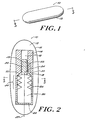
- FIGS. 1-4 show a pressure measurement device 10 adapted for stand-alone implantation at a location in the body of a patient, such as in the cranium.
- the device can be tethered by a flexible chord made of silicone or other biocompatible material that is sutured to a burr hole or craniotomy site.
- An optional covering 12 isolates the device from bodily fluids and the like to prevent biological substances and deposits from interfering with the performance of the device.
- the covering 12 can contain a fluid 13 which can be a biocompatible gas or liquid, such as air.
- the pressure measurement device 10 includes a housing 14 having a passageway or neck 16 extending into a chamber 18.
- the neck 16 can include a tapered portion 20 that widens into the chamber 18.
- At least one scale marking 22 is located on the neck 16 of the housing to form a portion of a scale 24, which is discussed below.
- the flexible member includes a first end 30 and a second end 32 with a bellows portion 34 therebetween.
- the bellows portion 34 readily expands and contracts along a longitudinal axis 37 of the chamber 18.
- the second end 32 of the flexible member can be secured to the chamber 18 to allow maximum extension of the flexible member before the first end 30 abuts the tapered portion 20 of the neck.
- the flexible member 26 generally conforms to the contour of the chamber 18.
- the chamber 18 and the flexible member 26 are generally concentric cylinders.
- the flexible member 26 and the bellows portion 34 have a diameter which is slightly smaller than a diameter of the chamber 18.
- the flexible member 26 is contained within the chamber 18, but the chamber does not impede axial movement of the bellows portion 34.
- the gas 28 in the flexible member can be air, nitrogen, oxygen, or another suitable, preferably non-toxic, gas or fluid.
- a preferred fluid is air.
- the gas 28 can be placed in the flexible member at a known pressure and temperature.
- the gas 28 in the flexible member is initially at atmospheric pressure at the site of assembly and typical body temperature (i.e., 37 degrees C).
- the air is sealed in the flexible member 26 at a pressure of 10400 mm H 2 O at typical body temperature.
- a position indicating member 36 extends from the first end 30 of the flexible member into the housing neck 16.
- the position indicating member 36 can be integral with the flexible member 26 or affixed thereto.
- At least one position marking 38 is disposed on or in the position indicating member 36.
- the position marking 38 forms a portion of the scale 24, which, as described below, indicates the relative position of the position indicating member 36 with respect to the housing 14.
- the scale and position markings 22,38 can be formed from various materials that are discernible, i.e., at least partially opaque, to an imaging system, such as an X-ray, fluoroscope, ultrasound, computed axial tomography (CAT) scan, magnetic resonance imaging (MRI) system, position emission (PET) or other such system.
- an imaging system such as an X-ray, fluoroscope, ultrasound, computed axial tomography (CAT) scan, magnetic resonance imaging (MRI) system, position emission (PET) or other such system.
- Exemplary materials for the scale and position markings 22,38 include radiopaque metals such as titanium, titanium alloys, stainless steel, boron, tantalum, cobalt chrome alloys, gadolinium, barium, and radiopaque materials such as barium sulfate, doped methylmethacrylate, zirconium dioxide, alumina, hydroxyapatite, and processed bone. It is understood that the material to be used must be compatible with a desired imaging system. In an
- the scale and position markings can each be identical in dimension and composition, or they can be unique.
- the markings can sequentially change in dimension or composition in a predetermined pattern that is readily apparent in a corresponding imaging system.
- the markings can sequentially vary in opacity to appear progressively darker when displayed on an imaging system.
- the position markings 38 include four lines spaced at about 1.2 millimeters and the scale markings 22 include 18 lines equally spaced at 1.0 millimeter to form a Vernier scale.
- the dimensions of the various device components can vary. It is important that the relative dimensions of the components be such that the flexible member is axially movable in the chamber with minimal friction or interference.
- the chamber should provide sufficient axial extension to allow movement of the flexible member for an expected pressure range of the device.
- the dimensions of these components will vary depending upon the requirements of a given application and the anticipated site of implantation. One of ordinary skill in the art can readily determine the appropriate relative dimensions of the device components.
- the overall length of the housing 14 can be from about 10 millimeters to about 60 millimeters, and more preferably from about 20 millimeters to about 35 millimeters.
- the housing width can range from about 2 millimeters to about 6 millimeters, and preferably about 4 millimeters.
- the chamber 18 can have a length from about 10.0 millimeters to about 60.0 millimeters and a width of about 1.8 millimeters to about 5.0 millimeters. In one embodiment, the length of the chamber 18 is about 34.0 millimeters and the width is about 4.0 millimeters.
- the device 10 provides non-invasive pressure measurements based on the equalization of the pressure on the gas 28 trapped within the flexible member and a pressure external to the device.
- the external pressure is communicated to the flexible member 26 via the passageway 16 in the housing, thus influencing the location of the position indicating member 36.
- the relative location of the position indicating member 36 is ascertained through the use of an external imaging system (not shown) to determine the location of the position marking 38 as compared to the scale marking 22 on the housing.
- the position of the position indicating member 36 indicates the volume of the gas 28 in the first housing.
- the external pressure is determined from the volume of the gas as described below.
- the bellows portion 34 of the flexible member 26 contracts as the gas is compressed causing the position marking 38 to move in one direction with respect to the scale marking 22.
- the bellows 34 of the flexible member 26 extends to move the position marking 38 in the opposite direction as the gas expands.
- the location of the position marking 38 indicates the differential between the initial volume of gas 28 trapped at manufacture at an initial pressure and the volume of the gas 28 in the presence of an external pressure.
- the device measures gas volume directly and pressure indirectly.
- the gas 28 volume reading is used in conjunction with pressure information to determine a pressure proximate the site of implantation.
- the initial pressure on the gas 28 in the flexible member 26 and initial scale reading are known at the time of assembly. This information is used to determine a relationship between the scale reading and the external pressure. For example, from an initial (assembly) pressure of about 10333 mm H 2 O and initial location of the position indicating member 36 with respect to the scale, the pressure/scale(volume) relationship can be determined. That is, for each location of the position indicating member 36 with respect to the scale, the corresponding external pressure is known.
- the ambient or atmospheric pressure is established at the time and location of device measurements using conventional methods and/or devices.
- a reading of the device provides the volume of the gas 28 which corresponds to an external pressure.
- the ambient pressure is subtracted from the external pressure to obtain the pressure differential, i.e., the pressure at the site of implantation.
- the pressure differential at the site of implantation i.e., intracranial pressure
- a physiological pressure i.e., the pressure differential, is determined by reading the scale to determine the external pressure and subtracting ambient pressure from the external pressure.
- this temperature differential can reduce the accuracy of a device measurement.
- the gas in the flexible member is air
- an increase in temperature of the air results in a proportional increase in the volume of the air.
- the increased volume of the air thereby affects the scale reading of the device with respect to determining pressure.
- a proportional decrease in air volume occurs.
- Temperature compensation for the device is readily determined from the initial pressure, temperature, and volume, scale reading, body temperature, and the constant of expansion for the gas in the flexible member.
- the pressure measurement device components can be made from a variety of bioimplantable materials having suitable properties for the particular component.
- the housing 14 preferably is formed from a material that is impermeable to bodily fluids and the like, and is dimensionally stable over a range of expected operating pressures and temperatures.
- Exemplary materials include metals such as titanium, titanium alloys, stainless steel, and cobalt-chromium alloys, and polymers such as polyethylene, ultrahigh molecular weight polyethylene, and polyethersulfone.
- a preferred material is polyethersulfone.
- the flexible member 26 preferably is formed from a suitably flexible material that can also be elastic.
- exemplary materials include titanium and mylar. Silicone is a preferred material.
- the position indicating member 36 preferably is formed from a rigid bioimplantable material such as a high durometer silicone or titanium.
- the material can be the same or different from that of the flexible member 26.
- a preferred material for the position indicating member is silicone.
- the outer covering 12 can be formed from a bioimplantable elastomer such as silicone, polyurethane, polyethylene or metal foil.
- the outer covering is formed from silicone.
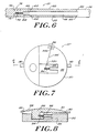
- FIGS. 5-6 show another embodiment of a pressure measurement device 10' coupled to an implantable CSF shunt system 50.
- the device 10' is coupled to the shunt system 50 fluid path via surgical tubing 52.
- the device 10' can monitor operation of a valve mechanism 54 in the shunt system by monitoring a pressure required for CSF to pass through the shunt system.
- the CSF pressure should be within desired levels to allow drainage of excess CSF while avoiding overdrainage conditions.
- the pressure measurement device 10' has a shunt end 56 adapted for coupling with the shunt system 50.
- the device 10' has an inner tube 58 axially secured in an outer tube 60 by spokes 62.
- a flexible member 64 extends from a first end 66 of the inner tube 58 with an amount of a fluid 68 trapped within the inner tube 58 and the flexible member 64.
- a position indicating member 70 is coupled to the flexible member 64 and axially expands and contracts as the fluid 68 volume changes.
- Position markings 72 are located on the position indicating member 70 and scale markings 74 are disposed about a circumference of the outer tube 60 to form a Vernier scale 76.
- An external imaging system is used to view the scale 76 and determine the location of the position indicating member 70 in the outer tube 60, and ultimately a physiological pressure.
- a disclosed pressure measurement device 10" is adapted for placement within a CSF fluid reservoir which forms a portion of a CSF shunt system (not shown).
- the device 10" has a rigid housing 80 with a first chamber 82 having an amount of a fluid 84 trapped therein, and a second chamber 86 having a first opening 88 and a second opening 90 to allow the passage of CSF.
- a flexible member 92 forms a portion of the first chamber 82 and expands and contracts in response to changes in volume of the fluid 84. Extending from an end of the flexible member 92 is a position indicating member 94.
- a needle 95 has a first end 95a coupled to the position indicating member 94 and a second end 95b proximate a series of scale markings 96.
- An intermediate portion 95c of the needle is secured to the housing at a pivot point 98 so that the second end 95b of the needles moves with respect to the scale markings 96 in response to movement of the flexible member 92.
- the device can include an access port 99 that is penetrable by a needle to allow sampling of CSF.
- a pressure measurement device is adapted for use with an external drainage system by a "Y" connector at the level of the patient's ventricles.
- the device can include one or more windows to enable a user to observe the position of the scale and position markings.
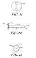
- FIGS. 9-15 show another disclosed embodiment of an implantable pressure indicator device 100.
- the device 100 includes a housing 102 comprising a first housing 102a coupled to a second housing 102b.
- a sealing member 104 which seals a predetermined amount of fluid within first housing 102a, is disposed at the interface of the first and second housings 102a,b.
- the device 100 also includes an elongate member 108 that is axially movable with respect to the first and second housings 102a,b.
- the elongate member 108 preferably includes a position indicating member 110 that forms a scale in conjunction with a rod 112, as described below, to indicate the relative position of the elongate member with respect to the rod 112.
- the rod 112 is disposed within the second housing 102b and is substantially co-axial with the elongate member 108.
- the first housing 102a has walls 116 extending from a closed end 118 to an open end 120 with an engaging mechanism 122 proximate the open end 120 for securing the first housing to the second housing 102b.
- the engaging mechanism 122 can be screw threads, an ultrasonic weld, an adhesive, or other means known to one of ordinary skill in the art.
- the engaging mechanism comprises male threads.
- the elongate member 108 includes a first end 108a and a second end 108b with a bore 114 formed in the first end 108a.
- the bore 114 can extend for the entire length of the elongate member 108 so that the elongate member is a hollow shaft, or the bore can extend for only a portion of the length of member 108.
- the bore 114 captures the rod 112 as the elongate member 108 moves in the housing over the pressure range of the device.
- An optional disk 124 can be affixed to the second end 108b of the elongate member.
- the disk preferably has a diameter that is slightly less than the inner diameter of the first housing 102a.
- the disk 124 is useful to prevent or restrict any non-axial movement of the elongate member 108 within the first housing 102a.
- the disk 124 also helps to seal the second end 108b of the elongate member where the elongate member is a hollow shaft.
- the disk 124 can include a blind hole into which the second end 108b of the elongate member can be affixed.
- the position indicating member 110 includes an axial opening 110a into which the first end 108a of the elongate member is inserted.
- the position indicating member 110 moves in concert with the elongate member 108 as elongate member 108 moves relative to the rod 112.
- the location of the position indicating member 110 in relation to the rod 112 indicates the differential between the external pressure and the pressure on the fluid 106 in the first housing 102a at the time of manufacture.
- the pressure differential manifests itself as the volume of the fluid in the first housing 102a, from which a physiological pressure is ultimately determined, as described below.
- the sealing member 104 includes an O-ring 104a and an elongated, integral sleeve 104b extending from the O-ring and terminating in an aperture 126.
- the O-ring 104a has an inner and outer diameter that substantially correspond to the inner and outer diameter of the open end 120 of the first housing. Upon mating the open end 120 of the first housing 102a to the second housing 102b, the O-ring 104a forms a seal at the interface of the first and second housings.
- the sleeve 104b has a tapered first portion 128 that extends from the O-ring and a second portion 130 that extends from the first portion.
- the second portion 130 has a substantially constant diameter and extends for a majority of the total length of the sealing member 104.
- a third portion 132 of the sleeve extends from the second portion 130 and tapers to a diameter that substantially matches a diameter of the elongate member 108 proximate the first end. The third portion 132 terminates in the aperture 126.
- the first end 108a of the elongate member extends through the aperture 126 in the sealing member.
- the elongate member 108 is secured to the sealing member about the aperture 126 to form a seal between the sealing member 104 and the elongate member 108.
- the sealing member 104 and the elongate member 108 cooperate to seal the fluid 106 in the first housing 102a.
- the second housing has an inlet end 138 and a mating end 136 with a shoulder 140 which increases the diameter of the mating end to receive the open end 120 of the first housing.
- the shoulder 140 compresses the O-ring 104a to form a seal at the interface of the first and second housings and trap the fluid 106 in the first housing 102a.
- An engagement mechanism 142 such as screw threads or other means, disposed on the mating end 136 proximate the shoulder 140 couples the first and second housings 102a,b together.
- the inlet end 138 of the second housing can include one or more passageways to communicate a pressure external to the device to the sealing member 104.
- the inlet end 138 includes a first passageway 146 and a second passageway 148.
- At least one scale marking 150 is located on the rod 112 and at least one position marking 152 is disposed on the position indicating member 110.
- the scale and position markings 150,152 form a scale to determine the location of the position indicating member 110 in the second housing 102b.
- the relative location of the position indicating member 110 indicates the volume of the fluid 106 in the first housing which is used to determine a physiological pressure, as discussed below.
- the scale and position markings 150,152 can be formed from various materials that are discernible, i.e., at least partially opaque, to an imaging system, such as an X-ray, fluoroscope, ultrasound, computed axial tomography (CAT) scan, magnetic resonance imaging (MRI) system, position emission (PET) or other such system. It is understood that the rod 112 and position indicating member 110 can also be formed from such materials and may include apertures or other negative surface features that can be seen on a compatible imaging system.
- an imaging system such as an X-ray, fluoroscope, ultrasound, computed axial tomography (CAT) scan, magnetic resonance imaging (MRI) system, position emission (PET) or other such system.
- CAT computed axial tomography
- MRI magnetic resonance imaging
- PET position emission
- the rod 112 and position indicating member 110 can also be formed from such materials and may include apertures or other negative surface features that can be seen on a compatible imaging system.
- Exemplary materials for the scale and position markings 22,38 include radiopaque metals such as titanium, titanium alloys, stainless steel, boron, tantalum, cobalt chrome alloys, gadolinium, barium, and radiopaque materials such as barium sulfate, doped methylmethacrylate, zirconium dioxide, alumina, hydroxyapatite, and processed bone.
- radiopaque metals such as titanium, titanium alloys, stainless steel, boron, tantalum, cobalt chrome alloys, gadolinium, barium, and radiopaque materials such as barium sulfate, doped methylmethacrylate, zirconium dioxide, alumina, hydroxyapatite, and processed bone.
- the scale and position markings 150,152 can be formed in many geometric configurations.
- the markings can be wires and/or apertures that are substantially coplanar, as well as circumferential markings or grooves. Such an arrangement can reduce parallax and allow the markings to be seen from a wide range of angles. It is understood that one of ordinary skill in the art can readily modify the particular embodiments disclosed herein.
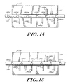
- FIGS. 14-15 show an illustrative embodiment of a scale formed from the scale and position markings 150,152.
- the scale markings 150 comprise apertures 150a-f formed in a metal (e.g., titanium) rod 112 and spaced at about 1.0 millimeter increments.
- the position markings 152 include a single metal (e.g., titanium) wire 152e above the rod 112 and four metal (e.g., titanium) wires 152a-d below the rod. It is understood that the terms “above” and “below” are relative terms only and correspond to the exemplary embodiment shown.
- the single metal wire 152e is inserted into a hole in the position indicating 110 member with an interference fit.
- the four metal wires 152a-d are similarly inserted into an opposite side of the position indicating member.
- the four wires 152a-d are spaced approximately at 1.2 millimeter intervals along the length of the position indicating member 110, with the wire 152d nearest the inlet end of the second housing being about 0.4 millimeter from an end 153 of the position indicating member 110.
- the single wire 152e is about 1.2 millimeters from the end 153 of the position indicating member. Thus, the single wire 152e is not directly aligned with any of the four wires 152a-d.
- FIG. 14 shows a respective aperture 150b aligned with the single wire 152b.
- the location of the position indicating member 110 with respect to the rod 112 is readily determined. From this positional arrangement, the fluid 28 volume and corresponding external pressure are known. As discussed below, the physiological pressure proximate a site of implantation can then be determined in relation to ambient pressure.
- FIG. 15 shows the single wire 152e not aligned with an aperture 150. Instead, it is disposed between apertures 150c and 150b. Thus, the single wire 152e does not provide the exact location of the position indicating member 110 with respect to the rod 112. However, the third wire 152d is aligned with an aperture 150d. Since, in the exemplary embodiment, the spacing of the apertures 150 is known to be 1.0 millimeter and the spacing of the four wires 152a-d is known to be 1.2 millimeters, the exact location of the position indicating member 110 in relation to the rod 112 can be readily determined. From the location of the position indicating member 110 with respect to the rod 112, a physiological pressure can be established, as discussed below.
- the shape and dimensions of the various components described above can vary depending upon the intended application, the anticipated site of implantation, and the expected pressure ranges.
- the components are sized to allow free movement of the elongate member within the first and second housings.
- the sealing member can flex to accommodate movement of the elongate member and/or it can elastically deform as the fluid in the first housing expands. Moreover, movement of the elongate member in response to pressure changes need not be linear, but it should be predictable.
- the housing 102 can be of any shape that allows sufficient axial movement of the elongate member 108 over a pressure range of the device.
- the housing can be formed in any suitable shape, including annular, cylindrical, ovular, and rectangular. In a preferred embodiment, the housing has a cylindrical shape.
- the first housing 102a is about 18.50 millimeters in length and has inner and outer diameters of about 4.00 and 5.00 millimeters, respectively.
- the elongate member 108 is about 23.5 millimeters in length with a 1.13 millimeter outer diameter and 0.80 millimeter bore diameter.
- the O-ring 104a of the sealing member has inner and outer diameters that correspond to the inner and outer diameters of the first housing and has an overall length of about 20.00 millimeters.
- the sleeve 104b second portion has a diameter of about 1.25 millimeters tapering to the aperture 126 which has a diameter of about 1.13 millimeters to match the outer diameter of the elongate member 108.
- the thickness of the sleeve 104b is less than about 0.30 millimeter.
- the position indicating member 110 has a length of about 4.40 millimeters and a diameter of about 3.80 millimeters.
- the holes for the wires 152 are about 0.40 millimeters in diameter and about 1.20 millimeters in depth.
- the rod 112 is about 20.50 millimeters in length and 0.60 millimeter in diameter.
- the second housing 102b has an inner diameter of about 4.00 millimeters and outer diameters of about 5.00 millimeters at the inlet end and about 7.00 millimeters at the mating end.
- the fluid 106 in the first housing 102a expands and contracts until the pressure on the fluid 106 and the external pressure are substantially equal. This causes the elongate member 108 and position indicating member 110 to move with respect to the rod 112.
- the location of the position indicating member 110 is representative of a volume of the fluid 106 in the first housing 102a. From the volume of the fluid 106, the corresponding external pressure is determined. Ambient pressure is established and subtracted from the external pressure to determine a pressure at the site of implantation.
- FIG. 9 shows the maximum pressure measurable by the disclosed device.
- the pressure differential on the opposite sides of the sealing member 104 causes the second end 108b of the elongate member move to abut the sealed end 118 of the first housing.
- FIG. 10 shows the minimum pressure that is measurable by the disclosed device. As the pressure differential decreases, the fluid expands thereby moving the elongate member in the direction of the second housing 102b.
- an image of the device must be obtained.
- This image can be obtained using a suitable imaging system, as noted above. Examples of such systems include X-ray, fluoroscope, ultrasound, computer axial tomography (CAT) scan, and magnetic resonance imaging (MRI) systems and position emission (PET) scans.
- the image indicates the relative position of the position indicating member 110 with respect to the rod 112. That is, the imaging system reveals the location of the position indicating member 110 in relation to the scale and position markings 150,152. The location of the position indicating member 110 is compared with a known initial position of the position indicating member to determine whether the external pressure has increased or decreased.
- the pressure measurement device of the present invention has a range of measurable pressures that is appropriate for a particular application.
- intracranial pressure is generally measured in millimeters of water (mm H 2 O) with a typical range from about 0 to 200 mm H 2 O above ambient pressure.
- Pathological levels of intracranial pressure above about 250 mm H 2 O are generally considered dangerous.
- a pressure measurement device for implantation within the cranium of a patient should therefore be able to measure pressures within this range, preferably with a resolution of about 10 to 20 mm H 2 O or better.
- an implanted device it is desirable for an implanted device to be able to measure intracranial pressure at low ambient pressures in conjunction with a nominal intracranial pressure and at high ambient pressures with elevated intracranial pressures.
- a typical atmospheric pressure is about 10400 mm H 2 O (one standard atmosphere is about 10332 mm H 2 O).
- the device is assembled at an ambient pressure at about 10400 mm H 2 O and has a measurable pressure range from about 10250 to about 10850 mm H 2 O.
- the device can measure a pressure from about 150 mm H 2 O below to about 450 mm H 2 O above an atmospheric pressure of about 10400 mm H 2 O.
- the resolution of the device is about 10 mm H 2 O in the range from 10250 mm H 2 O to about 10850 mm H 2 O where the initial pressure on the fluid in the first housing is about 10400 mm H 2 O.
- movement of the elongate member by about 10 millimeters is detectable in the exemplary embodiment.
- a movement of about 1 millimeter results from about a 50 mm H 2 O change in pressure differential.
- the disclosed device 100 can be adapted for implantation by itself or for connection to a shunt system as described in conjunction with the embodiment of FIG. 1.
- the first passageway 146 can be covered with a membrane and the second passageway blocked or sealed.
- surgical tubing extending from the first passageway can communicate with a sealed membrane to allow the device to measure pressure proximate the membrane.
- the housing can be implanted under the scalp and the membrane be located within the cranium.
- tubing can coupled to the first and second passageways 146,148.
- the first passageway can serve as an inlet and the second passageway as an outlet for fluid through the shunt system.
- the pressure measurement device of the present invention can readily be adapted for other applications as well.
- the device can be incorporated into a vascular aneurysm repair sheath to measure blood pressure.
- a pressure measurement device in placed within the gastrointestinal tract to measure physiological pressures proximate the device. It is understood that other such applications will be readily apparent to one of ordinary skill in the art.
- the components of the device can be made from a variety of biocompatible materials having the properties required for the particular component.
- the first housing is formed from a suitably rigid bioimplantable material.
- the first housing must be sufficiently rigid so that the housing does not deform in the presence of a physiological pressure to be measured.
- Exemplary materials include polyethylene.
- a preferred material is polyethersulphone.
- the disk 124 can be made from a variety of materials suitable for implantation within the body. Exemplary materials include polymethymethacrylate, polyurethane, or a medical grade silicone. A preferred material is a high-durometer silicone.
- the sealing member 104 is formed from a bioimplantable material of sufficient flexibility to allow movement of the elongate member 108 with minimal resistance.
- the material must be flexible and can also be elastic. Preferably, the material can withstand pressures beyond the range measurable by the device, such as those pressures experienced at high altitudes or at depths below sea level.
- the sealing member material should not adhere to itself or other device components. Exemplary materials include polymers such as silicones and polyurethanes.
- a preferred material for the sealing member is a medical grade silicone impregnated with polytetrafluoroethylene (PTFE).
- the rod 112 can be formed from suitable rigid, bioimplantable materials in which markings can be formed that are discernible on an imaging system, such as X-ray, fluoroscope, or magnetic resonance imaging system.
- suitable materials include polymers and metals such as titanium, titanium alloys, stainless steel and polymers.
- a preferred material is titanium.
- the fluid 106 sealed in the first housing 102a can any fluid that adequately expands and contracts in response to pressure. Suitable fluids includes air, nitrogen, and noble gases such as argon. Chlorofluorocarbons (CFCs) can also be used in conjunction with an infusion pump. A preferred fluid is air.
Landscapes
- Health & Medical Sciences (AREA)
- Life Sciences & Earth Sciences (AREA)
- Molecular Biology (AREA)
- Engineering & Computer Science (AREA)
- Physics & Mathematics (AREA)
- Animal Behavior & Ethology (AREA)
- Biophysics (AREA)
- Pathology (AREA)
- Surgery (AREA)
- Biomedical Technology (AREA)
- Heart & Thoracic Surgery (AREA)
- Medical Informatics (AREA)
- Veterinary Medicine (AREA)
- Public Health (AREA)
- General Health & Medical Sciences (AREA)
- Hematology (AREA)
- Cardiology (AREA)
- Physiology (AREA)
- Vascular Medicine (AREA)
- Neurosurgery (AREA)
- Measuring And Recording Apparatus For Diagnosis (AREA)
- Measuring Fluid Pressure (AREA)
- Measurement Of Length, Angles, Or The Like Using Electric Or Magnetic Means (AREA)
- Media Introduction/Drainage Providing Device (AREA)
- External Artificial Organs (AREA)
- Measuring Pulse, Heart Rate, Blood Pressure Or Blood Flow (AREA)
Claims (12)
- Extern abbildbare bioimplantierbare Druckmessvorrichtung (10), umfassend:dadurch gekennzeichnet, daßein Gehäuse (14) mit einem Durchgang (16), einer Kammer (18), wobei der Durchgang (16) dazu dient, einen außerhalb der Vorrichtung existierenden Druck in die Kammer hinein weiterzugeben;ein in der Kammer (18) angeordnetes flexibles Glied (26), welches ein Gas (28) enthält; undein mit dem flexiblen Glied (26) gekoppeltes Positionsanzeigeglied (36), wobei das Positionsanzeigeglied (36) in dem Durchgang (16) dergestalt bewegt werden kann, daß die relative Position des Positionsanzeigegliedes (36) in Bezug auf das Gehäuse (14) den Druck anzeigt, der außerhalb der Vorrichtung existiert;
das Gehäuse (14) wenigstens eine Skalenmarkierung (22) aufweist,
das Positionsanzeigeglied (36) wenigstens eine Positionsmarkierung (38) umfaßt, dergestalt, daß die relative Position des Positionsanzeigegliedes (36) in Bezug auf das Gehäuse (14) extern abbildbar ist. - Vorrichtung nach Anspruch 1, dadurch gekennzeichnet, daß
die wenigstens eine Positionsmarkierung (38) und die wenigstens eine Skalenmarkierung (22) wenigstens teilweise undurchlässig und durch ein Abbildungssystem erkennbar sind. - Vorrichtung nach Anspruch 1, dadurch gekennzeichnet, daß
die wenigstens eine Skalenmarkierung (22) eine Vielzahl von Markierungen von unterschiedlicher Undurchlässigkeit und mit unterschiedlichen Graden der Erkerinbarkeit durch ein externes Abbildungssystem enthält. - Vorrichtung nach Anspruch 1, dadurch gekennzeichnet, daß
die wenigstens eine Positionsmarkierung (38) und die wenigstens eine Skalenmarkierung (22) eine Noniusskala bilden. - Vorrichtung nach Anspruch 1, dadurch gekennzeichnet, daß
die wenigstens eine Positionsmarkierung (38) und die wenigstens eine Skalenmarkierung (22) im Wesentlichen planar sind. - Vorrichtung nach Anspruch 1, ferner umfassend
ein Abdeckungselement (12), das in der Lage ist, die Vorrichtung (10) von Körperfluiden zu isolieren. - Vorrichtung nach Anspruch 6, ferner umfassend
ein Fluid (13), das durch das Abdeckungselement (12) eingeschlossen ist. - Vorrichtung nach Anspruch 1, dadurch gekennzeichnet, daß
die Vorrichtung (10) dazu geeignet ist, daß sie an ein Abzweigventilsystem (50) angeschlossen werden kann. - Vorrichtung nach Anspruch 1, dadurch gekennzeichnet, daß
das flexible Glied (26) einen Balgabschnitt (34) enthält. - Vorrichtung nach Anspruch 1, dadurch gekennzeichnet, daß
es sich bei dem Gas (28) um Luft, Sauerstoff und/oder Stickstoff handelt. - Vorrichtung nach Anspruch 1, dadurch gekennzeichnet, daß
die wenigstens eine Positionsmarkierung (38) und die wenigstens eine Skalenmarkierung (22) aus einem strahlungsundurchlässigen Material hergestellt sind. - Vorrichtung nach Anspruch 1, dadurch gekennzeichnet, daß
die wenigstens eine Positionsmarkierung (38) eine Nadel umfaßt, die drehbar mit dem flexiblen Glied (26) verbunden ist.
Priority Applications (1)
| Application Number | Priority Date | Filing Date | Title |
|---|---|---|---|
| EP05075821A EP1552784B1 (de) | 1997-09-30 | 1998-09-29 | Implantierbarer Druckanzeiger |
Applications Claiming Priority (2)
| Application Number | Priority Date | Filing Date | Title |
|---|---|---|---|
| US08/940,667 US5935084A (en) | 1997-09-30 | 1997-09-30 | Inflatable pressure indicator |
| US940667 | 1997-09-30 |
Related Child Applications (1)
| Application Number | Title | Priority Date | Filing Date |
|---|---|---|---|
| EP05075821A Division EP1552784B1 (de) | 1997-09-30 | 1998-09-29 | Implantierbarer Druckanzeiger |
Publications (3)
| Publication Number | Publication Date |
|---|---|
| EP0904728A2 EP0904728A2 (de) | 1999-03-31 |
| EP0904728A3 EP0904728A3 (de) | 2000-03-29 |
| EP0904728B1 true EP0904728B1 (de) | 2005-11-23 |
Family
ID=25475228
Family Applications (2)
| Application Number | Title | Priority Date | Filing Date |
|---|---|---|---|
| EP98307901A Expired - Lifetime EP0904728B1 (de) | 1997-09-30 | 1998-09-29 | Implantierbarer Druckanzeiger |
| EP05075821A Expired - Lifetime EP1552784B1 (de) | 1997-09-30 | 1998-09-29 | Implantierbarer Druckanzeiger |
Family Applications After (1)
| Application Number | Title | Priority Date | Filing Date |
|---|---|---|---|
| EP05075821A Expired - Lifetime EP1552784B1 (de) | 1997-09-30 | 1998-09-29 | Implantierbarer Druckanzeiger |
Country Status (4)
| Country | Link |
|---|---|
| US (1) | US5935084A (de) |
| EP (2) | EP0904728B1 (de) |
| JP (2) | JP4553999B2 (de) |
| DE (2) | DE69832445T2 (de) |
Cited By (1)
| Publication number | Priority date | Publication date | Assignee | Title |
|---|---|---|---|---|
| US8088091B2 (en) | 2009-03-09 | 2012-01-03 | New Jersey Institute Of Technology | No clog shunt using a compact fluid drag path |
Families Citing this family (85)
| Publication number | Priority date | Publication date | Assignee | Title |
|---|---|---|---|---|
| NL1014566C2 (nl) * | 2000-03-06 | 2001-10-04 | Beleggings En Exploitatie Mij | Implanteerbare drukbewakingsinrichting. |
| US6394965B1 (en) * | 2000-08-15 | 2002-05-28 | Carbon Medical Technologies, Inc. | Tissue marking using biocompatible microparticles |
| US6543294B2 (en) * | 2000-12-15 | 2003-04-08 | Bell Helicopter Textron Inc. | Sealed pressure indicator |
| US6890303B2 (en) * | 2001-05-31 | 2005-05-10 | Matthew Joseph Fitz | Implantable device for monitoring aneurysm sac parameters |
| WO2002098274A2 (en) * | 2001-06-05 | 2002-12-12 | Apex Medical, Inc. | Distributed port pressure monitor |
| US6682490B2 (en) * | 2001-12-03 | 2004-01-27 | The Cleveland Clinic Foundation | Apparatus and method for monitoring a condition inside a body cavity |
| US7699059B2 (en) * | 2002-01-22 | 2010-04-20 | Cardiomems, Inc. | Implantable wireless sensor |
| US6855115B2 (en) * | 2002-01-22 | 2005-02-15 | Cardiomems, Inc. | Implantable wireless sensor for pressure measurement within the heart |
| US9694166B2 (en) | 2002-03-26 | 2017-07-04 | Medtronics Ps Medical, Inc. | Method of draining cerebrospinal fluid |
| AUPS255902A0 (en) * | 2002-05-24 | 2002-06-13 | Ultimate Medical Pty. Ltd. | Device and method for pressure indication |
| US7147604B1 (en) | 2002-08-07 | 2006-12-12 | Cardiomems, Inc. | High Q factor sensor |
| EP1581102A4 (de) | 2002-12-11 | 2006-12-20 | Proteus Biomedical Inc | Verfahren und system zur überwachung und behandlung von hämodynamischen parametern |
| US7204798B2 (en) * | 2003-01-24 | 2007-04-17 | Proteus Biomedical, Inc. | Methods and systems for measuring cardiac parameters |
| JP4528766B2 (ja) * | 2003-01-24 | 2010-08-18 | プロテウス バイオメディカル インコーポレイテッド | 遠隔血行力学的モニタリングのためのシステム |
| US7200439B2 (en) | 2003-01-24 | 2007-04-03 | Proteus Biomedical, Inc. | Method and apparatus for enhancing cardiac pacing |
| US7318813B2 (en) * | 2003-06-26 | 2008-01-15 | Codman & Shurtleff, Inc. | Self adjusting hydrocephalus valve |
| US20050043670A1 (en) * | 2003-08-22 | 2005-02-24 | Codman & Shurtleff, Inc. | Intra-ventricular pressure sensing catheter |
| US8026729B2 (en) | 2003-09-16 | 2011-09-27 | Cardiomems, Inc. | System and apparatus for in-vivo assessment of relative position of an implant |
| US7245117B1 (en) | 2004-11-01 | 2007-07-17 | Cardiomems, Inc. | Communicating with implanted wireless sensor |
| AU2004274005A1 (en) * | 2003-09-16 | 2005-03-31 | Cardiomems, Inc. | Implantable wireless sensor |
| US7214189B2 (en) * | 2004-09-02 | 2007-05-08 | Proteus Biomedical, Inc. | Methods and apparatus for tissue activation and monitoring |
| WO2006105474A2 (en) | 2005-03-31 | 2006-10-05 | Proteus Biomedical, Inc. | Automated optimization of multi-electrode pacing for cardiac resynchronization |
| US7662653B2 (en) * | 2005-02-10 | 2010-02-16 | Cardiomems, Inc. | Method of manufacturing a hermetic chamber with electrical feedthroughs |
| US7647836B2 (en) * | 2005-02-10 | 2010-01-19 | Cardiomems, Inc. | Hermetic chamber with electrical feedthroughs |
| US8021307B2 (en) | 2005-03-03 | 2011-09-20 | Cardiomems, Inc. | Apparatus and method for sensor deployment and fixation |
| US8118749B2 (en) * | 2005-03-03 | 2012-02-21 | Cardiomems, Inc. | Apparatus and method for sensor deployment and fixation |
| CA2613241A1 (en) | 2005-06-21 | 2007-01-04 | Cardiomems, Inc. | Method of manufacturing implantable wireless sensor for in vivo pressure measurement |
| US7621036B2 (en) * | 2005-06-21 | 2009-11-24 | Cardiomems, Inc. | Method of manufacturing implantable wireless sensor for in vivo pressure measurement |
| US20070038171A1 (en) * | 2005-07-25 | 2007-02-15 | Mayer Peter L | Shunt system |
| JP4728064B2 (ja) * | 2005-08-10 | 2011-07-20 | 川澄化学工業株式会社 | 生体内圧測定装置 |
| WO2007021804A2 (en) | 2005-08-12 | 2007-02-22 | Proteus Biomedical, Inc. | Evaluation of depolarization wave conduction velocity |
| CA2645770C (en) | 2006-03-14 | 2016-01-26 | Cardiomems, Inc. | Communicating with an implanted wireless sensor |
| ES2284416B1 (es) * | 2007-05-21 | 2009-02-16 | Ahmed Galal Ahmed | "dispositivo para el control de la presion intraocular". |
| PT3269417T (pt) | 2007-06-20 | 2025-11-05 | Medical Components Inc | Dispositivo de acesso implantável com indicações moldadas e/ou radiopacas |
| ES2650800T5 (en) | 2007-07-19 | 2025-05-05 | Medical Components Inc | Venous access port assembly with x-ray discernable indicia |
| US9610432B2 (en) | 2007-07-19 | 2017-04-04 | Innovative Medical Devices, Llc | Venous access port assembly with X-ray discernable indicia |
| WO2009131749A2 (en) | 2008-02-28 | 2009-10-29 | Proteus Biomedical, Inc. | Integrated circuit implementation and fault control system, device, and method |
| WO2009132396A1 (en) * | 2008-05-02 | 2009-11-05 | Commonwealth Scientific And Industrial Research Organisation | Method and apparatus for determining the pressure of a fluid |
| GB0903654D0 (en) | 2009-03-03 | 2009-04-15 | Laryngeal Mask Company The Ltd | Artificial airway device |
| JP2012525206A (ja) * | 2009-04-29 | 2012-10-22 | プロテウス バイオメディカル インコーポレイテッド | 移植可能なデバイスのためのリード線のための方法および装置 |
| KR20120070559A (ko) | 2009-07-06 | 2012-06-29 | 우메데이스 리미티드 | 인공 기도 |
| JP5730872B2 (ja) | 2009-07-23 | 2015-06-10 | プロテウス デジタル ヘルス, インコーポレイテッド | 固体薄膜コンデンサ |
| EP3534128A3 (de) | 2009-08-13 | 2020-01-08 | Teleflex Life Sciences Unlimited Company | Druckanzeiger |
| DE102009060533B4 (de) | 2009-12-23 | 2019-07-11 | Christoph Miethke Gmbh & Co Kg | Implantierbares Shuntsystem |
| US9475709B2 (en) | 2010-08-25 | 2016-10-25 | Lockheed Martin Corporation | Perforated graphene deionization or desalination |
| ES2695043T3 (es) | 2010-10-15 | 2018-12-28 | Teleflex Life Sciences Unlimited Company | Dispositivo de vía respiratoria artificial |
| US8718770B2 (en) | 2010-10-21 | 2014-05-06 | Medtronic, Inc. | Capture threshold measurement for selection of pacing vector |
| CA2817482C (en) | 2010-11-12 | 2018-10-30 | Wolfe Tory Medical, Inc. | Atomizer for nasal therapy |
| US9717420B2 (en) * | 2010-12-20 | 2017-08-01 | Empire Technology Development Llc | Implantable apparatus for facilitating imaging-based diagnoses |
| JP6242687B2 (ja) | 2011-02-02 | 2017-12-06 | ウメダス、リミテッドUmedaes Limited | 改良型人工気道 |
| US8776606B2 (en) | 2011-03-06 | 2014-07-15 | Alexander H. Slocum | Unrolling tube pressure sensor |
| US8397577B2 (en) | 2011-03-06 | 2013-03-19 | Alexander Henry Slocum, Sr. | Rolling diaphragm pressure sensor |
| US8881594B2 (en) | 2011-03-06 | 2014-11-11 | Alexander Henry Slocum | Tapered spiral bellows pressure sensor |
| US8355784B2 (en) | 2011-05-13 | 2013-01-15 | Medtronic, Inc. | Dynamic representation of multipolar leads in a programmer interface |
| WO2013055329A1 (en) * | 2011-10-12 | 2013-04-18 | Washington University | Implantable pressure indicator with external interrogation |
| GB201120628D0 (en) | 2011-11-30 | 2012-01-11 | Laryngeal Mask Company The Ltd | Endoscopy device |
| US10653824B2 (en) | 2012-05-25 | 2020-05-19 | Lockheed Martin Corporation | Two-dimensional materials and uses thereof |
| US9744617B2 (en) | 2014-01-31 | 2017-08-29 | Lockheed Martin Corporation | Methods for perforating multi-layer graphene through ion bombardment |
| US9834809B2 (en) | 2014-02-28 | 2017-12-05 | Lockheed Martin Corporation | Syringe for obtaining nano-sized materials for selective assays and related methods of use |
| US9844757B2 (en) | 2014-03-12 | 2017-12-19 | Lockheed Martin Corporation | Separation membranes formed from perforated graphene and methods for use thereof |
| US10376845B2 (en) | 2016-04-14 | 2019-08-13 | Lockheed Martin Corporation | Membranes with tunable selectivity |
| US9610546B2 (en) | 2014-03-12 | 2017-04-04 | Lockheed Martin Corporation | Separation membranes formed from perforated graphene and methods for use thereof |
| TW201504140A (zh) | 2013-03-12 | 2015-02-01 | Lockheed Corp | 形成具有均勻孔尺寸之多孔石墨烯之方法 |
| US9649481B2 (en) * | 2013-03-14 | 2017-05-16 | Siddharth Sadanand | Shunt flow monitor |
| EP2968730B1 (de) | 2013-03-15 | 2019-01-09 | Bitol Designs, LLC | Okklusionsresistenter katheter und verfahren zur verwendung |
| US9572918B2 (en) | 2013-06-21 | 2017-02-21 | Lockheed Martin Corporation | Graphene-based filter for isolating a substance from blood |
| GB201314631D0 (en) | 2013-08-15 | 2013-10-02 | Teleflex Life Sciences | Endoscopy device |
| CN106029596A (zh) | 2014-01-31 | 2016-10-12 | 洛克希德马丁公司 | 采用多孔非牺牲性支撑层的二维材料形成复合结构的方法 |
| CN105940479A (zh) | 2014-01-31 | 2016-09-14 | 洛克希德马丁公司 | 使用宽离子场穿孔二维材料 |
| JP2017534311A (ja) | 2014-09-02 | 2017-11-24 | ロッキード・マーチン・コーポレーション | 二次元膜材料をベースとする血液透析膜および血液濾過膜、ならびにそれを用いた方法 |
| US9974932B2 (en) | 2014-09-05 | 2018-05-22 | University Of Southern California | Method and sensor for detecting catheter obstruction |
| US11478195B2 (en) | 2015-01-14 | 2022-10-25 | University Of Southern California | Multi-sensor platform for diagnosing catheter status |
| US10226193B2 (en) | 2015-03-31 | 2019-03-12 | Medtronic Ps Medical, Inc. | Wireless pressure measurement and monitoring for shunts |
| JP2018528144A (ja) | 2015-08-05 | 2018-09-27 | ロッキード・マーチン・コーポレーション | グラフェン系材料の穿孔可能なシート |
| WO2017023377A1 (en) | 2015-08-06 | 2017-02-09 | Lockheed Martin Corporation | Nanoparticle modification and perforation of graphene |
| US10667745B2 (en) | 2015-08-12 | 2020-06-02 | Clemson University Research Foundation | Radiographic discernable sensors and orthopedic applications for same |
| EP3442739A4 (de) | 2016-04-14 | 2020-03-04 | Lockheed Martin Corporation | Verfahren zur behandlung von graphenfolien für grossflächigen transfer mittels free-float-verfahren |
| KR20180133430A (ko) | 2016-04-14 | 2018-12-14 | 록히드 마틴 코포레이션 | 결함 형성 또는 힐링의 인 시츄 모니터링 및 제어를 위한 방법 |
| EP3442697A4 (de) | 2016-04-14 | 2020-03-18 | Lockheed Martin Corporation | Selektive grenzflächenminderung von graphendefekten |
| WO2017180134A1 (en) | 2016-04-14 | 2017-10-19 | Lockheed Martin Corporation | Methods for in vivo and in vitro use of graphene and other two-dimensional materials |
| EP3442786A4 (de) | 2016-04-14 | 2020-03-18 | Lockheed Martin Corporation | Zweidimensionale membranstrukturen mit strömungskanälen |
| GB201611935D0 (en) * | 2016-07-08 | 2016-08-24 | Demetriou Vias | Apparatus for measuring pressure within a stunt |
| AU201714823S (en) | 2017-02-27 | 2017-10-12 | Teleflex Life Sciences Unlimited Co | Laryngeal mask airway device |
| DE102018132372A1 (de) * | 2018-12-15 | 2020-06-18 | Tricumed Medizintechnik Gmbh | Vorrichtung zur Katheterüberwachung |
| CN111780914B (zh) * | 2020-06-12 | 2025-04-29 | 广西浩天峰科技有限公司 | 一种双向伸缩膨胀的预警式波纹管 |
Family Cites Families (18)
| Publication number | Priority date | Publication date | Assignee | Title |
|---|---|---|---|---|
| US3625199A (en) * | 1969-11-06 | 1971-12-07 | Fairchild Hiller Corp | Implantable pressure indicator |
| JPS50118770A (de) * | 1974-02-28 | 1975-09-17 | ||
| JPS51107690A (ja) * | 1975-03-17 | 1976-09-24 | Kunihiko Osaka | Iryoyozugainaiatsuryokukei |
| FR2325351A1 (fr) * | 1975-05-23 | 1977-04-22 | Pertuiset Bernard | Mano capteur emetteur de pression ventriculaire cerebrale a scalp ferme |
| US4206762A (en) * | 1976-06-21 | 1980-06-10 | Cosman Eric R | Telemetric differential pressure sensing method |
| IT1071114B (it) * | 1976-07-02 | 1985-04-02 | Alinari Carlo | Trasduttore di pressione per fluidi e strumento per la misura di pressioni incorporante tale trasduttore |
| JPS54133884U (de) * | 1978-03-08 | 1979-09-17 | ||
| US4481952A (en) * | 1978-03-22 | 1984-11-13 | Jerzy Pawelec | Device for the study of the alimentary canal |
| US4231376A (en) * | 1978-08-07 | 1980-11-04 | Hittman Corporation | Pressure sensor |
| US4627443A (en) * | 1980-10-29 | 1986-12-09 | The Johns Hopkins University | X-ray readable implantable pressure sensor |
| JPS60134003U (ja) * | 1984-02-18 | 1985-09-06 | 三菱自動車工業株式会社 | タイヤ空気圧表示装置 |
| US4589287A (en) * | 1984-09-17 | 1986-05-20 | American Hospital Supply Corporation | Strain gauge for medical pressure measurements |
| US4723556A (en) * | 1986-04-14 | 1988-02-09 | Cordis Corporation | Intracranial ventricular catheter assembly |
| JPH0346729Y2 (de) * | 1987-04-06 | 1991-10-03 | ||
| JP2712317B2 (ja) * | 1988-06-30 | 1998-02-10 | 株式会社島津製作所 | 温度測定装置 |
| US5325865A (en) * | 1990-02-26 | 1994-07-05 | Baxter International, Inc. | Intracranial pressure monitoring system |
| US5257630A (en) * | 1992-05-15 | 1993-11-02 | Thermometrics, Inc. | Pressure sensing probe with calibration capability |
| JPH0743235A (ja) * | 1993-07-28 | 1995-02-14 | Mitsubishi Denki Bill Techno Service Kk | 簡易型記録計付圧力計 |
-
1997
- 1997-09-30 US US08/940,667 patent/US5935084A/en not_active Expired - Lifetime
-
1998
- 1998-09-29 EP EP98307901A patent/EP0904728B1/de not_active Expired - Lifetime
- 1998-09-29 EP EP05075821A patent/EP1552784B1/de not_active Expired - Lifetime
- 1998-09-29 DE DE69832445T patent/DE69832445T2/de not_active Expired - Lifetime
- 1998-09-29 DE DE69839232T patent/DE69839232T2/de not_active Expired - Lifetime
- 1998-09-29 JP JP29014398A patent/JP4553999B2/ja not_active Expired - Fee Related
-
2008
- 2008-07-04 JP JP2008175434A patent/JP4307512B2/ja not_active Expired - Fee Related
Cited By (1)
| Publication number | Priority date | Publication date | Assignee | Title |
|---|---|---|---|---|
| US8088091B2 (en) | 2009-03-09 | 2012-01-03 | New Jersey Institute Of Technology | No clog shunt using a compact fluid drag path |
Also Published As
| Publication number | Publication date |
|---|---|
| JP4553999B2 (ja) | 2010-09-29 |
| DE69832445D1 (de) | 2005-12-29 |
| JP2008249728A (ja) | 2008-10-16 |
| EP0904728A2 (de) | 1999-03-31 |
| DE69839232D1 (de) | 2008-04-17 |
| JP4307512B2 (ja) | 2009-08-05 |
| EP1552784A1 (de) | 2005-07-13 |
| EP1552784B1 (de) | 2008-03-05 |
| JPH11218455A (ja) | 1999-08-10 |
| DE69839232T2 (de) | 2009-03-12 |
| EP0904728A3 (de) | 2000-03-29 |
| US5935084A (en) | 1999-08-10 |
| DE69832445T2 (de) | 2006-07-27 |
Similar Documents
| Publication | Publication Date | Title |
|---|---|---|
| EP0904728B1 (de) | Implantierbarer Druckanzeiger | |
| JP5595990B2 (ja) | 感圧器具 | |
| US8353857B2 (en) | Implantable medical device having pressure sensors for diagnosing the performance of an implanted medical device | |
| JP2972251B2 (ja) | 体内圧力の長期測定装置 | |
| US4172449A (en) | Body fluid pressure monitor | |
| JP4744827B2 (ja) | 圧力センサ装置、脳室カテーテル、及び、脳室内圧力センサ装置を製造するための方法 | |
| EP2432544B1 (de) | Passiver Flüssigkeitsflussregler | |
| US6537232B1 (en) | Intracranial pressure monitoring device and method for use in MR-guided drug delivery | |
| EP1985229A2 (de) | System für Drainage des Liquors aus einer Flüssigkeitshöhle des Gehirns- oder Rückenmarks | |
| US7776003B2 (en) | Multimodal catheter for focal brain monitoring and ventriculostomy | |
| US8457733B2 (en) | Monitoring and controlling hydrocephalus | |
| US20040068201A1 (en) | Systems and methods for flow detection and measurement in CSF shunts | |
| WO2003096903A1 (en) | Sensor unit and method for sensing a blood related parameter and system including such a sensor unit | |
| US20050020962A1 (en) | Diagnostic algorithms for a csf physiologic controller | |
| US20080281210A1 (en) | Arterial pressure sensing device | |
| JP5301210B2 (ja) | 支えられたセンサ組立体 | |
| US4627443A (en) | X-ray readable implantable pressure sensor | |
| EP3829425B1 (de) | Drucksensoreinrichtung für medizinische in vivo anwendung, und herstellungsverfahren für eine solche einrichtung | |
| US20250090819A1 (en) | Devices and methods for shunt evaluation | |
| EP3481487B1 (de) | Vorrichtung zur messung des drucks in einem nebenschluss | |
| DE102024000814A1 (de) | System zur Bestimmung und Überwachung von kardiologischen Parametern und Verfahren | |
| Hittman et al. | Pressure sensor apparatus | |
| Ohta et al. | Detection of the site of VP shunt malfunction using a telemetric IVP sensor | |
| Ohta et al. | Using a Telemetric IVP Sensor |
Legal Events
| Date | Code | Title | Description |
|---|---|---|---|
| PUAI | Public reference made under article 153(3) epc to a published international application that has entered the european phase |
Free format text: ORIGINAL CODE: 0009012 |
|
| AK | Designated contracting states |
Kind code of ref document: A2 Designated state(s): DE FR GB |
|
| AX | Request for extension of the european patent |
Free format text: AL;LT;LV;MK;RO;SI |
|
| PUAL | Search report despatched |
Free format text: ORIGINAL CODE: 0009013 |
|
| AK | Designated contracting states |
Kind code of ref document: A3 Designated state(s): AT BE CH CY DE DK ES FI FR GB GR IE IT LI LU MC NL PT SE |
|
| AX | Request for extension of the european patent |
Free format text: AL;LT;LV;MK;RO;SI |
|
| 17P | Request for examination filed |
Effective date: 20000904 |
|
| AKX | Designation fees paid |
Free format text: DE FR GB |
|
| RAP1 | Party data changed (applicant data changed or rights of an application transferred) |
Owner name: DEPUY PRODUCTS, INC. |
|
| RAP1 | Party data changed (applicant data changed or rights of an application transferred) |
Owner name: DEPUY PRODUCTS, INC. |
|
| 17Q | First examination report despatched |
Effective date: 20030722 |
|
| GRAP | Despatch of communication of intention to grant a patent |
Free format text: ORIGINAL CODE: EPIDOSNIGR1 |
|
| GRAS | Grant fee paid |
Free format text: ORIGINAL CODE: EPIDOSNIGR3 |
|
| GRAA | (expected) grant |
Free format text: ORIGINAL CODE: 0009210 |
|
| AK | Designated contracting states |
Kind code of ref document: B1 Designated state(s): DE FR GB |
|
| REG | Reference to a national code |
Ref country code: GB Ref legal event code: FG4D |
|
| REF | Corresponds to: |
Ref document number: 69832445 Country of ref document: DE Date of ref document: 20051229 Kind code of ref document: P |
|
| ET | Fr: translation filed | ||
| PLBE | No opposition filed within time limit |
Free format text: ORIGINAL CODE: 0009261 |
|
| STAA | Information on the status of an ep patent application or granted ep patent |
Free format text: STATUS: NO OPPOSITION FILED WITHIN TIME LIMIT |
|
| 26N | No opposition filed |
Effective date: 20060824 |
|
| PGFP | Annual fee paid to national office [announced via postgrant information from national office to epo] |
Ref country code: DE Payment date: 20130925 Year of fee payment: 16 |
|
| PGFP | Annual fee paid to national office [announced via postgrant information from national office to epo] |
Ref country code: FR Payment date: 20140906 Year of fee payment: 17 |
|
| REG | Reference to a national code |
Ref country code: DE Ref legal event code: R119 Ref document number: 69832445 Country of ref document: DE |
|
| PG25 | Lapsed in a contracting state [announced via postgrant information from national office to epo] |
Ref country code: DE Free format text: LAPSE BECAUSE OF NON-PAYMENT OF DUE FEES Effective date: 20150401 |
|
| REG | Reference to a national code |
Ref country code: FR Ref legal event code: ST Effective date: 20160531 |
|
| PG25 | Lapsed in a contracting state [announced via postgrant information from national office to epo] |
Ref country code: FR Free format text: LAPSE BECAUSE OF NON-PAYMENT OF DUE FEES Effective date: 20150930 |
|
| PGFP | Annual fee paid to national office [announced via postgrant information from national office to epo] |
Ref country code: GB Payment date: 20170927 Year of fee payment: 20 |
|
| REG | Reference to a national code |
Ref country code: GB Ref legal event code: PE20 Expiry date: 20180928 |
|
| PG25 | Lapsed in a contracting state [announced via postgrant information from national office to epo] |
Ref country code: GB Free format text: LAPSE BECAUSE OF EXPIRATION OF PROTECTION Effective date: 20180928 |