EP0903900A2 - Interface pour couche physique et méthode d'arbitrage sur un bus sériel utilisant des signaux d'état de la ligne numérique - Google Patents
Interface pour couche physique et méthode d'arbitrage sur un bus sériel utilisant des signaux d'état de la ligne numérique Download PDFInfo
- Publication number
- EP0903900A2 EP0903900A2 EP98117638A EP98117638A EP0903900A2 EP 0903900 A2 EP0903900 A2 EP 0903900A2 EP 98117638 A EP98117638 A EP 98117638A EP 98117638 A EP98117638 A EP 98117638A EP 0903900 A2 EP0903900 A2 EP 0903900A2
- Authority
- EP
- European Patent Office
- Prior art keywords
- line state
- parallel data
- serial bus
- serial
- differential
- Prior art date
- Legal status (The legal status is an assumption and is not a legal conclusion. Google has not performed a legal analysis and makes no representation as to the accuracy of the status listed.)
- Granted
Links
Images


Classifications
-
- H—ELECTRICITY
- H04—ELECTRIC COMMUNICATION TECHNIQUE
- H04L—TRANSMISSION OF DIGITAL INFORMATION, e.g. TELEGRAPHIC COMMUNICATION
- H04L12/00—Data switching networks
- H04L12/28—Data switching networks characterised by path configuration, e.g. LAN [Local Area Networks] or WAN [Wide Area Networks]
- H04L12/40—Bus networks
- H04L12/40052—High-speed IEEE 1394 serial bus
- H04L12/40084—Bus arbitration
Definitions
- the present invention relates to generally to high speed data transmission on serial buses, and more specifically to a physical layer interface than can extend the maximum length of IEEE 1394 serial bus between adjacent nodes.
- a high speed serial bus for transfer of both asynchronous and isochronous data between a computer and peripheral devices (or nodes) is standardized by the IEEE in 1995 as "IEEE Standard for a High Performance Serial Bus".
- Differential signaling is used to detect line state of the serial bus by driving steady state line voltage from the opposite ends of two pairs of twisted wire.
- data/strobe signaling is used to drive a first line state voltage on one pair of twisted wire and a second line state voltage on the other pair.
- the combination of the first and second line state voltages represent a particular line state at each end of the serial bus.
- arbitration signaling determines which node will gain ownership of the serial bus.
- the steady state differential signaling is sensitive to cable transmission loss, the maximum length of the inter-nodal cable is currently limited to 4.5 meters.
- One solution is to convert the digital arbitration signals generated within the arbitration logic circuitry into a codeword and transmit it in serial form, instead of the steady state arbitration signals.
- a physical layer interface for a serial bus comprising a controller for producing parallel data representing a near-end line state of the serial bus, a line transmitter connected to the controller for converting the parallel data therefrom into serial data and transmitting it to the serial bus, and a line receiver connected to the serial bus for receiving therefrom serial data and converting it into parallel data representing a far-end line state of the serial bus.
- Differential line state detection circuitry is provided for detecting a differential line state of the serial bus from the parallel data of the controller and the parallel data of the line receiver and applying the detected differential line state to the controller.
- the present invention provides a physical layer interface for a serial bus which comprises a controller for producing parallel data representing a near-end line state of the serial bus and receiving parallel data representing a differential far end line state of the serial bus, a line receiver connected to the serial bus for receiving therefrom serial data and producing therefrom parallel data representing the differential far-end line state of the serial bus.
- Far-end line state detection circuitry is provided for detecting a far-end line state of the serial bus from the parallel data of the controller and the parallel data of the line receiver and producing parallel data representing the detected far-end line state of the serial bus.
- Differential line state detection circuitry detects a differential line state of the serial bus from the parallel data of the controller and the parallel data of the far-end line state detection circuitry and produces parallel data representing the detected differential line state of the serial bus.
- a line transmitter converts the parallel data of the differential line state detection circuitry into serial data and transmits the serial data to the serial bus.
- the line transmitter comprises an encoder for converting the parallel data into a parallel line code, and a parallel-to-serial converter for converting the parallel line code into serial form for transmission
- the line receiver comprises a serial-to-parallel converter for receiving a serial line code from the serial bus and converting the received line code into a parallel line code, and a decoder for decoding the parallel line code into parallel data for application to the differential line state detection circuitry.
- the present invention provides a method of arbitration between nodes over a serial bus, comprising the steps of producing parallel data representing a near-end line state of the serial bus, converting the parallel data into serial data and transmitting the serial data to the serial bus, receiving serial data from the serial bus and converting the received serial data to parallel data representing a far-end line state of the serial bus, converting the parallel data representing the near-end line state and the parallel data representing the far-end line stare to parallel data representing a differential line state of the serial bus, and malting a decision on the parallel data representing the differential line state.
- the present invention provides a method of arbitration between nodes over a serial bus, comprising the steps of producing parallel data representing a near-end line state of the serial bus, receiving serial data from the serial bus and converting the received serial data to parallel data representing a far-end differential line state of the serial bus, malting a decision on the parallel data representing the far-end differential line state, converting the parallel data representing the near-end line state and the parallel data representing the far-end differential line state to parallel data representing a far-end line state of the serial bus, converting the parallel data representing the near-end line state and the parallel data representing the far-end line state to parallel data representing a near-end differential line state of the serial bus, and converting the parallel data representing the near-end differential line state into serial data and transmitting the serial data to the serial bus.
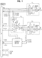
- a physical layer interface of an IEEE 1394 serial-bus node according to one embodiment of the present invention.
- the IEEE-1394 physical layer interface has an arbitration controller 10 and multiple ports for interfacing to respective serial buses.
- One of the ports is shown including a line transmitter 11, a line receiver 12 and a pair of differential line state detectors 14 and 15 of identical construction.
- Arbitration controller 10 is connected to the IEEE-1394 link layer of a computer system, not shown.
- Controller 10 has a state machine logic that drives a near-end line state on a serial bus and causes it to change according to a differential line state of the serial bus detected by the line state detectors 14, 15 from the near-end line state and a far-end line state signaled from an adjacent node.
- Line transmitter 11 and line receiver 12 are respectively connected to a target node over optical links 19 and 20 of plastic optical fiber for full duplex operation.
- Each node of the system is identically constructed and the optical links of each node are crosswired along the bus so that signals from the line transmitter 11 of a node are received by the line receiver 12 at the other node.
- a port repeater (not shown) is connected to the arbitration controller 10.
- Arbitration controller 10 automatically performs bus configuration during initial power-up of the system or when a node is attached or detached from the bus.
- Bus configuration begins with Reset and proceeds to the tree identification (Tree ID) and self identification (Self ID) stages. All nodes participate in bus configuration. Once bus configuration has completed, nodes arbitrate for access to the bus and begin normal bus transfers.
- the parallel multibit data from the arbitration controller 10 is converted to a codeword by an "mB/nB" encoder 16 of the line transmitter 11 so that the m-bit parallel data is converted to an n-bit codeword (where n > m) and converted to a serial bit stream in a parallel-to-serial converter 17 and then transformed to an optical signal by an optical transmitter 18 for transmission over the optical link 19.
- An optical serial bit stream of mB/nB format from the other node is transmitted via link 20 and received by the line receiver 12 where it is transformed to an electrical signal by an optical receiver 21 and converted to parallel form in a serial-to-parallel converter 22.
- a decoder 23 performs data conversion on the received n-bit codeword to recover original m-bit parallel data.
- the m-bit arbitration signal produced by the controller 10 is divided into higher- and lower-bit data blocks Tx_Arb of equal length and the m-bit arbitration signal from the line receiver 12 is likewise divided into higher and lower significant bits Rx_Arb of equal length.
- the multi-bit data is represented by four bits and each data block by two bits. Each two-bit data block represents one of the analog line states "Z", "0" and "1". As shown in Fig. 2, data blocks "01”, “00” and “11” represent “Z", "0” and "1", respectively.
- Differential line state detector 14 receives the lower-bit data block Tx_Arb [1:0] of a four-bit transmit arbitration signal from the arbitration controller 10 and the higher-bit data block Rx_Arb [3:2] of a four-bit arbitration signal from the line receiver 12 to produce a lower-bit data block Tx_Dif [1:0] of a four-bit pseudo-differential signal.
- the differential line state detector 15 receives the higher-bit data block Tx_Arb [3:2] of the arbitration signal and the lower-bit data block Rx_Arb [1:0] of the received arbitration signal to produce a higher-bit data block Tx_Dif [3:2] of the pseudo-differential signal.
- the differential line state detector 14 includes an exclusive-OR gate 30 to which the lower two bits of the transmit arbitration signal are applied.
- the output of the exclusive-OR gate 30 is inverted to produce a signal for enabling a transmit driver 31 which is driven by the least significant bit Tx_Arb [0].
- the higher two bits of the arbitration signal received by the line receiver 12 are supplied to an exclusive-OR gate 32 whose output is inverted for enabling a receive driver 33 which is driven by the second most significant bit Rx_Arb [2] of the received arbitration signal.
- the output of driver 31 represents the near-end line state of the serial bus and the output of driver 33 represents the far-end line state of the serial bus.
- the outputs of drivers 31 and 33 are connected together to a common circuit node 36 where a differential voltage of the near-end line state and the far-end line state is developed to synthesize a differential steady state line state as specified by the IEEE 1394 standard.
- the potential at the circuit node 36 is compared with a reference voltage R by comparators 34 and 35.
- Fig. 3 illustrates a map for establishing relationships between transmitted line states, received line states and detected pseudo-differential states, and corresponding voltage levels currently used by the data-strobe signaling.
- node A wishes to obtain ownership of the bus, it sends a four-bit request code (00 01) to node B, this code corresponding to a combination of analog line states Z and 0 respectively signaled on TPA and TPB from node A.
- the differential line state detector 15 Upon receipt of the higher significant data block "00" of the request code from the arbitration controller 10 and the lower significant data block "01" of the grant code from the line receiver 12, the differential line state detector 15 produces a higher significant data block "01” of a pseudo-differential code.
- Differential line state detector 14 responds to the lower significant data block "01” of the request code from the arbitration controller 10 and the higher significant data block “00” of the grant code from the line receiver 12 by producing a lower significant data block "01” of the pseudo-differential code.
- the differential line state code is "0101" which is presented to the arbitration controller 10.
- the state machine of the arbitration controller changes from request state to transmit state, completing the arbitration process. Once arbitration completes, the winning node initiates packet transmission which begins with "data prefix” signaling and ends with “data end” signaling.
- FIG. 4 A modified embodiment of this invention is illustrated in Fig. 4 in which parts corresponding in significance to those of Fig. 1 are marked with the same numerals, the description thereof being omitted for simplicity.
- far-end line state detectors 40 and 41 of identical structure are additionally provided to convert a received differential signal (Rx_Dif) according to the map of Fig. 5 to far-end arbitration signals (Rx_Arb) which must have been sent from the other node.
- the far-end arbitration signals (Rx_Arb) are supplied to the differential line state detectors 14 and 15 which use the map of Fig.
- the far-end line state detector 40 receives the higher significant bits Rx_Dif [3:2] of a received differential signal from the line receiver 12 and the lower significant bits Tx_Arb [1:0] of a near-end arbitration signal from the arbitration controller 10 and produces higher significant bits Rx_Arb [3:2] of a far-end arbitration signal which the other node is sending.
- Far-end line state detector 41 receives the lower significant bits Rx_Dif [1:0] of the received differential signal from the line receiver 12 and the higher significant bits Tx_Arb [3:2] of the near-end arbitration signal from the arbitration controller 10 and produces lower significant bits Rx_Arb [1:0] of the far-end arbitration signal.
- Differential line state detector 14 receives the lower significant bits Tx_Arb [1:0] of the near-end arbitration signal from the arbitration controller 10 and the higher significant bits Rx_Arb [3:2] of the far-end arbitration signal from the far-end line state detector 40 and produces higher significant bits Tx_Dif [3:2] of a near-end line state differential signal.
- the differential line state detector 15 receives the higher significant bits Tx_Arb [3:2] of the near-end arbitration signal from the arbitration controller 10 and the lower significant bits Rx_Arb [1:0] of the far-end arbitration signal from the far-end line state detector 41 and produces tower significant bits Tx_Dif [1:0] of the near-end line state differential signal.
- the exclusive-OR gate 30 receives the higher two bits of the transmit arbitration signal and the driver 31 is driven by the second most significant bit Tx_Arb [2] of the transmit arbitration signal.
- the lower two significant bits of the output of far-end line state detector 41 are supplied to the exclusive-OR gate 32 and the driver 33 is driven by the least significant bit Rx_Arb [0] of the output of far-end line state detector 41.
- the outputs of comparators 34 and 35 are supplied to the line transmitter 11 as the lower significant bits of the near-end differential signal Tx_Dif [1:0].
- Far-end line state detector 40 thus produce "01" as lower significant bits of a far-end arbitration code as indicated by broken-line rectangle 50 in Fig. 5, while the far-end line state detector 41 produces "01” as higher significant bits of the far-end arbitration code as indicated by broken-line rectangle 51 in Fig. 5.
- This far-end arbitration code (01 01) is the code which the arbitration controller 10 of node B must be producing.
- Differential line state detector 15 of node A thus produces higher significant bits "01" of a near-end differential code as indicated by broken-line rectangle 52, while the differential line state detector 14 produces lower significant bits "00" of the ear-end differential code.
- the near-end differential code is (00 01) which is presented to the line transmitter 11 and transmitted to node B which will recognize it as a request code.
- the arbitration controller 10 of node B will change from the idle state to a grant state and supplies its far-end line state detectors 40, 41 and differential line state detectors 14, 15 with a grant code (00 01) which corresponds to the analog grant state (Z, 0) as described in the previous embodiment.
- the grant code (00 01) and the differential code (00 01) being supplied from the arbitration controller 10 and the line receiver 12, the far-end line state detectors 40 and 41 of node B produce a far-end line state (00 01), recognizing that node A is sending a request code.
- the differential line state detectors 14 and 15 of node B Using the grant code (00 01) and the estimated receive code (00 01), the differential line state detectors 14 and 15 of node B produce a near-end differential code (01 01) which is transmitted to node A. Node A recognizes this signal as a grant code and changes from request state to transmit state, completing the arbitration process.
Landscapes
- Engineering & Computer Science (AREA)
- Computer Networks & Wireless Communication (AREA)
- Signal Processing (AREA)
- Small-Scale Networks (AREA)
- Information Transfer Systems (AREA)
- Dc Digital Transmission (AREA)
Applications Claiming Priority (4)
| Application Number | Priority Date | Filing Date | Title |
|---|---|---|---|
| JP26919997A JP3159145B2 (ja) | 1997-09-17 | 1997-09-17 | 送受信回路 |
| JP26919997 | 1997-09-17 | ||
| JP269199/98 | 1997-09-17 | ||
| JP26919998 | 1997-09-17 |
Publications (4)
| Publication Number | Publication Date |
|---|---|
| EP0903900A2 true EP0903900A2 (fr) | 1999-03-24 |
| EP0903900A3 EP0903900A3 (fr) | 1999-09-29 |
| EP0903900A9 EP0903900A9 (fr) | 2005-03-16 |
| EP0903900B1 EP0903900B1 (fr) | 2005-09-14 |
Family
ID=17469061
Family Applications (1)
| Application Number | Title | Priority Date | Filing Date |
|---|---|---|---|
| EP98117638A Expired - Lifetime EP0903900B1 (fr) | 1997-09-17 | 1998-09-17 | Interface pour couche physique et méthode d'arbitrage sur un bus sériel utilisant des signaux d'état de la ligne numérique |
Country Status (4)
| Country | Link |
|---|---|
| US (1) | US6324611B1 (fr) |
| EP (1) | EP0903900B1 (fr) |
| JP (1) | JP3159145B2 (fr) |
| DE (1) | DE69831540T2 (fr) |
Cited By (1)
| Publication number | Priority date | Publication date | Assignee | Title |
|---|---|---|---|---|
| EP0966130A3 (fr) * | 1998-06-19 | 2002-12-11 | Nec Corporation | Circuit d'émission-réception et processus d'auto-identification pour la communication noeud à noeud dans un réseau en bus série |
Families Citing this family (5)
| Publication number | Priority date | Publication date | Assignee | Title |
|---|---|---|---|---|
| JP2001119410A (ja) * | 1999-10-21 | 2001-04-27 | Sony Corp | 自己識別フェーズにおける処理方法 |
| JP3420136B2 (ja) | 1999-10-27 | 2003-06-23 | 日本電気株式会社 | 接続制御回路 |
| KR100419425B1 (ko) * | 2002-02-01 | 2004-02-21 | 삼성전자주식회사 | 기가비트 이더넷 - 수동 광 네트워크에서 아이들 패턴출력 제어회로 |
| US7109883B2 (en) * | 2002-09-06 | 2006-09-19 | Rosemount Inc. | Low power physical layer for a bus in an industrial transmitter |
| CN109587021B (zh) * | 2018-12-28 | 2021-05-18 | 北京强联通讯技术有限公司 | 数据传输方法及数据传输系统 |
Family Cites Families (6)
| Publication number | Priority date | Publication date | Assignee | Title |
|---|---|---|---|---|
| US4651316A (en) * | 1983-07-11 | 1987-03-17 | At&T Bell Laboratories | Data link extension for data communication networks |
| US4825402A (en) * | 1986-04-04 | 1989-04-25 | Ncr Corporation | Multiconfigurable interface driver/receiver circuit for a computer printer peripheral adaptor |
| US5717725A (en) * | 1992-03-12 | 1998-02-10 | Ntp Incorporated | System for wireless transmission and receiving of information through a computer bus interface and method of operation |
| US5742644A (en) * | 1992-03-12 | 1998-04-21 | Ntp Incorporated | Receiving circuitry for receiving serially transmitted encoded information |
| WO1994029990A1 (fr) * | 1993-06-04 | 1994-12-22 | Ntt Mobile Communications Network Inc. | Procede de detection de retard par estimation de probabilite maximum et detecteur de retard mettant en ×uvre ce procede |
| US5714904A (en) * | 1994-06-06 | 1998-02-03 | Sun Microsystems, Inc. | High speed serial link for fully duplexed data communication |
-
1997
- 1997-09-17 JP JP26919997A patent/JP3159145B2/ja not_active Expired - Fee Related
-
1998
- 1998-09-17 DE DE69831540T patent/DE69831540T2/de not_active Expired - Lifetime
- 1998-09-17 US US09/154,980 patent/US6324611B1/en not_active Expired - Fee Related
- 1998-09-17 EP EP98117638A patent/EP0903900B1/fr not_active Expired - Lifetime
Cited By (2)
| Publication number | Priority date | Publication date | Assignee | Title |
|---|---|---|---|---|
| EP0966130A3 (fr) * | 1998-06-19 | 2002-12-11 | Nec Corporation | Circuit d'émission-réception et processus d'auto-identification pour la communication noeud à noeud dans un réseau en bus série |
| US6636526B1 (en) | 1998-06-19 | 2003-10-21 | Nec Corporation | Signal sending-and-receiving circuit and self ID process for node-to-node communications in serial-bus network |
Also Published As
| Publication number | Publication date |
|---|---|
| EP0903900B1 (fr) | 2005-09-14 |
| US6324611B1 (en) | 2001-11-27 |
| JP3159145B2 (ja) | 2001-04-23 |
| JPH1198160A (ja) | 1999-04-09 |
| DE69831540D1 (de) | 2005-10-20 |
| EP0903900A3 (fr) | 1999-09-29 |
| DE69831540T2 (de) | 2006-01-19 |
Similar Documents
| Publication | Publication Date | Title |
|---|---|---|
| US6509988B1 (en) | IEEE serial bus physical layer interface having a speed setting circuit | |
| US7565470B2 (en) | Serial bus device with address assignment by master device | |
| US5206946A (en) | Apparatus using converters, multiplexer and two latches to convert SCSI data into serial data and vice versa | |
| US5160929A (en) | System for parallel communication of binary data via trinary transmission lines | |
| US4903016A (en) | Communication control unit | |
| JPH0273736A (ja) | 情報処理システム | |
| US5680113A (en) | Dynamic address assignments to serially connected devices | |
| EP0903900B1 (fr) | Interface pour couche physique et méthode d'arbitrage sur un bus sériel utilisant des signaux d'état de la ligne numérique | |
| KR100352568B1 (ko) | 케이블 길이에 무관하게 버스 리셋을 신뢰성있게 수행하는회로 및 방법 | |
| EP0905947A2 (fr) | Procédé et dispositif de modulation/démodulation | |
| KR100348508B1 (ko) | 시리얼 버스 네트워크에서 노드간 통신을 위한 신호 송수신 회로및 셀프 아이디 프로세스 | |
| JP2002507086A (ja) | 複数個のノードのためのデータバス | |
| US7076716B1 (en) | Early acknowledgement of primary packets | |
| CN100531228C (zh) | 收发装置、收发系统及收发信息的方法 | |
| KR100352567B1 (ko) | 네트워크 노드사이에서 신호를 교환하기 위한 회로 및 방법 | |
| KR970007249B1 (ko) | 데이타버스폭 변환장치 | |
| KR100235668B1 (ko) | 론웍스 네트워크 신호 변환장치 | |
| KR0179579B1 (ko) | 전동차의 광신호 전송회로 | |
| KR100493009B1 (ko) | 다중 신호 라인을 이용한 고속 직렬 버스 인터페이스 시스템 | |
| JP2737692B2 (ja) | データ送受信システム | |
| JP3438225B2 (ja) | 送受信回路 | |
| KR200220202Y1 (ko) | 모니터링 용 통신모듈 | |
| JPH03132233A (ja) | Lan通信方式 | |
| JPH06197109A (ja) | データ通信装置 | |
| JPH08313300A (ja) | エンコーダ信号通信方法 |
Legal Events
| Date | Code | Title | Description |
|---|---|---|---|
| PUAI | Public reference made under article 153(3) epc to a published international application that has entered the european phase |
Free format text: ORIGINAL CODE: 0009012 |
|
| AK | Designated contracting states |
Kind code of ref document: A2 Designated state(s): DE FR GB |
|
| AX | Request for extension of the european patent |
Free format text: AL;LT;LV;MK;RO;SI |
|
| PUAL | Search report despatched |
Free format text: ORIGINAL CODE: 0009013 |
|
| AK | Designated contracting states |
Kind code of ref document: A3 Designated state(s): AT BE CH CY DE DK ES FI FR GB GR IE IT LI LU MC NL PT SE |
|
| AX | Request for extension of the european patent |
Free format text: AL;LT;LV;MK;RO;SI |
|
| RIC1 | Information provided on ipc code assigned before grant |
Free format text: 6H 04L 29/06 A, 6H 04L 12/413 B |
|
| 17P | Request for examination filed |
Effective date: 19990823 |
|
| AKX | Designation fees paid |
Free format text: DE FR GB |
|
| 17Q | First examination report despatched |
Effective date: 20010725 |
|
| GRAP | Despatch of communication of intention to grant a patent |
Free format text: ORIGINAL CODE: EPIDOSNIGR1 |
|
| GRAS | Grant fee paid |
Free format text: ORIGINAL CODE: EPIDOSNIGR3 |
|
| GRAA | (expected) grant |
Free format text: ORIGINAL CODE: 0009210 |
|
| AK | Designated contracting states |
Kind code of ref document: B1 Designated state(s): DE FR GB |
|
| REG | Reference to a national code |
Ref country code: GB Ref legal event code: FG4D |
|
| REF | Corresponds to: |
Ref document number: 69831540 Country of ref document: DE Date of ref document: 20051020 Kind code of ref document: P |
|
| ET | Fr: translation filed | ||
| PLBE | No opposition filed within time limit |
Free format text: ORIGINAL CODE: 0009261 |
|
| STAA | Information on the status of an ep patent application or granted ep patent |
Free format text: STATUS: NO OPPOSITION FILED WITHIN TIME LIMIT |
|
| 26N | No opposition filed |
Effective date: 20060615 |
|
| PGFP | Annual fee paid to national office [announced via postgrant information from national office to epo] |
Ref country code: GB Payment date: 20090916 Year of fee payment: 12 |
|
| PGFP | Annual fee paid to national office [announced via postgrant information from national office to epo] |
Ref country code: DE Payment date: 20090910 Year of fee payment: 12 |
|
| PGFP | Annual fee paid to national office [announced via postgrant information from national office to epo] |
Ref country code: FR Payment date: 20091012 Year of fee payment: 12 |
|
| GBPC | Gb: european patent ceased through non-payment of renewal fee |
Effective date: 20100917 |
|
| REG | Reference to a national code |
Ref country code: FR Ref legal event code: ST Effective date: 20110531 |
|
| REG | Reference to a national code |
Ref country code: DE Ref legal event code: R119 Ref document number: 69831540 Country of ref document: DE Effective date: 20110401 |
|
| PG25 | Lapsed in a contracting state [announced via postgrant information from national office to epo] |
Ref country code: DE Free format text: LAPSE BECAUSE OF NON-PAYMENT OF DUE FEES Effective date: 20110401 Ref country code: FR Free format text: LAPSE BECAUSE OF NON-PAYMENT OF DUE FEES Effective date: 20100930 |
|
| PG25 | Lapsed in a contracting state [announced via postgrant information from national office to epo] |
Ref country code: GB Free format text: LAPSE BECAUSE OF NON-PAYMENT OF DUE FEES Effective date: 20100917 |