EP0903661B1 - Gerät und Verfahren zum Eingeben von Daten basierend auf visueller Erfassung - Google Patents
Gerät und Verfahren zum Eingeben von Daten basierend auf visueller Erfassung Download PDFInfo
- Publication number
- EP0903661B1 EP0903661B1 EP98306814A EP98306814A EP0903661B1 EP 0903661 B1 EP0903661 B1 EP 0903661B1 EP 98306814 A EP98306814 A EP 98306814A EP 98306814 A EP98306814 A EP 98306814A EP 0903661 B1 EP0903661 B1 EP 0903661B1
- Authority
- EP
- European Patent Office
- Prior art keywords
- visual axis
- user
- option
- display panel
- video image
- Prior art date
- Legal status (The legal status is an assumption and is not a legal conclusion. Google has not performed a legal analysis and makes no representation as to the accuracy of the status listed.)
- Expired - Lifetime
Links
Images


Classifications
-
- G—PHYSICS
- G06—COMPUTING OR CALCULATING; COUNTING
- G06F—ELECTRIC DIGITAL DATA PROCESSING
- G06F3/00—Input arrangements for transferring data to be processed into a form capable of being handled by the computer; Output arrangements for transferring data from processing unit to output unit, e.g. interface arrangements
- G06F3/01—Input arrangements or combined input and output arrangements for interaction between user and computer
- G06F3/011—Arrangements for interaction with the human body, e.g. for user immersion in virtual reality
- G06F3/013—Eye tracking input arrangements
-
- A—HUMAN NECESSITIES
- A61—MEDICAL OR VETERINARY SCIENCE; HYGIENE
- A61F—FILTERS IMPLANTABLE INTO BLOOD VESSELS; PROSTHESES; DEVICES PROVIDING PATENCY TO, OR PREVENTING COLLAPSING OF, TUBULAR STRUCTURES OF THE BODY, e.g. STENTS; ORTHOPAEDIC, NURSING OR CONTRACEPTIVE DEVICES; FOMENTATION; TREATMENT OR PROTECTION OF EYES OR EARS; BANDAGES, DRESSINGS OR ABSORBENT PADS; FIRST-AID KITS
- A61F4/00—Methods or devices enabling patients or disabled persons to operate an apparatus or a device not forming part of the body
Definitions
- the present invention relates to a visual axis entry transmission apparatus, and to a method for detecting the line of sight (visual axis) from a user to a display panel and for inputting the result of the detection of the line of sight as information to be shown on a display panel in order to communicate the intent of the user.
- a visual axis entry transmission apparatus has been proposed, and is in practical use, that detects the line of sight from a user to a display panel, and inputs the result of the detection of the line of sight as information to be shown on the display panel so as to communicate the intent of the user.
- a well known visual axis entry transmission apparatus displays 50 kana characters, alphabetical characters, etc., on a monitor, analyzes a user's visual axis location by obtaining images of the eyeballs of the user with a camera, and then, to perform character input, identifies the character in a character table at the terminus of the visual axis.
- British Patent GB 2281838 describes an apparatus in which the user's line of sight, as determined by a visual axis detection device, is used to select an item from a menu bar displayed within a virtual-reality scene generated by the apparatus.
- the present invention provides a visual axis entry transmission apparatus as set out in claim 1.
- the present invention provides a visual axis entry transmission method as set out in claim 43.
- FIGs. 1A and 1B are a top view and a side view for explaining the principle of a visual axis detection method.
- IRED 906a and 906b emit infrared light that is not sensed by a user. These light sources are located substantially symmetrically in direction x (the horizontal direction) relative to the light axis of a focusing lens 911, and sightly downward in direction Y (the vertical direction). One part of the emitted light reflected by an eyeball 908 of the user is passed through the focusing lens 911 and forms an image on an image sensor 912.
- Figs. 2A and 2B are diagrams showing the image of the eyeball 908 that is projected onto the image sensor 912, and the intensity of the signal.
- the infrared light emitted by the light source 906a illuminates a cornea 910 of an eyeball 908 of a user
- a reflected corneal image d (virtual image) is formed by the infrared light reflected on the surface of the cornea 910 and is concentrated by the focusing lens 911 to form an image at position d' on the image sensor 912.
- the infrared light emitted by the light source 906a illuminates the cornea 910 of the eyeball 908.
- a reflected corneal image e (a virtual image) is formed by the infrared light reflected onto the surface of the cornea 910, and is concentrated by the focusing lens 911 to form an image at position e' on the image sensor 912.
- Light fluxes reflected from edges a and b of an iris 904 are passed through the focusing lens 911 and form images at positions a' and b' on the image sensor 912.
- ⁇ is a magnification rate determined by the distance "sze" from the focusing lens 911 to the eyeball 908, and is actually obtained as a function for a distance between the reflected corneal images,
- the corneal images reflected by the two IREDs 906a and 906b are formed at the same position, which is defined as i.
- the method used for calculating rotation angle ⁇ y of the eyeball 908 is substantially the same as that used for the horizontal plane, except that equation (2) differs.
- y coordinate of the corneal curvature center o is defined as yo
- xn m ⁇ arcsin[[xc' - ⁇ (xd'+xe')/2+ ⁇ x' ⁇ ]/oc/ ⁇ ]
- yn m ⁇ arcsin[[yc' - ⁇ (yi' + ⁇ y')]/oc/ ⁇ ]
- the trailing edge (xb') and the leading edge (xa') of a waveform output by the image sensor 912 are employed to detect the edges of the pupil. Furthermore, the peaks of the sharp leading edges (xe') and (xd') are employed to obtain the coordinates of the reflected corneal image.
- a personal computer system having a visual axis detection function will now be described as an example visual axis entry transmission apparatus.
- Fig. 3 is a schematic diagram illustrating the arrangement of a personal computer system having a visual axis detection function.
- the personal computer system comprises a computer unit 1008, which is the main body of a personal computer; a head-mounted display unit 1006, with which an operator can view the screen of the personal computer; and an external monitor 1009, with which an operator or another user can view the screen of the computer.
- the head-mounted display unit 1006 is, for example, a pair of goggles or a glass frame that is supported near the eyes of the operator.
- the head-mounted display unit 1006 comprises a liquid crystal display device 1002; a special prism 1003, which serves as an enlarging observation system; a visual axis detection circuit 1064 for detecting the line of sight of the eyes 1005 of the operator; a liquid crystal display circuit 1007, for displaying a computer screen on the liquid crystal display device 1002; infrared light emitting diodes 1060 and 1061, for irradiating with infrared light both of the eyes 1005 of the operator; focusing lens 1062a and 1062b for collecting the infrared light reflected by the eyeballs; and a photoelectric converter 1063 for converting the infrared light transmitted by the focusing lens 1062 into an electric signal.
- a focus point detection circuit is provided for the visual axis detection circuit 1064 in order to detect the focus point of the operator on the liquid crystal display device 1002, in accordance with the images of the eyeballs of the operator that are displayed on the photoelectric converter 1063.
- the line that connects the eye 1005 of the user and the center of the liquid crystal display device 1002 is designated the basic light axis.
- the liquid crystal display device 1002 is moved in parallel with the light axis of the prism 1003 to enable it to be adjusted to the vision of the user.
- the faces of the prism 1003 be three-dimensional curved faces that do not have rotation axes so as to provide a telecentric prism system that compensates for the image focusing and image distortion performances. Therefore, the prism 1003 has a curved structure that includes a basic light axis and is symmetric only to a plane that is parallel to the face of a sheet of paper.
- the optical operation of the visual axis detection system in the head-mounted display unit 1006 will now be described.
- Lights are emitted by the infrared light emitting diodes 1060 (two diodes provided to the rear of the face of a sheet of paper) for eyes without corrective lenses and the infrared diodes 1061 (two diodes also provided to the rear of the face of the sheet of paper) for eyes with corrective lenses, are passed through openings 1012, 1013, 1014 and 1015 that are formed in the second optical face b, and illuminate the eyes of the user in a direction that differs from the light axis of the visual axis detection system.
- the illuminating lights are reflected by the pupils and scattered.
- the eye image obtained by the image sensor 1063 is transmitted to the visual axis detection circuit 1064, which is constituted based on the visual axis detection principle previously mentioned.
- the visual axis detection circuit 1064 then outputs focusing point data.
- the focusing lens system 1062 consists of two lenses 1062a and 1062b. Especially because the lens 1062a is wedge-shaped, only a small number of lenses are required to constitute the focusing lens system, which is appropriate for reducing. When a curvature is provided for the sloping face of the lens, an eccentric aberration that occurs at the second optical face b can effectively be compensated for. Furthermore, when at least one aspheric face is provided for the focusing lens, it can effectively compensate for the image focusing performance in the space surrounding the axis.
- the size of the opening 1010 can be smaller, and a transfer hollow in the observation system can be prevented. Therefore, it is preferable that the positions of the opening and of the aperture correspond to each other.
- the opening 1010 is formed so that it is smaller than 2 mm, it is smaller than the pupil of the eye, and a transfer hollow for the user can be prevented.
- the infrared light is employed. At this time, if at least one lens for reducing the visible light is provided for the focusing lens system, the accuracy can be increased for the detection of a visual axis.
- Fig. 4 is a side view of the shape of the prism 1003. Reflective mirror coating is applied only to the optical face b and is not applied to the opening 1010 for the focusing lens system 1062 and the openings for the infrared light emitting diodes 1060 and 1061 (the openings 1012 and 1013 for the infrared light emitting diodes for eyes without corrective lenses and the openings 1014 and 1015 for the infrared light emitting diodes for eyes with corrective lenses).
- non-mirror coated sections are too small to affect the viewfinder observation system, and their diameters are preferably equal to or smaller than 2 mm. Since the openings are formed in the mirror coated section, and the prism 1003 is positioned between the eyes and the light sources that are located opposite the eyes, even when the refractivity of the prism 1003 is increased and visibility is enhanced, the light sources can adequately illuminate the eyes when they are located at a position near the height of the eyes.
- the infrared light emitting diodes for eyes without corrective lenses and for eyes with corrective lenses are located at different positions.
- the two infrared light emitting diodes 1060 for eyes without corrective lenses are located on either side of the optical face b, at the same height, as measured from the lower edge, and slightly separate, by a small interval, from the light axis, and are symmetrically arranged along the light axis. There are three reasons for this. The first reason is that to obtain a better illumination condition in accordance with the distance from the eyeballs, the infrared light emitting diodes are so located that they equally illuminate the eye detection area.
- the second reason is that the location of the diodes must be higher enough that the reflected corneal images are not obtained at the eyelids, and so that the infrared light emitting diodes for eyes without corrective lenses are positioned higher than the infrared light emitting diodes for eyes with corrective lenses.
- the third reason is to permit a ghost that is produced when the infrared light is reflected by corrective lenses to appear only at the periphery where its detection will have little effect.
- the infrared light emitting diodes for eyes with corrective lenses are positioned horizontally and vertically apart from those for eyes without corrective lenses.
- the identification of eyes without corrective lenses and eyes with corrective lenses is performed by calculating the distance between the lenses and the prism 1003 using the interval
- the visual axis detection circuit 1064 ascertains the operator's point of focus on the screen of the liquid crystal display device 1002.
- the personal computer unit 1008 comprises: a CPU 1814, which performs the program based data computation; a system bus 1813, for connecting the individual devices; a memory controller 1818 for controlling a ROM 1816 and a RAM 1817; a video graphic controller 1812 for displaying data stored in a RAM 1811 on a display screen; an accessory device controller 1815, which controls a pointing device and a keyboard and which is connected to the visual axis detection circuit 1064 of the head-mounted display unit 1006 in this embodiment; and an I/O channel 1819, which controls peripheral devices and which is connected to the liquid crystal display circuit 1007 of the head-mounted display unit 1006 in this embodiment.
- the operator's visual axis location position which is ascertained by the visual axis detector 1064 of the head-mounted display unit 1006, can be employed as a pointing device by the personal computer unit 1008, and can also be employed to scroll the screen and to make menu selections.
- the computer screen can be displayed on the external monitor 1009, a person other than the operator can view it.
- a head-mounted display unit for use by a single eye may be employed, and in this case, the operator can also view the external monitor 1009.
- FIG. 5 is a conceptual diagram showing the operating state of the visual axis entry transmission apparatus.
- the head-mounted display unit 1006 incorporates a visual axis detection circuit.
- a computer 4 is constituted by the personal computer unit 1008 and the external monitor 1009.
- An adaptor 31 is used to connect the head-mounted display unit 1006 and the computer 4, and to supply power to the head-mounted display unit 1006.
- a user 1 of the system wears the head-mounted display unit 1006 in the same manner as are glasses, and can view a video image 3 generated by the computer 4.
- the visual axis data detected by the visual axis detection circuit in the head-mounted display unit 1006 are transmitted to the computer 4.
- the user 1 can use the head-mounted display unit 1006 to view the video image 3 generated by the computer 4, and can issue specific instructions using his line of sight (the movement of his eyes).
- the user 1 in the video image 3 projected onto the display panel, which comprises hiragana, katakana, alphabetical characters and numerals that are generated by the computer 4, the user 1 can input individual characters by focusing on them, and can create sentences and engage in a conversation.
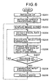
- Fig. 6 is a flowchart showing the processing performed by a visual axis entry transmission program. This program is stored in the ROM 1816 of the personal computer unit 1008, and is executed by the CPU 1814.
- an I/F for a communication line is initialized (step S201).
- a serial port RS232C is opened and is set to the communication enabled state.
- a speech processing unit is initialized (step S202).
- hiragana characters or katakana or alphabetical characters
- a display controller 31 on the liquid crystal device 1002 of the head-mounted display unit (visual axis input scouter) 1006 and on the external monitor 1009 (step S203).
- Fig. 7 is a diagram showing the video image projected onto the display panel provided by the liquid crystal display device 1002 and by the external monitor 1009. The options listed on the display panel will be described later.
- step S204 the visual axis position is detected (step S204), and a character at the visual axis position is obtained based on the detected visual axis position data (step S205). Selection character data for the past 100 selections are then updated (step S206).
- the character entry condition is that, of the character data in the past 100 selections, the number of selections of pertinent character data equals a number that corresponds to the period of time during which the visual axis must be positioned at the same character in order for it to be entered, or is equal to a number that corresponds to a constant ratio of the length of time during which the visual axis is positioned at the same character to a predetermined period of time.
- step S207 When, at step S207, the character entry condition is satisfied, a character is added to an input character string (step S208), and the newly input character is pronounced (step S209) to notify the user that the character entry has been completed.
- Program control thereafter returns to step S203 to display the screen for the selection of a new input character.
- step S207 When, at step S207, the character entry condition is not satisfied, program control returns to step S204, whereat a new visual axis position is detected to repeat the selection of the character.
- the operator can enter a character regardless of his or her posture, and it is easy for a seriously physically handicapped person to enter a character.
- step S206 whether or not the character entry condition is satisfied is determined by counting the number of times the visual axis is positioned at the same character.
- the timer may be started when the visual axis is positioned at a character and the time length measured.
- the user may set an arbitrary ratio for the length of time the visual axis remains on a character to a predetermined period of time, so that the useability can be increased.
- Fig. 8 is a conceptual diagram showing the use of a visual axis entry transmission apparatus according to a second embodiment of the present invention.
- the same reference numerals as are used for the first embodiment are also used in this embodiment to denote corresponding or identical components.
- a pair of visual axis entry glasses 102 incorporates a visual axis detection circuit, and has the same internal arrangement as has the previously mentioned head-mounted display unit 1006, with the exception that the portion for displaying a video image 3 is excluded.
- a user 1 wears the visual axis entry glasses 102 and views a video image 3 of a display panel using a monitor 6 of a computer 4.
- Visual axis position data are detected by the visual axis detection circuit in the visual axis entry glasses 102, and are transmitted to the computer 4. That is, the user 1 can view a video image 3 generated on the monitor 6 by the computer 4, and can instruct a specific operation by moving the visual axis (by moving the eyeballs).
- the user 1 can input individual characters by focusing on them, and can create sentences and engage in a conversation.
- the user can enter a character, while viewing the video image 3 of the display panel on the monitor 6 with the visual axis entry glasses 102, so that the input operation can be performed in a near to natural manner.
- Fig. 9 is a conceptual diagram illustrating the use of a visual axis entry transmission apparatus according to a third embodiment of the present invention.
- the same reference numerals as are used in the first and the second embodiments are also used in this embodiment to denote corresponding or identical components.
- a pair of visual axis input glasses 102 incorporates a visual axis detection circuit. Also provided are a magnetic field generator 7, such as a magnet, and a magnetic sensor 8. With this system, a user 1 wears the visual axis entry glasses 102 and the magnetic field generator 7, and views a video image 3 on a monitor 6 of a computer 4.
- An induction current is generated at the magnetic sensor 8 by a magnetic field that is produced by the magnetic field generator 7, and as the magnitude of the current is controlled by the computer, data can be obtained for the position and the angle of the head of the user 1.
- the visual axis position data which are detected by the visual axis detection circuit of the visual axis entry glasses 102, and the position and angle data for the head of the user, which are obtained by the magnetic sensor 8, are transmitted to the computer 4.
- the user 1 can view a video image 3 generated on the monitor 6 by the computer 4, and can instruct a specific operation by moving the visual axis (by moving the eyes), while he or she employs the head position and angle data to correct an error in the visual axis position data that is caused by moving the head.
- the user 1 can input individual characters by focusing on them, and can create sentences and engage in a conversation.
- an error in the visual axis position data that is caused by moving the head can be corrected, and the number of character input errors can be reduced.
- Fig. 10 is a conceptual diagram illustrating the use of a visual axis entry transmission apparatus according to a fourth embodiment of the present invention.
- the same reference numerals as are used for the first and the second embodiments are also used in this embodiment to denote corresponding or identical components.
- a pair of visual axis entry glasses 102 incorporates a visual axis detection circuit.
- a user 1 wears the visual axis entry glasses 102, and views a video image 3 projected onto a screen 107 by a projection device 106.
- the visual axis position data are detected by the visual axis detection circuit of the visual axis entry glasses 102 and are transmitted to the computer 4.
- the user 1 can view the video image 3 generated on the screen 107 by the computer 4, and can instruct a specific operation by moving the visual axis (by moving the eyes).
- the display panel video image 3 that is generated by the computer 4 and that consists of hiragana or katakana, alphabetical characters and numerals
- the user 1 can input individual characters by focusing on them, and can create sentences and engage in a conversation.
- the eyes of the user 1 do not become very tired, even though the user continues to view the video image 3 for an extended period of time.
- Fig. 11 is a conceptual diagram illustrating the use of a visual axis entry transmission apparatus according to a fifth embodiment of the present invention.
- the same reference numerals as are used in the first, the second and the fourth embodiments are also used in this embodiment to denote corresponding or identical components.
- a pair of visual axis input glasses 102 incorporates a visual axis detection circuit. Also provided are a magnetic field generator 7, such as a magnet, and a magnetic sensor 8. With this system, a user 1 wears the visual axis entry glasses 102 and the magnetic field generator 7, and views a video image 3 projected onto a screen 107 by a projection device 106.
- An induction current is generated at the magnetic sensor 8 by a magnetic field that is produced by the magnetic field generator 7, and as the magnitude of the current is controlled by the computer, data can be obtained for the position and the angle of the head of the user 1.
- the visual axis position data which are detected by the visual axis detection circuit of the visual axis entry glasses 102, and the position and angle data for the head of the user, which are obtained by the magnetic sensor 8, are transmitted to the computer 4.
- the user 1 can view the video image 3 generated on the screen 107 by the computer 4, and can instruct a specific operation by moving the visual axis (by moving the eyes), while he or she employs the head position and angle data to correct an error in the visual axis position data that is caused by moving the head.
- the user 1 can input individual characters by focusing on them, and can create sentences and engage in a conversation.
- FIG. 12 is a flowchart showing the processing performed by a visual axis entry transmission program according to the sixth embodiment of the present invention. This program is stored in the ROM 1816 of the personal computer unit 1008, and is executed by the CPU 1814.
- an I/F for a communication line is initialized (step S801).
- a serial port RS232C is opened and is set to the communication enabled state.
- a speech processing unit is initialized (step S802). Following which 50 hiragana characters (see Fig. 7), or katakana or alphabetical characters, are displayed via a display controller 31 on the liquid crystal device 1002 of the head-mounted display unit (visual axis input scouter) 1006 and on the external monitor 1009 (step S803).
- the visual axis position data are detected (step S804), and are employed to determine whether a user's eyes are closed (step S805).
- the visual axis data indicate the user's eyes are not closed, a character at the visual axis position is obtained based on the visual axis position data obtained at step S804 (step S811).
- the obtained character is compared with a previously selected character to determine whether the two characters are the same (step S812).
- a counter value is incremented by one (step S813).
- a check is performed to determine whether the updated counter value is equal to or greater than a preset value (step S814).
- step S815 When the counter value is equal to or greater than the preset value, an input enabling flag is set to "1" (step S815).
- the processes at steps S812, S813, S814 and S815 are performed in order to prevent a visual axis entry at the moment the user closes his or her eyes, and the erroneous input of a character that is not selected by the user.
- step S814 the counter value does not reach the preset value, program control returns to step S804.
- step S812 When, as a result of the comparison performed at step S812, the recently input character differs from the previously selected character, the selected character is updated (step S816) and the counter is reset (step S817). Program control thereafter returns to step S804.
- step S805 When at step S805 the visual axis position data indicate the user's eyes are closed, the counter value is incremented by one (step S806).
- a check is then performed to determine whether the counter value is equal to or greater than the preset value (step S807).
- the counter value is equal to or greater than the preset value, and the input enabling flag is set to "1"
- the counter is reset (step S808).
- a character entry process is performed in the same manner as is the input confirmation method for maintaining the visual axis for a predetermined period of time (step S809), and voice is output (step S810). Program control thereafter returns to step S803.
- the input data are confirmed by closing the eyes
- eye fatigue can be reduced compared with when the input data are confirmed by maintaining the visual axis for a specific period of time.
- the period during which the eyes are closed i.e., the blinking period, can be changed, as will be described later.
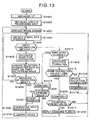
- Fig. 13 is a flowchart showing the processing performed by a visual axis entry transmission program according to the seventh embodiment of the present invention.
- an I/F for a communication line is initialized (step S1401).
- a serial port RS232C is opened and is set to the communication enabled state.
- a speech processing unit is initialized (step S1402).
- hiragana characters see Fig. 7
- katakana or alphabetical characters are displayed via a display controller 31 on the liquid crystal device 1002 of the head-mounted display unit 1006 and on the external monitor 1009 (step S1403).
- the visual axis position data are detected (step S1404), and a check is performed to determine whether the currently selected input confirmation method is a method that requires the visual axis to be maintained for a specific period of time, or a method that requires the closing of eyes (step S1405).
- Fig. 14 is a diagram showing a screen for changing the input confirmation method. Using this screen, the user 1 can select the input confirmation method to be used, either the method that requires the closing of eyes (blinking), or the method that requires the maintenance of the visual axis for a specific period of time. It should be noted that one of the input confirmation methods that are already set is selected.
- a visual axis maintenance period When changing the input confirmation method, a visual axis maintenance period, a blinking time, or the number of characters on the display panel (keyboard) can also be changed.
- Fig. 15 is a screen for changing the maintenance time for the input confirmation method that requires the maintenance of the visual axis for a specific period of time.
- the visual axis maintenance period can be set as units of seconds, of from 3 to 7 seconds.
- the current visual axis maintenance period, displayed with inverse video is "6 seconds"
- a currently selected period, enclosed by a double frame is "4 seconds”.
- the enter key on the keyboard is pressed, the visual axis maintenance period will be changed from six seconds to four seconds.
- the time can be changed by using an arrow key on the keyboard.
- Fig. 16 is a diagram showing a screen for changing the blinking time for the input confirmation method that requires the closing of the eyes.
- the blinking time can be set as units of seconds ranging from 1 to 5 seconds, and the user 1 can use this screen to change the blinking time.
- Fig. 17 is a diagram showing a screen for changing the number of characters on the display panel. The user 1 can use this screen to select the number of characters to be shown on the display panel (6 lines and 6 rows, or 6 lines and 7 rows).
- the options shown in inverse video are the ones that are currently set, and the options that are enclosed in a double frame are the ones that have newly been selected. The same process is applied for the following display examples.
- step S1405 An explanation will now be given for a process where, at step S1405, an input character is confirmed by the method for which the visual axis is maintained for a specific period of time.
- the visual axis position data obtained at step S1404 are employed to acquire a character at the visual axis position (step S1406).
- Data for the selected character are updated when it was one of the last 100 selections (step S1407).
- a check is performed to determine whether the condition for the entry of a character is satisfied by this new character selection (step S1408).
- the character entry condition is that, of character data in the last 100 selections, the number of selections of the pertinent character data exceeds the number that corresponds to the period of time the visual axis must be positioned on the same character for it to be entered, or it exceeds the number that corresponds to a constant ratio of the length of time the visual axis is positioned on the same character to a predetermined period of time.
- step S1408 When, at step S1408, the character entry condition is satisfied, a character is added to an input character string (step S1409), and the newly input character is pronounced (step S1410) in order to notify the user that the entry of the character has been completed.
- Program control thereafter returns to step S1403 to display the screen for a new input character.
- step S1408 When, at step S1408, the character entry condition is not satisfied, program control returns to step S1404, whereat a new visual axis position is detected to repeat the selection of a character.
- step S1405 the method for the closing of the eyes is selected as the input confirmation method, a check is performed to determine whether the visual axis position data obtained at step S1404 are those indicating the user's eyes are closed (step S1411).
- a character at the visual axis position is obtained based on the visual axis position data obtained at step S1404 (step S1412). That character is compared with a previously selected character to determine whether the two characters are the same (step S1413). When the two characters are the same, a counter value is incremented by one (step S1416).
- step S1417 a check is performed to determine whether the updated counter value is equal to or greater than a preset value.
- an input enabling flag is set to "1" (step S1418).
- the processes at steps S1413, S1416, S1417 and S1418 are performed in order to prevent a visual axis entry at the moment the user closes his or her eyes, and the erroneous input of a character that is not selected by the user.
- step S1417 the counter value does not reach the preset value
- program control returns to step S1404.
- step S1413 When, as a result of the comparison at step S1413 the currently input character differs from the previously selected character, the selected character is updated (step S1414) and the counter is reset (step S1415). Program control thereafter returns to step S1404.
- step S1411 When at step S1411 the visual axis position data indicate that the user's eyes are closed, the counter value is incremented by one (step S1419). A check is performed to determine whether the counter value updated at step S1419 is equal to or greater than the preset value and whether the input enabling flag was set to "1" at step S1418 (step S1420).
- step S1421 When the counter value is equal to or greater than the preset value and the input enabling flag is set to "1”, the counter is reset (step S1421). Program control moves to step S1409, whereat a character entry process is performed in the same manner as the input confirmation method whereby the visual axis must be maintained for a predetermined period of time.
- step S1420 When, at step S1420, the counter value is smaller than the preset value and the input enabling flag is not set to "1", program control returns to step S1404.
- the usability can be increased.
- a visual axis entry transmission apparatus can change from a character selection screen to a TV broadcast scene by selecting an option on a character selection screen, and is applied to the first to the seventh embodiments.
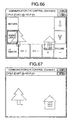
- Fig. 18 is a diagram showing a TV broadcast scene when an option for a TV is selected on the character selection screen.
- the TV broadcast scene is displayed as a video for the first to the seventh embodiments.
- options 2G to 7G are displayed.
- Fig. 19 is a diagram showing the TV broadcast scene with the options displayed.
- the screen is returned to the character selection screen in Fig. 7.
- the option 3G the TV broadcast scene is changed to that at a smaller channel number.
- the option 4G the TV broadcast scene is changed to that at a greater channel number.
- the option 5G the volume is lowered.
- the option 6G the volume is increased.
- the option 7G the TV video is displayed on the entire monitor screen.
- the user can select a desired screen by changing the display panel for character entry and the TV broadcast screen.
- TV video not only the TV video, but also an externally input video image from a video recorder, a computer, a video-on-demand device, a clock, a crime prevention device or a video telephone, may be selected, so that the user can freely select various types of videos.
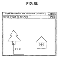
- an external environment control screen may be provided to control an external environment device.
- the user can freely control external environment devices, such as lighting apparatuses, televisions, audio devices, video recorders, computers, video-on-demand devices, telephones, video telephones, clocks, electric blinds, electric curtains, electric window opening/closing devices, air conditioners, crime prevention devices, electric reclining beds, excretion devices, lifters and nurse calling devices.
- external environment devices such as lighting apparatuses, televisions, audio devices, video recorders, computers, video-on-demand devices, telephones, video telephones, clocks, electric blinds, electric curtains, electric window opening/closing devices, air conditioners, crime prevention devices, electric reclining beds, excretion devices, lifters and nurse calling devices.
- the arrangement of an apparatus according to a ninth embodiment is the same as that in the first embodiment.
- the user can adjust the visibility: the user moves the visual axis upward on the screen in order to increase the visibility, and moves the visual axis downward on the screen in order to reduce the visibility. To terminate the adjustment of the visibility, the user moves the visual axis to the center on the screen.
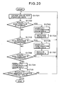
- Fig. 20 is a flowchart showing the visibility adjustment processing according to the ninth embodiment.
- the program is stored in a ROM 1816 and is executed by a CPU 1814.
- visual axis position data are acquired by a visual axis detection circuit (step S1701).
- a check is then performed to determine whether the visual axis position data obtained at step S1701 indicate a value higher than the preset value (step S1702).
- step S1703 When the visual axis position data indicate a value higher than the preset value, the visibility counter used for establishing the visibility is set to "0" (step S1703). Thereafter a computer 4 transmits a command to a head-mounted display unit 1006 to increase the visibility (step S1704). Program control thereafter returns to step S1701.
- step S1705 When, at step S1702, the visual axis position data are not higher than the preset value, a check is performed to determine whether the visual axis position data are lower than the preset value (step S1705). When the visual axis position data are lower than the preset value, the visibility counter used for establishing the visibility is set to "O" (step S1706), and the computer 4 issues a command to the head-mounted display unit 1006 to reduce the visibility (step S1707). Program control thereafter returns to step S1701.
- step S1705 When, at step S1705, visual axis position data below the preset value are not present, a check is performed to determine whether the visual axis position data are in a preset area in the center on the screen (step S1708).
- the visibility counter value is incremented by one (step S1709). Then, a check is performed to determine whether the visibility counter value is greater than the preset value (step S1710). When the visibility counter value is greater than the preset value, it is assumed that the visibility has been adjusted, and the processing is thereafter terminated.
- step S1710 When, at step S1710, the visibility counter value is equal to or smaller than the preset value, program control returns to step S1701. And when, at step S1708, the visual axis position data are not located in the preset area in the center on the screen, program control also returns to step S1701.
- the visibility can be adjusted to suit the user.
- the arrangement of an apparatus according to a tenth embodiment is the same as that in the first embodiment, except that in the tenth embodiment a switch (not shown) used to confirm an input character is connected to an I/O channel 1819.
- This program is stored in the ROM 1816 of the personal computer unit 1008 and is executed by the CPU 1814.
- Fig. 21 is a flowchart showing the processing of a visual axis entry transmission program according to the sixth embodiment of the present invention.
- an I/F for a communication line is initialized (step S1801).
- a serial port RS232C is opened and is set to the communication enabled state.
- a speech processing unit is initialized (step S1802).
- 50 hiragana characters are displayed via a display controller 31 on the liquid crystal device 1002 of the head-mounted display unit (visual axis input scouter) 1006 and on the external monitor 1009 (step S1803).
- step S1804 the visual axis position data are detected.
- a check is performed to determine whether a switch for confirming the entry has been depressed (step S1805).
- a character at the visual axis position is obtained based on the visual axis position data (step S1811).
- That character is compared with the previously selected character to determine whether the two characters are the same (step S1812).
- a counter value is incremented by one (step S1813).
- a check is performed to determine whether the updated counter value is equal to or greater than a preset value (step S1814).
- an input enabling flag is set to "1" (step S1815).
- step S1814 When at step S1814 the counter value does not equal the preset value, program control returns to step S1804.
- the selected character is updated (step S1816) and the counter is reset (step S1817). Program control thereafter returns to step S1804.
- step S1805 When at step S1805 the switch for confirming the entry has been depressed, the counter value is incremented by one (step S1806). A check is then performed to determine whether the counter value incremented at step S1806 is equal to or greater than the preset value and whether the input enabling flag is set to "1" (step S1807). When the counter value is equal to or greater than the preset value and the input enabling flag is set to "1", the counter is reset (step S1808). A character entry process is performed in the same manner as the input confirmation method for which the visual axis is maintained for a predetermined period of time (step S1809), and voice is output (step S1810). Program control thereafter returns to step S1803.
- step S1807 When at step S1807 the counter value is smaller than the preset value, program control returns to step S1804.
- the operation requiring the use of the eyes can be reduced.
- the switch may be worn on the head, or may be held in a hand.
- the user may set an arbitrary period of time during which the switch must be depressed before the selected character is confirmed. Since an adequate on-time period for the switch is set for each user, the useability can be enhanced.
- Fig. 22 is a diagram showing the first page for the hiragana character selection screen
- Fig. 23 is a diagram showing the second page for the hiragana character selection screen
- Fig. 24 is a diagram showing the third page for the hiragana character selection screen.
- the individual options on the character selection screen are as follows:
- Fig. 25 is a diagram showing function selection screen 1 displayed when the user selects "Function" on the character selection screen
- Fig. 26 is a diagram showing function selection screen 2.
- the user selects options to change various preset values for the visual axis entry transmission apparatus.
- the screen is returned to the character selection screen (see Fig. 22).
- the shift from the function selection screen 1 to the function selection screen 2 can be performed by selecting " ⁇ " on the function selection screen 1.
- the shift from the function selection screen 2 to the function selection screen 1 can be performed by selecting " ⁇ ".
- Fig. 27 is a flowchart showing the calibration processing.
- a status variable (NAC_STAT) for calibration is initialized (step S302).
- the screen is cleared (step S303)
- the message for performing calibration is displayed (step S304).
- the left index is displayed at a position where theoretically the eyeball is inclined six degrees from the front to the left (step S305), and the left calibration data are acquired (step S306).
- a check is performed to determine whether the acquisition of the left calibration data was successful (step S307).
- the status variable (NAC_STAT) is initialized again (step S308). Program control thereafter returns to step S305.
- step S309 When the acquisition of the left calibration data was successful, a statement to that effect is displayed, and the right index is displayed at a position where theoretically the eyeball is inclined six degrees from the front to the right (step S309), and the right calibration data are acquired (step S310). A check is performed to determine whether the acquisition of the right calibration data was successful (step S311). When the acquisition of the right calibration data failed, the status variable (NAC_STAT) is initialized again (step S312). Program control thereafter returns to step S309.
- NAC_STAT the status variable
- the calibration is performed when the visual axis entry transmission apparatus is activated, or when "Calibration" on the function selection screen 1 is selected.
- Fig. 28 is a flowchart showing the entry processing when, to take a recess, a user clears the screen and narrows a visual axis entry available range.
- visual axis position data are acquired in synchronization with the timer (step S402).
- a check is then performed to determine whether the visual axis entry is restricted (step S403).
- step S404 When the visual axis entry is not restricted, the normal visual axis entry process is performed (step S404). When the visual axis entry is restricted, a check is performed to determine whether the visual axis position is within a range wherein the visual axis position can be displayed (step S405). When the visual axis position is outside that range, the processing is terminated.
- step S406 If the visual axis position is within the range where the visual axis position can be displayed, that position is displayed (step S406). A check is then performed to determine whether the visual axis position is within an option cell (step S407). When the visual axis position is outside the option cell, the processing is terminated.
- step S408 If the visual axis position is within the option cell, the cell selection processing is performed (step S408). Thereafter, the processing is terminated.
- Fig. 29 is a diagram showing the normal input screen in the recess mode. In the recess mode, option cells are not displayed, except for a "Return" cell for returning to the normal input screen.
- the user can recess a session by selecting "Recess" on the function selection screen 1, by closing his, or her, eyes for a predetermined period of time, by staring at one of the corners on the screen; or by entering data using the input confirmation condition process. Further, the direction in which the user's line of sight is directed may be arbitrarily changed, so that usability can be improved.
- Fig. 30 is a diagram showing a screen that the user can employ for changing the volume.
- the amplitude of a speech waveform is 1/5 times that of the "Ordinary” level.
- the amplitude of the waveform is reduced to 1/2 times that of the "Ordinary” level.
- the amplitude of the waveform is doubled, and when "High” is selected, the amplitude of the waveform is increased five times.
- the user selects "Change volume” on the function selection screen 1.
- Fig. 31 is a diagram showing a screen the user can employ to change the pronouncing speed.
- the speed is 170 msec/mora; when “A Little slow” is selected, the speed is 150 msec/mora; when “Ordinary” is selected, the speed is 130 msec/mora; when “A Little Fast” is selected, the speed is 110 msec/mora; and when “Fast” is selected, the speed is 90 msec/mora.
- “Change Pronouncing Speed” is selected on the function selection screen 1.
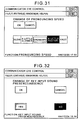
- Fig. 32 is a diagram showing a screen for setting or canceling the function for uttering the name of a choice (option) when it is selected.
- “Yes” is selected, the name of a choice is uttered at the time it is selected.
- "No” is selected, the name of a choice is not uttered, even when it is selected. In either case, a sentence that has been created is uttered when "Utterance" is selected.
- Fig. 33 is a diagram showing a screen for changing the invalid time. On this screen the user can select the timing for the invalid time. To change the invalid time, "Change maintenance time" is selected on the function selection screen 1.
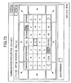
- Fig. 34 is a diagram showing a screen for changing the overall size of a keyboard
- Fig. 35 is a diagram showing a screen for changing the size of a keyboard in the horizontal direction.
- the user selects "Up/Down” or "Left/Right" to change the size of the keyboard (display panel) in either the vertical direction or the horizontal direction.
- the third numeral from the top in the third column from the left in Fig. 35 is the distance between the right edge of the screen and the right edge of the keyboard (assuming this numeral is A, the margin from the right edge of the screen and to the right edge of the keyboard is represented as 64 - A).
- a numeral is changed by selecting an arrow on the left or right side of the numeral.
- a numeral is selected (a red frame 10R is displayed when it is selected) and an option of "0" to "9” is chosen to directly input the numeral. The numeral is determined and the "OK" cell is selected to confirm the setup.
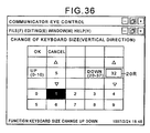
- Fig. 36 is a diagram showing a screen for changing the size of the keyboard in the vertical direction.
- the screen in Fig. 36 is displayed.
- the third numeral from the top in the second column from the left is the margin between the lower edge of the menu bar of a window provided by Windows95 (Microsoft Corp.) and the upper edge of the keyboard.
- the third numeral from the top in the fifth column from the left is the distance between the lower edge of the menu bar and the lower edge of the keyboard (assuming this numeral is A, the margin between the upper edge of the input character display portion and the lower edge of the keyboard is represented as 37 - A).
- a numeral is changed by selecting an arrow above or below the numeral.
- a numeral is selected (a red frame 20R is displayed when it is selected) and an option of "0" to "9” is selected to directly input the numeral. The numeral is determined and the "OK" cell is selected to confirm the setup.
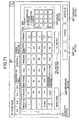
- Fig. 37 is a diagram showing the character selection screen after the size of the keyboard has been changed.
- This character selection screen is provided by selecting the numerals in the horizontal direction and in the vertical direction as left, 5, and right, 59, and up, 5, and down, 32.
- the setting of the numerals "1" in the vertical and in the horizontal direction is equivalent to a change of 10 dots on the screen.
- Fig. 38 is a diagram showing a screen for changing the setup when determining whether the cursor should be moved to a visual axis position when the visual axis is positioned on the sentence display portion on the character selection screen.
- the visual axis is positioned at an arbitrary location in the sentence display portion on the character selection screen.
- the cursor can be moved to the visual axis position.
- Fig. 39 is a diagram showing a screen for printing a sentence that has been created. Whether a sheet of paper will be discharged can be set by selecting "Yes” or “No” on this screen. This is effective when printing short sentences.
- "No” paper need not be fully discharged from the printer each time printing occurs; only the portion that has been printed is fed out of the printer, and the paper discharge function of the printer is halted to permit a third party to read the printed portion. Since the next printing is initiated at the point the discharge of paper is halted, paper can be saved.
- Fig. 40 is a diagram showing a registration screen for storing in a memory a sentence that has been created. With this screen, the user can register and store at an arbitrary location a sentence created on the character selection screen. The registration screen is displayed by selecting "Registration" on the character selection screen.
- the topmost function keys are keys for registration options, and the second through the fifth rows are registered sentence display portions.
- the page of a registered sentence is displayed in the bottom row of the display portion.
- a maximum of eight sentences can be registered for one registered sentence page. Since there are 10 registered sentence pages, a total of 80 sentences can be registered.
- a sentence created on the character selection screen is displayed directly below the option display portion, and a description the effect on this sentence of the registration function keys in the topmost row will be given first.
- Fig. 41 is a diagram of the screen on which the results of sentence registration are shown.
- the sentences "Good afternoon” and "How are you?" are respectively moved from the first and the second rows in the registered sentence display portion to the second and the third rows, and a sentence "It is a fine day today, isn't it?", which was created on the character selection screen is registered and is inserted into the first row of the registered sentence display portion.
- Delete Deletes a sentence at a currently selected registered sentence display position (the first row, enclosed by the red frame 30R in the registered sentence display portion in Fig. 40).
- Fig. 42 is a diagram showing a screen for confirming the intent of the user in response to the selection of "Delete”.
- Fig. 43 is a diagram showing a screen for displaying the results of the deletion. It should, however, be noted, that when in Fig. 43 "Cancel" is entered in the registration mode, the deletion of the entry is not final, and the screen is returned to the character selection screen.
- confirmation of the intent of the user is effected.
- Fig. 44 is a diagram showing a screen for confirming the intent of the user when "All delete” is entered. When “Yes” is selected, all the entries are deleted. It should be noted, however, that when "Cancel” is entered in the registration mode, the deletion of all entries is not final, and the screen is returned to the character selection screen.
- the registered sentences are managed in a TXT file when the application is not in use, and are managed in a registered sentence control arrangement when the application is in use.
- the registered sentence control arrangement is two-dimensional, with the first element number being represented using the registered sentence page, and the second element number indicating the position among the ten sentences on each registered sentence page.
- Fig. 47 is a flowchart showing the reading processing, when the application is activated, for a TXT file in which registered sentences are written.
- a file in which registered sentences are written is opened (step S1302).
- all the registered sentences are read, as a single sentence string, from the file in which they are written (step S1303).
- Fig. 48 is a diagram showing the string in a file where the registered sentences are written. A registered sentence string is divided using a return code ( ⁇ n), and from the beginning, the separate sentences are written, in order, into the registered sentence control arrangement (step S1304).
- Fig. 49 is a flowchart showing the processing for writing a registered sentence to a TXT file when an application is terminated. All the sentences in the registered sentence control arrangement are converted into a sentence string (step S1307). Then the obtained sentence string (see Fig. 48) is written into the registered sentence TXT file (step S1308). The TXT file is then closed (step S1309).
- Fig. 50 is a diagram showing a call screen for retrieving registered sentences and inserting them into the sentence display portion on the character selection screen. With this function, the user can retrieve a registered sentence and insert it into a desired position in the sentence display portion on the character selection screen.
- the call screen is displayed by selecting "Call" on the character selection screen.
- the topmost row are displayed function keys relative to call, and the second to the fifth rows are a called sentence display portion.
- the bottommost row displays the page of the called sentences.
- Two types of sentences are called: a registered sentence that is created by the user and is registered in the registration mode, and a common fixed sentence that is employed daily and is supplied as part of in the application.
- a total of 80 fixed sentences are prepared for 10 pages in addition to the previously mentioned registered sentences.
- a sentence when selected and called is displayed below the option display portion.
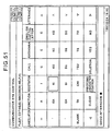
- Fig. 51 is a diagram showing a screen reflecting the result of a call. In the created sentence, "Good afternoon” has been called.
- “Cancel” Cancels a call and the insertion of a selected sentence into a sentence that has been created on the character selection screen, and then terminates the call mode.
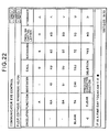
- Fig. 52 is a table showing the fixed sentences and the names of the fixed sentence pages.
- Utterance Utters a currently selected sentence.
- the user can hold a conversation by repeating the selection and the utterance of a called sentence in the call mode, without each time retrieving the sentence into the sentence display portion on the character selection screen.
- Fig. 53 is a diagram showing a screen wherein the first through the fourth sentences on the first fixed sentence page are displayed in the called sentence display portion. When " ⁇ " is selected, the fifth to the eighth sentences on the first fixed sentence page are displayed in the called sentence display portion.
- Fig. 54 is a diagram showing a screen wherein the mark " ⁇ " has been is changed to " ⁇ ".
- the called sentence page display portion at the lowermost row will be explained.
- the processing for this is the same as that for the registered sentence pages.
- the fixed sentence pages are displayed in the called sentence display portion, and the names of the fixed sentence pages are as shown in Fig. 52.
- the registered sentence pages are displayed in the called sentence page display portion, and the names of the registered sentence pages that are displayed are "P.1" to "P.10,” as was previously described.
- the "Change input confirmation method" function on the function selection screen 2 may switch the method for establishing an entry when the visual axis position is held on the same option for a predetermined period of time or longer, the method for establishing an entry for which a user looks at the same choice and then closes the eyes for a predetermined period of time, and the method for establishing an entry for which a user stares at the same character and then depresses a switch for a predetermined period of time.
- a user can select an option by moving his, or her, eyes. Therefore, it is easy for a seriously physically handicapped person who can not depress a foot button to establish which character is to be input.
- the user can correctly enter a choice by moving his, or her, eyes.
- the display panel video is projected on a screen, imposing an excessive load on the eyes when selecting an option can be prevented.
- the display panel video is projected on the screen, the load applied on the eyes when selecting an option can be reduced, and a user can select a correct option choice by moving his, or her, eyes even when the position of the head is changed.
- a user can enter a character simply by viewing the video.
- the load imposed on the eyes can be reduced, compared with when to select an option the position of the visual axis is sustained for a specific period of time.
- a user can select an option by moving his, or her, eyes, and using a slight body movement to confirm the selection.
- a visual axis entry transmission apparatus that provides on a computer screen a display panel consisting of a plurality of characters, such as hiragana or alphabetical characters, detects the visual axis of a user who is viewing the display panel, employs the result of the detection of the visual axis of the user to identify a character the user selects, and accepts the identified character.
- a visual axis entry transmission apparatus that can switch television channels, and a visual axis entry transmission apparatus with which the user, while monitoring a computer screen, can exchange a display panel video image displayed on the computer screen for one that is input to the computer.
- a method for the visual axis entry transmission apparatus, a method is employed for verifying a selected character whereby a user by looking at the character and closing his, or her, eyes. This method, closing one's eyes, for verifying an entry is also employed when instructing a television channel change.
- the apparatus does not include means for notifying a user of the frequent occurrences of visual axis detection errors, such as input errors that are caused by the eyes being closed too early or visual axis detection failures that occur when the eyes of a user are incorrectly captured, when such detection errors occur there is no means by which a user can be notified. As a result, a user who is unaware of the operating conditions may input a useless operation.
- the display areas for the options are reduced and it is difficult to select a desired choice.
- a visual axis entry transmission apparatus that resolves the above shortcomings will now be described according to an eleventh through a twenty-first embodiment of the present invention.
- the personal computer 1008 in Fig. 5 performs a video display process, for supplying video data to be viewed by a user to the liquid crystal display circuit 1007 in the head-mounted display unit 1006, and an option input process, for acquiring through the accessory device controller 1815 focusing point data that are obtained by the visual axis detection circuit 1064 of the head-mounted display unit 1006; and for employing the focusing point data to identify and enter an option that is selected from among those displayed in the video image on the liquid crystal display device 1002.
- a detection result notification process for the operating condition can be performed whereby focusing point data are employed to determine whether or not the detection of the visual axis was successful, whether the user's eyes are blinking, or whether the same choice has been selected; and whereby, in accordance with the result obtained by the determination, information concerning the detected condition can be provided to the user.
- this detection result notification process is selected by the user, in this embodiment the user is provided detection result information by changing the selection frame colors for options displayed in the video image that the user is viewing.
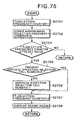
- Figs. 55 and 56 are flowcharts showing the visual axis detection result information notification processing performed by the visual axis entry transmission apparatus in Fig. 3.
- step S101 visual axis position data that are obtained by the visual axis detection circuit 1064 of the head-mounted display unit 1006 are employed to determine whether the user's eyes were kept closed.
- program control moves to step S102, whereat counter EyeBlinkCnt for measuring the time period during which the user's eyes were closed is reset.
- step S103 a character at the visual axis position is acquired as a selected character based on the visual axis position data that were obtained by the visual axis detection circuit 1064.
- step S104 a check is performed to determine whether the currently selected character is the same as a preceding character that was selected.
- step S107 When the two characters are the same, program control moves to step S107, whereat the value at counter SelectedCnt, which is an up-counter, is incremented by one. Program control then goes to step S114 in Fig. 56. If the currently selected character is not the same as the previously selected character, program control moves to step S105, whereat data for the selected character are updated to those for the currently selected character. Then, at step S106, the counter SelectedCnt is reset, and program control goes to step S114.
- step S108 When at step S101 the user's eyes were kept closed, at step S108 whether or not the closing of the eyes was a blink is determined, based on whether detection data that indicate blinking were received from the visual axis detection circuit 1064. If the closing of the eyes was a blink, at step S109 flag EyeBlinkStartFlg is set to "1", and program control advances to step S110. When at step S108 the closing of the eyes was not a blink, program control skips step S109 and goes to step S110, whereat the value at the counter EyeBlinkCnt for measuring the time the eyes are closed is incremented by one.
- step S111 a check is performed to determine whether the count value of the counter EyeBlinkCnt is equal to or greater than a preset value.
- program control goes to step S114 in Fig. 56.
- step S112 When the count value of the counter EyeBlinkCnt is equal to or greater than the preset value, at step S112 a check is performed to determine whether the count value of the counter SelectedCnt is equal to or greater than a preset value.
- the preset value for the counter SelectedCnt differs from that for the counter EyeBlinkCnt.
- program control moves to step S114 in Fig. 56.
- the count value of the counter SelectedCnt is equal to or greater than the preset value, it is assumed that the values of the counter EyeBlinkCnt and the counter SelectedCnt satisfy the corresponding preset values and that a character input condition has been established.
- Program control then moves to step S113, whereat the processing is advanced to the character input processing.
- step S114 a check is performed to determine whether the visual axis detection result condition display mode has been set. When the visual axis detection result condition display mode has not been set, program control exits this processing sequence. When the visual axis detection result condition display mode has been set, at step S116 a check is performed to determine whether the count value of the counter EyeBlinkCnt and the value of the flag EyeBlinkStartFlg satisfy the values that are specified under the first condition.
- step S118 a check is performed to determine whether the count value of the counter EyeBlinkCnt, the value of the flag EyeBlinkStartFlg and the count value of the counter SelectedCnt satisfy the values that are specified under the second condition.
- this means that it has been established that the count value of the counter EyeBlinkcnt ⁇ 1, that the value of the flag EyeBlinkStartFlg 1, and that the count value of the counter SelectedCnt ⁇ the preset value.
- step S119 the color of a selection frame for the corresponding option in the video image on the liquid crystal display device 1002 that the user is viewing is changed to a color indicating that the entry of a selected character has not yet been established.
- Program control thereafter exits this processing sequence.
- brown is the color used to indicate that the entry of a selected character has not been established.
- step S120 a check is performed to determine whether the count value of the counter EyeBlinkCnt, the value of the flag EyeBlinkStartFlg and the count value of the counter SelectedCnt satisfy the values that are specified under the third condition.
- this means it has been established that the count value of the counter EyeBlinkCnt ⁇ 1, that the value of the flag EyeBlinkStartFlg 1, and that the count value of the counter SelectedCnt ⁇ the preset value.
- the third condition i.e., when the count value of the counter SelectedCnt equals the preset value, it is assumed that the selection of the character was established by the eyes being kept closed for a predetermined period of time because, while the selected character was confirmed, the count value of the counter EyeBlinkCnt was equal to or greater than "1" and the value of the flag EyeBlinkStartFlg was "1".
- the color of a selection frame for the corresponding choice in the video image on the liquid crystal display device 1002 that the user is viewing is changed to a color indicating that the entry of a selected character was effected by the eyes being kept closed for a predetermined period of time.
- Program control thereafter exits this processing sequence.
- green is used to indicate that the entry of a selected character was effected by the eyes being closed for a predetermined period of time.
- step S122 a check is performed to determine whether the count value of the counter SelectedCnt satisfies the value that is specified under the fourth condition.
- the count value satisfies the fourth condition this means that it has been established that the count value of the counter SelectedCnt ⁇ the preset value.
- the fourth condition i.e., when the count value of the counter SelectedCnt has equaled the preset value, it is assumed that the user's eyes were not closed because, although the selected character has been confirmed, the current condition does not correspond to the first through the third conditions.
- step S123 the color of a selection frame for the corresponding option in the video image on the liquid crystal display device 1002 that the user is viewing is changed to a color indicating that a character has been confirmed.
- Program control thereafter exits this processing sequence.
- blue is used to indicate that a character has been confirmed.
- the fourth condition i.e., when the condition does not correspond to the first to the fourth condition, it is assumed that the user's eyes are open and a character has not yet been selected because it has been established that the count value of the counter SelectedCnt ⁇ the preset value. Then, at step S124, the color of a selection frame for the corresponding option in the video image on the liquid crystal display device 1002 that the user is viewing is changed to a color indicating that no character has been selected. Program control thereafter exits this processing. In this embodiment, yellow is used to indicate that no character has been selected.
- the user is provided detection result information by changing the color of the selection frame for a selectable character in the video image that the user is viewing. Therefore, the user can confirm the result of the detection of the visual axis, and the possibility that the user will repeat a useless operation can be eliminated.
- the user is provided detection result information by changing the color of the selection frame for a selectable character in the video image that the user is viewing; however, the color of a selected character or the background of a selected character may also be changed to provide detection result information for the user.
- the selection of characters is employed, but the same system that is used to provide a user the visual axis detection result can be employed to make a selection consisting of a figure other than a character.
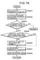
- FIG. 57 and 58 are flowcharts showing the visual axis detection result information notification processing performed by the visual axis entry transmission apparatus according to the twelfth embodiment.
- the arrangement for this embodiment is the same as that for the eleventh embodiment, except that a user is notified of detection result information by receiving an audio message that is generated through a loudspeaker incorporated in a personal computer 1008. Therefore, no explanation for the arrangement will be given.
- step S2201 visual axis position data that are obtained by the visual axis detection circuit 1064 of the head-mounted display unit 1006 are employed to determine whether the user keeps the eyes closed.
- program control moves to step S2202, whereat counter EyeBlinkCnt is reset.
- step S2203 a character at the visual axis position is obtained as a selected character based on the visual axis position data that are obtained by the visual axis detection circuit 1064.
- step S2204 a check is performed to determine whether the currently selected character is the same as a preceding character that was selected.
- step S2207 When the two characters are the same, program control moves to step S2207, whereat the value at counter SelectedCnt is incremented by one. Program control then goes to step S2214 in Fig. 58. If the currently selected character is not the same as the previously selected character, program control moves to step S2205, whereat data for the selected character are updated to those for the currently selected character. Then, at step S2206 the counter SelectedCnt is reset, and program control goes to step S2214.
- step S2208 determines whether the closing of the eyes is a blink is determined depending on whether detection data that indicate blinking are received from the visual axis detection circuit 1064. If the closing of the eyes is a blink, at step S2209 flag EyeBlinkStartFlg is set to "1", and program control advances to step S2210. When at step S2208 the closing of the eyes is not a blink, program control skips step S2209 and goes to step S2210, whereat the value at the counter EyeBlinkCnt is incremented by one. Sequentially, at step S2211 a check is performed to determine whether the count value of the counter EyeBlinkCnt is equal to or greater than a preset value. When the count value of the counter EyeBlinkCnt is not equal to or greater than the preset value, program control goes to step S2214 in Fig. 58.
- step S2212 a check is performed to determine the count value of the counter SelectedCnt is equal to or greater than a preset value.
- the preset value for the counter SelectedCnt differs from that for the counter EyeBlinkCnt.
- program control moves to step S2214 in Fig. 58.
- the count value of the counter SelectedCnt is equal to or greater than the preset value, it is assumed that the values of the counter EyeBlinkCnt and the counter SelectedCnt satisfy the corresponding preset values and that the character input condition is established.
- Program control then moves to step S2213, whereat the processing is moved to the character input processing.
- step S2214 a check is performed to determine whether the visual axis detection result condition display mode is set. When the visual axis detection result condition display mode is not set, program control exits from this processing sequence.
- step S2216 a check is performed to determine whether the count value of the counter EyeBlinkCnt and the value of the flag EyeBlinkStartFlg satisfy the values that are specified under the first condition.
- step S2218 a check is performed to determine whether the count value of the counter EyeBlinkCnt, the value of the flag EyeBlinkStartFlg and the count value of the counter SelectedCnt satisfy the values that are specified under the second condition.
- this means that the count value of the counter EyeBlinkCnt ⁇ 1, the value of the flag EyeBlinkStartFlg 1 and the count value of the counter SelectedCnt ⁇ the preset value are established.
- step S2220 a check is performed to determine whether the count value of the counter EyeBlinkCnt, the value of the flag EyeBlinkStartFlg and the count value of the counter SelectedCnt satisfy the values that are specified under the third condition.
- this means that the count value of the counter EyeBlinkCnt ⁇ 1, the value of the flag EyeBlinkStartFlg 1 and the count value of the counter SelectedCnt ⁇ the preset value are established.
- step S2222 a check is performed to determine whether the count value of the counter SelectedCnt satisfies the value that is specified under the fourth condition. When the count value satisfies the fourth condition, this means that the count value of the counter SelectedCnt ⁇ the preset value is established.
- the fourth condition i.e., when the count value of the counter SelectedCnt has reached the preset value, it is assumed that the eyes are not closed because the selected character is confirmed but the current condition does not correspond to the first to the third condition.
- a vocal message indicating that the selected character is confirmed is stored in a vocal output memory.
- step S2225 a vocal output process is performed to release the vocal message stored in the vocal output memory. Program control thereafter exists this processing sequence.
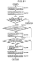
- FIGS. 59 and 60 are flowcharts showing the visual axis detection result information notification processing performed by the visual axis entry transmission apparatus according to the thirteenth embodiment.
- the arrangement for this embodiment is the same as that for the eleventh embodiment, except that a user is notified of detection result information by receiving a beep sound that is released through a loudspeaker incorporated in a personal computer 1008. Therefore, no explanation for the arrangement will be given.
- step S2314 a check is performed to determine whether the visual axis detection result condition display mode is set. When the visual axis detection result condition display mode is not set, program control exits from this processing sequence.
- step S2316 a check is performed to determine whether the count value of the counter EyeBlinkCnt and the value of the flag EyeBlinkStartFlg satisfy the values that are specified under the first condition.
- step S2318 a check is performed to determine whether the count value of the counter EyeBlinkCnt, the value of the flag EyeBlinkStartFlg and the count value of the counter SelectedCnt satisfy the values that are specified under the second condition.
- this means that the count value of the counter EyeBlinkCnt ⁇ 1, the value of the flag EyeBlinkStartFlg 1 and the count value of the counter SelectedCnt ⁇ the preset value are established.
- step S2320 a check is performed to determine whether the count value of the counter EyeBlinkCnt, the value of the flag EyeBlinkStartFlg and the count value of the counter SelectedCnt satisfy the values that are specified under the third condition.
- this means that the count value of the counter EyeBlinkcnt ⁇ 1, the value of the flag EyeBlinkStartFlg 1 and the count value of the counter SelectedCnt ⁇ the preset value are established.
- step S2322 a check is performed to determine whether the count value of the counter SelectedCnt satisfies the value that is specified under the fourth condition.
- the count value satisfies the fourth condition this means that the count value of the counter SelectedCnt ⁇ the preset value is established.
- the fourth condition i.e., when the count value of the counter SelectedCnt has reached the preset value, it is assumed that the eyes are not closed because the selected character is confirmed but the current condition does not correspond to the first to the third condition.
- beep sound data indicating that the selected character is confirmed is stored in a vocal output memory.
- step S2325 a vocal output process is performed to release the beep sound data stored in the vocal output memory. Program control thereafter exists this processing sequence.
- FIG. 60 and 61 are flowcharts showing the visual axis detection result information notification processing performed by the visual axis entry transmission apparatus according to the fourteenth embodiment.
- the arrangement for this embodiment is the same as that for the eleventh embodiment, except that a plurality of light emitting diodes (not shown) are incorporated in a head-mounted display unit 1006 and a user is notified of detection result information by controlling light emitted by these diodes. Therefore, no explanation for the arrangement will be given.
- the visual axis detection result information notification processing will now be described while referring to Figs. 61 and 62. Since this processing differs from the processing in the twelfth embodiment only in that to send a notification the ON states of a plurality of light emitting diodes, which emit visible light, are employed instead of the vocal message, only the portion that differs will be explained. Furthermore, since the processing at steps S2401 to S2413 in Fig. 61 is the same as that at steps S2201 to S2213 in the twelfth embodiment, no explanation for it will be given.
- step S2414 a check is performed to determine whether the visual axis detection result condition display mode is set. When the visual axis detection result condition display mode is not set, program control exits from this processing.
- step S2416 a check is performed to determine whether the count value of the counter EyeBlinkCnt and the value of the flag EyeBlinkStartFlg satisfy the values that are specified under the first condition.
- step S2425 the ON command is output to the light emitting diode LED1 by the I/F output memory, and program control thereafter exits this processing sequence.
- the light emitting diode LED1 is turned on to notify the user that no blinking was detected while the eyes were closed.
- step S2418 a check is performed to determine whether the count value of the counter EyeBlinkCnt, the value of the flag EyeBlinkStartFlg and the count value of the counter SelectedCnt satisfy the values that are specified under the second condition.
- this means that the count value of the counter EyeBlinkCnt ⁇ 1, the value of the flag EyeBlinkStartFlg 1 and the count value of the counter SelectedCnt ⁇ the preset value are established.
- step S2419 an ON command for a light emitting diode LED2 indicating that the entry of the selected character is not yet established is stored in an I/F output memory.
- step S2425 the ON command is output to the light emitting diode LED2 by the I/F output memory, and program control thereafter exits this processing sequence.
- the light emitting diode LED2 is turned on to notify the user that the entry of the selected character is not yet established.
- step S2420 a check is performed to determine whether the count value of the counter EyeBlinkCnt, the value of the flag EyeBlinkStartFlg and the count value of the counter SelectedCnt satisfy the values that are specified under the third condition.
- this means that the count value of the counter EyeBlinkCnt ⁇ 1, the value of the flag EyeBlinkStartFlg 1 and the count value of the counter SelectedCnt ⁇ the preset value are established.
- the third condition i.e., when the count value of the counter SelectedCnt has reached the preset value, it is assumed that the selected character can be established by keeping the eyes closed for a predetermined period of time because, while the selected character is confirmed, the count value of the counter EyeBlinkCnt is equal to or greater than "1" and the value of the flag EyeBlinkStartFlg is "1". Then, at step S2421 an ON command for a light emitting diode LED3 indicating that the selected character can be established by keeping the eyes closed for a predetermined period of time is stored in an I/F output memory.
- step S2425 the ON command is output to the light emitting diode LED3 by the I/F output memory, and program control thereafter exits this processing sequence.
- the light emitting diode LED3 is turned on to notify the user that the selected character can be established by keeping the eyes closed for a predetermined period of time.
- a check is performed to determine whether the count value of the counter SelectedCnt satisfies the value that is specified under the fourth condition.
- the count value satisfies the fourth condition this means that the count value of the counter SelectedCnt ⁇ the preset value is established.
- the fourth condition i.e., when the count value of the counter SelectedCnt has reached the preset value, it is assumed that the eyes are not closed because the selected character is confirmed but the current condition does not correspond to the first to the third condition.
- an ON command for a light emitting diode LED4 indicating that the selected character is confirmed is stored in an I/F output memory.
- step S2425 the ON command is output to the light emitting diode LED4 by the I/F output memory, and program control thereafter exits this processing sequence.
- the light emitting diode LED4 is turned on to notify the user that the selected character is confirmed.
- step S2424 an ON command for a light emitting diode LED5 indicating that a character is not yet selected is stored in an I/F output memory.
- the ON command is output to the light emitting diode LED5 by the I/F output memory, and program control thereafter exits this processing sequence.
- the light emitting diode LED5 is turned on to notify the user that a character is not yet selected.
- FIG. 63 is a flowchart showing external video display processing performed by a visual axis entry transmission apparatus according to the fifteenth embodiment of the present invention
- Figs. 64 and 65 are diagrams showing example screens displayed on the head-mounted display unit 1006 via the external video display processing in Fig. 63.
- the personal computer 1008 includes an interface for receiving an external video, and performs a display process whereby the received external video and the display panel, on which are displayed available choices by the visual axis input, are arranged together on the liquid crystal display device 1002 of the head-mounted display unit 1006; and a process, based on an instruction from the user, for setting an arbitrary display area ratio of the external video image to the display panel that are displayed on the liquid crystal display device 1002 of the head-mounted display unit 1006.
- step S501 a check is performed to determine whether an external video image is to be displayed.
- step S502 a variable that indicates the display area ratio of the external video to the display panel on liquid crystal display device 1002 is changed to a value that is applicable when only the display panel is displayed on the screen.
- Program control then goes to step S506, whereat choices are displayed on the display panel. Program control thereafter exits this processing sequence.
- step S501 When at step S501 the external video image is to be displayed, at step S503 a variable that represents the display area ratio of the external video image to the display panel on the liquid crystal display device 1002 is set to a desired value.
- step S504 the display size of the external video image is determined based on the ratio set at step S503.
- step S505 the control for the liquid crystal display circuit 1007 is initiated to display the external video image on the liquid crystal display device 1002.
- step S506 options are displayed in an area other than the display area for the external video image. Program control thereafter exits this processing sequence.
- the screen shown in Fig. 64 can be provided for the user.
- the "Scene, large” icon is selected by the entry of the visual axis.
- the external video image is enlarged and displayed using the entire display area of the liquid crystal display device 1002.
- the options are not displayed and only an icon (a round button at the right upper corner of the screen) for returning to the screen shown in Fig. 64 is displayed.
- the user can monitor the external video image as well as the options.
- FIGs. 66 to 68 are diagrams showing example screens displayed on the head-mounted display unit 1006 via the video display processing performed by a visual axis entry transmission apparatus according to the sixteenth embodiment of the present invention.
- the personal computer 1008 includes an interface for receiving an external video image, and performs a display process for overlapping options, on the screen of the liquid crystal display device 1002 of the head-mounted display unit 1006, that can be selected by moving the visual axis to their screen locations. In addition, whether the external video image and the options are to be displayed overlapping can be selected. Furthermore, a process is performed whereby, when a specific portion of the external video image is selected by moving the visual axis to the location the portion occupies on the screen on which only the external video image is displayed, whether the portion is in an option display screen location is determined, and whereby, when the portion to which the visual axis is moved is in an option display screen location the corresponding option for that location is displayed overlapping the external video image.
- the external video image and the options can be displayed overlapping each other, as is shown in Fig. 66.
- the user can select an option by using the visual axis while monitoring the externally input video image.
- FIGs. 69 to 72 are diagrams showing example screens displayed on the head-mounted display unit 1006 via the video image display processing performed by a visual axis entry transmission apparatus according to the seventeenth embodiment of the present invention.
- the display form for an option is changed and the option is displayed in its new form on the liquid crystal display device 1002 of the head-mounted display unit 1006.
- the "Set” menu option is selected and the menu screen in Fig. 70 is opened.
- the "Set scene color” menu item is selected on this screen, the "Set scene color” dialogue box in Fig. 71 is opened, a specific scene is selected in the dialogue box using a scene selection tag 221, and a color change target option is instructed by a selection button 222.
- a background color/character color check button 223 is used to instruct a background color change or a character color change in the "Set color” portion, and a color button 224 is employed to designate a desired color.
- a "MemoPage” button 225 is selected. Then, the background color change or the character color change in the "Set color” portion is instructed by using the background color/character color check button 223, and a desired color is selected by using the color button 224. Finally, the selection button 222 is employed.
- a "Select all” button 226 is used to display in one color all the options and the memopage display portion on the selection screen. Then, the background color change or the character color change is instructed by using the background color/character color check button 223, and a desired color is selected by using the color button 224.
- an "Update” button 227 in the lower portion of the dialogue box is selected, so that the options are displayed in a different color on the head-mounted display unit 1006.
- an "OK" button 228 is selected instead of the "Update” button 227 and the "Set scene color” dialogue box is closed, the option colors can be changed on the head-mounted display unit 1006.
- the screen in Fig. 72 is displayed on the head-mounted display unit 1006.
- the options can be so displayed that the user can easily identify them.
- Fig. 73 is a diagram showing an example selection screen displayed on the head-mounted display unit 1006 via the selection processing performed by a visual axis entry transmission apparatus according to the eighteenth embodiment of the present invention.
- Fig. 74 is a flowchart showing the selection processing performed by the visual axis entry transmission apparatus according to the eighteenth embodiment.
- Fig. 75 is a flowchart showing up arrow key selection processing at step S1602 in Fig. 74.
- Fig. 76 is a flowchart showing down arrow key selection processing at step S1604 in Fig. 74.
- Fig. 73 is a diagram showing an example selection screen displayed on the head-mounted display unit 1006 via the selection processing performed by a visual axis entry transmission apparatus according to the eighteenth embodiment of the present invention.
- Fig. 74 is a flowchart showing the selection processing performed by the visual axis entry transmission apparatus according to the eighteenth embodiment.
- Fig. 75 is a flowchart showing
- 77 is a flowchart showing right arrow key selection processing at step S1606 in Fig. 74.
- Fig. 78 is a flowchart showing left arrow key selection processing at step S1608 in Fig. 74.
- Fig. 79 is a flowchart showing up-left arrow key selection processing at step S1610 in Fig. 74.
- Fig. 80 is a flowchart showing up-right arrow key selection processing at step S1612 in Fig. 74.
- Fig. 81 is a flowchart showing down-left arrow key selection processing at step S1614 in Fig. 74.
- Fig. 82 is a flowchart showing down-right arrow key selection processing at step S1616 in Fig. 74.
- options are selected by performing visual axis entries a plurality of times. Specifically, as is shown in Fig. 73, options are positioned in the center of the selection screen, and " ⁇ ", “ ⁇ ”, “ ⁇ ”, “ ⁇ ”, “ ⁇ ”, “ ⁇ ” and “ ⁇ ” arrows are positioned around the periphery.
- the user selects one of the eight arrow keys by moving the visual axis to the screen location occupied by the key and performing the visual axis entry that satisfies the visual axis confirmation condition. Then, the character or the option inside the selection frame is selected and entered.
- step S1601 a check is performed to determine whether the visual axis is positioned at the " ⁇ " key on the selection screen displayed on the head-mounted display unit 1006.
- step S1602 program control moves to step S1602, whereat the up arrow key selection processing is performed.
- step S1603 program control moves to step S1603 and a check is performed to determine whether the visual axis is positioned at the " " key on the selection screen.
- step S1604 program control moves to step S1604, whereat the down arrow key selection processing is performed.
- step S1605 When the visual axis is not positioned at the " " key, program control moves to step S1605 and a check is performed to determine whether the visual axis is positioned at the " ⁇ " key on the selection screen.
- step S1606 When the visual axis is positioned at the " ⁇ ” key, program control moves to step S1606, whereat the right arrow key selection processing is performed.
- step S1607 When the visual axis is not positioned at the " ⁇ ” key, program control moves to step S1607 and a check is performed to determine whether the visual axis is positioned at the " ⁇ " key on the selection screen.
- step S1608 When the visual axis is positioned at the " ⁇ ” key, program control moves to step S1608, whereat the left arrow key selection processing is performed.
- step S1609 When the visual axis is not positioned at the " ⁇ " key, program control moves to step S1609 and a check is performed to determine whether the visual axis is positioned at the " ⁇ " key on the selection screen.
- step S1610 When the visual axis is positioned at the " ⁇ ” key, program control moves to step S1610, whereat the up-left arrow key selection processing is performed.
- step S1611 When the visual axis is not positioned at the " ⁇ ” key, program control moves to step S1611 and a check is performed to determine whether the visual axis is positioned at the " ⁇ " key on the selection screen.
- step S1612 When the visual axis is positioned at the " ⁇ ” key, program control moves to step S1612, whereat the up-right arrow key selection processing is performed.
- step S1613 When the visual axis is not positioned at the " ⁇ " key, program control moves to step S1613 and a check is performed to determine whether the visual axis is positioned at the " ⁇ " key on the selection screen.
- step S1614 When the visual axis is positioned at the " ⁇ ” key, program control moves to step S1614, whereat the down-left arrow key selection processing is performed.
- step S1615 When the visual axis is not positioned at the " ⁇ ” key, program control moves to step S1615 and a check is performed to determine whether the visual axis is positioned at the " ⁇ " key on the selection screen.
- step S1616 When the visual axis is positioned at the " ⁇ ” key, program control moves to step S1616, whereat the down-right arrow key selection processing is performed.
- the visual axis is not positioned at the " ⁇ ” key, it is assumed that the visual axis is not positioned at any of the arrow keys, and program control thereafter exits this processing sequence
- step S2701 the value of an up arrow key selection frequency counter is incremented by one, and at step S2702 the other arrow key selection frequency counters are reset.
- step S2703 a check is performed to determine whether the count value of the up arrow key selection frequency counter is equal to or greater than a preset value. When the value of the up arrow selection frequency counter is smaller than the preset value, program control exits this processing sequence.
- step S2705 When the value of the up arrow selection frequency counter is equal to or greater than the preset value, at step S2705 a check is performed to determine whether the current vertical direction selection cell number is 0, i.e., whether the currently selected option is positioned at the topmost cell. If the currently selected choice is not located at the topmost cell, at step S2706 the vertical direction cell number is incremented by one, and program control advances to step S2707. When the currently selected option is located at the topmost cell, program control skips step S2706 and goes to step S2707.
- step S2707 the up arrow selection frequency counter is reset, and at step S2708 the screen is again displayed. Program control thereafter exits this processing sequence.
- step S2801 the value of a down arrow key selection frequency counter is incremented by one, and at step S2802 the other arrow key selection frequency counters are reset.
- step S2803 a check is performed to determine whether the count value of the down arrow key selection frequency counter is equal to or greater than a preset value. When the value of the down arrow selection frequency counter is smaller than the preset value, program control exits this processing sequence.
- step S2805 When the value of the down arrow selection frequency counter is equal to or greater than the preset value, at step S2805 a check is performed to determine whether the current vertical direction selection cell number is a maximum value, i.e., whether the currently selected option is positioned at the lowermost cell. If the currently selected choice is not located at the lowermost cell, at step S2806 the vertical direction cell number is decremented by one, and program control advances to step S2807. When the currently selected option is located at the lowermost cell, program control skips step S2806 and goes to step S2807.
- step S2807 the down arrow selection frequency counter is reset, and at step S2808 the screen is again displayed. Program control thereafter exits this processing sequence.
- step S1901 the value of a right arrow key selection frequency counter is incremented by one, and at step S1902 the other arrow key selection frequency counters are reset.
- step S1903 a check is performed to determine whether the count value of the right arrow key selection frequency counter is equal to or greater than a preset value. When the value of the right arrow selection frequency counter is smaller than the preset value, program control exits this processing sequence.
- step S1905 When the value of the right arrow selection frequency counter is equal to or greater than the preset value, at step S1905 a check is performed to determine whether the current horizontal direction selection cell number is a maximum value, i.e., whether the currently selected option is positioned at the rightmost cell. If the currently selected choice is not located at the rightmost cell, at step S1906 the horizontal direction cell number is incremented by one, and program control advances to step S1907. When the currently selected option is located at the rightmost cell, program control skips step S1906 and goes to step S1907.
- step S1907 the right arrow selection frequency counter is reset, and at step S1908 the screen is again displayed. Program control thereafter exits this processing sequence.
- step S2001 the value of a left arrow key selection frequency counter is incremented by one, and at step S2002 the other arrow key selection frequency counters are reset.
- step S2003 a check is performed to determine whether the count value of the left arrow key selection frequency counter is equal to or greater than a preset value. When the value of the left arrow selection frequency counter is smaller than the preset value, program control exits this processing sequence.
- step S2005 a check is performed to determine whether the current horizontal direction selection cell number is 0, i.e., whether the currently selected option is positioned at the leftmost cell. If the currently selected choice is not located at the leftmost cell, at step S2006 the horizontal direction cell number is decremented by one, and program control advances to step S2007. When the currently selected option is located at the leftmost cell, program control skips step S2006 and goes to step S2007.
- step S2007 the left arrow selection frequency counter is reset, and at step S2008 the screen is again displayed. Program control thereafter exits this processing sequence.
- step S2101 the value of an up-left arrow key selection frequency counter is incremented by one, and at step S2102 the other arrow key selection frequency counters are reset.
- step S2103 a check is performed to determine whether the count value of the up-left arrow key selection frequency counter is equal to or greater than a preset value. When the value of the up-left arrow selection frequency counter is smaller than the preset value, program control exits this processing sequence.
- step S2105 When the value of the up-left arrow selection frequency counter is equal to or greater than the preset value, at step S2105 a check is performed to determine whether the current horizontal direction selection cell number is 0, i.e., whether the currently selected option is positioned at the leftmost cell. If the currently selected choice is not located at the leftmost cell, at step S2106 the horizontal direction cell number is decremented by one, and program control advances to step S2107. When the currently selected option is located at the leftmost cell, program control skips step S2106 and goes to step S2107.
- a check is performed to determine whether the current vertical direction selection cell number is 0, i.e., whether the currently selected option is positioned at the topmost cell. If the currently selected choice is not located at the topmost cell, at step S2108 the vertical direction cell number is incremented by one, and program control advances to step S2109. When the currently selected option is located at the topmost cell, program control skips step S2108 and goes to step S2109.
- step S2109 the up-left arrow selection frequency counter is reset, and at step S2110 the screen is again displayed. Program control thereafter exits this processing sequence.
- step S2201 the value of an up-right arrow key selection frequency counter is incremented by one, and at step S2202 the other arrow key selection frequency counters are reset.
- step S2203 a check is performed to determine whether the count value of the up-right arrow key selection frequency counter is equal to or greater than a preset value. When the value of the up-right arrow selection frequency counter is smaller than the preset value, program control exits this processing sequence.
- step S2205 When the value of the up-right arrow selection frequency counter is equal to or greater than the preset value, at step S2205 a check is performed to determine whether the current horizontal direction selection cell number is a maximum value, i.e., whether the currently selected option is positioned at the rightmost cell. If the currently selected choice is not located at the rightmost cell, at step S2206 the horizontal direction cell number is incremented by one, and program control advances to step S2207. When the currently selected option is located at the rightmost cell, program control skips step S2206 and goes to step S2207.
- a check is performed to determine whether the current vertical direction selection cell number is 0, i.e., whether the currently selected option is positioned at the topmost cell. If the currently selected choice is not located at the topmost cell, at step S2208 the vertical direction cell number is incremented by one, and program control advances to step S2209. When the currently selected option is located at the topmost cell, program control skips step S2208 and goes to step S2209.
- step S2209 the up-right arrow selection frequency counter is reset, and at step S2210 the screen is again displayed. Program control thereafter exits this processing sequence.
- step S2301 the value of a down-left arrow key selection frequency counter is incremented by one, and at step S2302 the other arrow key selection frequency counters are reset.
- step S2303 a check is performed to determine whether the count value of the down-left arrow key selection frequency counter is equal to or greater than a preset value. When the value of the down-left arrow selection frequency counter is smaller than the preset value, program control exits this processing sequence.
- step S2305 When the value of the down-left arrow selection frequency counter is equal to or greater than the preset value, at step S2305 a check is performed to determine whether the current horizontal direction selection cell number is 0, i.e., whether the currently selected option is positioned at the leftmost cell. If the currently selected choice is not located at the leftmost cell, at step S2306 the horizontal direction cell number is decremented by one, and program control advances to step S2307. When the currently selected option is located at the leftmost cell, program control skips step S2306 and goes to step S2307.
- a check is performed to determine whether the current vertical direction selection cell number is a maximum value, i.e., whether the currently selected option is positioned at the lowermost cell. If the currently selected choice is not located at the lowermost cell, at step S2308 the vertical direction cell number is incremented by one, and program control advances to step S2309. When the currently selected option is located at the lowermost cell, program control skips step S2308 and goes to step S2309.
- step S2309 the down-left arrow selection frequency counter is reset, and at step S2310 the screen is again displayed. Program control thereafter exits this processing sequence.
- step S2401 the value of a down-right arrow key selection frequency counter is incremented by one, and at step S2402 the other arrow key selection frequency counters are reset.
- step S2403 a check is performed to determine whether the count value of the down-right arrow key selection frequency counter is equal to or greater than a preset value. When the value of the down-right arrow selection frequency counter is smaller than the preset value, program control exits this processing sequence.
- step S2405 When the value of the down-right arrow selection frequency counter is equal to or greater than the preset value, at step S2405 a check is performed to determine whether the current horizontal direction selection cell number is a maximum value, i.e., whether the currently selected option is positioned at the rightmost cell. If the currently selected choice is not located at the rightmost cell, at step S2406 the horizontal direction cell number is incremented by one, and program control advances to step S2407. When the currently selected option is located at the rightmost cell, program control skips step S2406 and goes to step S2407.
- a check is performed to determine whether the current vertical direction selection cell number is a maximum value, i.e., whether the currently selected option is positioned at the lowermost cell. If the currently selected choice is not located at the lowermost cell, at step S2408 the vertical direction cell number is incremented by one, and program control advances to step S2409. When the currently selected option is located at the lowermost cell, program control skips step S2408 and goes to step S2409.
- step S2409 the down-right arrow selection frequency counter is reset, and at step S2410 the screen is again displayed. Program control thereafter exits this processing sequence.
- a selection frame can be moved to a desired character or option, and the visual axis entry that satisfies the visual axis input confirmation condition can be performed.
- the character or the option at the selection frame can be selected and entered, so that a specific entry can be performed easily and certainly, and the operating environment that facilities the data input can be provided for the user.
- FIGs. 83 and 84 are diagrams showing example selection screens that are displayed on the head-mounted display unit 1006 of a visual axis entry transmission apparatus according to the nineteenth embodiment of the present invention.
- Fig. 85 is a flowchart showing the processing performed by the visual axis entry transmission apparatus according to the nineteenth embodiment.
- the personal computer 1008 includes an interface for connecting an external device so that it can be controlled, and performs a process whereby available options are displayed on the head-mounted display unit 1006 to sequentially vary the degree of control provided for the external device, and whereby when one of the options is selected by shifting the visual axis, a command generated by the personal computer 1008 to sequentially vary the degree of control can be output through the interface to the external device.
- an external video image and options located around the periphery are displayed on the head-mounted display unit 1006.
- option "CH++” which instructs the sequential changing of the channels, one by one
- the personal computer 1008 sequentially outputs via the interface channel change commands to change the television channels one by one.
- the screen on the head-mounted display unit 1006 is changed to the screen shown in Fig. 84, on which an option is displayed to instruct at which channel the channel change sequence should be halted.
- "Discontinue" is selected by using the visual axis.
- the personal computer 1008 halts the output of the channel change command, so that the user can view the scene carried by the desired channel.
- step S3701 the visual axis detection process is performed.
- step S3702 a check is performed to determine whether the value of flag RmcnCntFlg, which indicates that a command is being sequentially output to the television, is "1.”
- the value of the flag RmcnCntFlg is "1," it is assumed that the command is being sequentially output to the television, and program control moves to step S3703.
- step S3703 the value of counter RmconCntiCnt, which serves as a timer for generating the output timing of the above command, is incremented by one.
- step S3704 a check is performed to determine whether the value of the counter RmconCntiCnt exceeds a preset value.
- program control advances to step S3705, whereat a process for outputting a command to advance the channel by one is performed.
- step S3706 the counter RmconCntiCnt is reset, and program control then goes to step S3707.
- program control skips steps S3705 and S3706 and moves to step S3707.
- step S3707 the visual axis entry process is performed.
- step S3708 a check is performed to determine whether the entry has been confirmed. When the entry has is been confirmed, program control exits this processing sequence.
- step S3710 a check is performed to determine the value of the flag RmcnCntFlg is 0. When the value of the flag RmcnCntFlg is 0, program control goes to step S3711, whereat the counter RmconCntiCnt is reset. Following this, at step S3712 a variable is changed for setting the display area ratio of the external video image to the option on the head-mounted display unit 1006.
- step S3713 the screen is again displayed based on the new variable setting, and program control thereafter exits this processing sequence.
- step S3713 the screen is again displayed based on the new variable setting, and program control thereafter exits this processing sequence.
- step S3714 the value of the flag RmcnCntFlg is not 0, program control moves to step S3714, whereat the input confirmation process is performed. Program control thereafter exits this processing sequence.
- step S3702 When, at step S3702, the value of the flag RmcnCntFlg is not 1, program control moves to step S3707, and the above described process is thereafter performed.
- the degree of control provided for the external device can be sequentially changed by employing the visual axis.
- control can also be provided for sequentially changing other functions, such as volume.
- FIGs. 86 and 87 are diagrams showing example selection screens displayed on the head-mounted display unit 1006 of a visual axis entry transmission apparatus according to the twentieth embodiment of the present invention.
- options are displayed as layers on the head-mounted display unit 1006.
- An option to be input is selected by employing the visual axis to trace in order the options that are located below an option that has been selected.
- options such as “A KA SA”, “TA NA HA” and “MA YA RA" are displayed on the first selection screen.
- a KA SA is an option that provides a group of hiragana characters in columns headed by “A”, “KA” and “SA”.
- TA NA HA is an option that provides a group of hiragana characters in columns headed by “TA”, “NA” and “HA”
- MA YA RA is a option that provides a group of hiragana characters in columns headed by "MA”, "YA” and "RA”.
- “Function” is a function for selecting, as a group, a remote control function, a hiragana/katakana/alphanumeric character mode switching function, a registration function, a fixed sentence calling function, and a setup change function.
- the screen is changed to another individual selection screen for the selection of individual options from the selected group. If a group of options is further included in the selected option group on the individual item selection screen, the user can sequentially trace options that are located below the selected option to select the individual option to be included in the group, and by employing the visual axis can display a pertinent selection screen.
- Options to be grouped under one option can be set arbitrarily. In this case, a process need only be performed whereby the options for forming a group are selected in advance in accordance with the instructions of a user, and the layers of the grouped options are traced in order.
- a plurality of options are grouped together under one option, that option is selected by selecting the options included therein, and a corresponding option is then selected from among the multiple options. That is, the visual axis is employed while the selection options located below the first selected option are traced in order, and a specific option is selected and established. Therefore, multiple selection options need not be displayed at one time, and the area for each option displayed can be larger than that when multiple options are displayed at the same time. As a result, the user can easily focus the visual axis on a desired option, and the occurrence of selection errors can be reduced.
- FIGs. 88 and 89 are diagrams showing example selection screens displayed on the head-mounted display unit 1006 of a visual axis entry transmission apparatus according to the twenty-first embodiment of the present invention.
- Fig. 88 words or phrases, such as “Yes”, “No” and “Thank you", are displayed that are frequently employed as responses. Therefore, as a response to a query by a user, "Yes” or “No” can be selected with one visual axis entry, and a quick response is possible, without an operation for sequentially inputting characters, such as "HA” and "I", being required.
- this selection screen can be employed as a screen for training in how to employ the visual axis for entries.
- the user can confirm the result of the detection of the visual axis, and does not have to uselessly repeat operations.
- the user can monitor an external video image while viewing the display panel.
- the user can view a screen having a desired display condition.
- the user can select an option by using the visual axis, while viewing an externally input video image.
- the options on the display panel can be displayed so that a user can easily identify them.
- the degree of control provided for an external device can be sequentially changed.
- the user can set a desired layer structure for options.
- the present invention can be applied to a system that is constituted by a plurality of devices, or to an apparatus that includes a single device.
- the present invention can also be applied by supplying a program to a system or to an apparatus.
- the effects of the present invention can be provided by adding to the system or to the apparatus a memory medium in which is stored a program that constitutes a software application for implementing the present invention.
- a ROM is employed as a memory medium.
- the memory medium is not limited to a ROM and can be, for example, a floppy disk, a hard disk, an optical disk, a magneto optical disk, a CD-ROM, a CD-R, a DVD, a magnetic tape or a nonvolatile memory card.
Landscapes
- Engineering & Computer Science (AREA)
- Theoretical Computer Science (AREA)
- General Engineering & Computer Science (AREA)
- Human Computer Interaction (AREA)
- Health & Medical Sciences (AREA)
- Heart & Thoracic Surgery (AREA)
- General Physics & Mathematics (AREA)
- Biomedical Technology (AREA)
- Physics & Mathematics (AREA)
- Vascular Medicine (AREA)
- Life Sciences & Earth Sciences (AREA)
- Animal Behavior & Ethology (AREA)
- General Health & Medical Sciences (AREA)
- Public Health (AREA)
- Veterinary Medicine (AREA)
- User Interface Of Digital Computer (AREA)
Claims (75)
- Blickrichtungseingabeübertragungsvorrichtung mit:einer Videoanzeigeeinrichtung zum Erzeugen einer Vielzahl von Icons zur Anzeige auf einem Anzeigefeld, wobei die Icons eine Vielzahl von Optionen für einen das Feld betrachtenden Benutzer darstellen;einer Blickrichtungserfassungseinrichtung (1064, 102) zum Erfassen der Blickrichtung eines ein Anzeigefeld ansehenden Benutzers; undeiner Bestimmungseinrichtung zum Bestimmen eines der Position der durch die Blickrichtungserfassungseinrichtung erfaßten Blickrichtung entsprechenden Icons;gekennzeichnet durch:eine Eingabeeinrichtung für ein externes Bild zum Empfangen eines externen Bildsignals; undeine Anzeigesteuereinrichtung, die der Videoanzeigeeinrichtung eine Anzeige eines externen Bilds gemäß dem externen Bildsignal ermöglicht, wobei die Anzeigesteuereinrichtung dann, wenn das externe Bild durch die Videoanzeigeeinrichtung angezeigt wird, dazu in der Lage ist, das externe Bildsignal und das durch die Blickrichtung des Benutzers bestimmte Icon einander überlagernd anzuzeigen.
- Vorrichtung nach Anspruch 1, mit:einer Kopfpositionserfassungseinrichtung (78) zum Erfassen der Kopfposition des Benutzers,einer Blickrichtungspositionskompensationseinrichtung zum Verwenden der Kopfposition zur Kompensation einer durch die Blickrichtungserfassungseinrichtung erfaßten Blickrichtungsposition; undeiner Optionsbestimmungseinrichtung zum Verwenden einer durch die Blickrichtungspositionskompensationseinrichtung kompensierten Blickrichtungsposition zum Ausbilden einer Auswahl aus dem Anzeigefeld, das der Benutzer betrachtet.
- Vorrichtung nach Anspruch 1 oder Anspruch 2, wobei die Videoanzeigeeinrichtung (106) dazu ausgelegt ist, eine Vielzahl von Icons auf einen Schirm (107) zu projizieren.
- Vorrichtung nach einem der Ansprüche 1 bis 3, wobei es die Optionsbestimmungseinrichtung dann, wenn die Blickrichtung für eine vorbestimmte Zeitdauer oder länger auf der gleichen Option positioniert wird, bestätigt, daß die Option ausgewählt worden ist.
- Vorrichtung nach einem der Ansprüche 1 bis 3, wobei es die Optionsbestimmungseinrichtung dann, wenn die Blickrichtung auf einer Option positioniert wird und der Benutzer seine oder ihre Augen für eine vorbestimmte Zeitdauer schließt, bestätigt, daß die Option ausgewählt worden ist.
- Vorrichtung nach einem der Ansprüche 1 bis 3, wobei es die Optionsbestimmungseinrichtung dann, wenn die Blickrichtung auf einer Option positioniert wird und der Benutzer einen Schalter für eine vorbestimmte Zeitdauer betätigt und hält, bestätigt, daß die Option ausgewählt worden ist.
- Vorrichtung nach einem der Ansprüche 1 bis 3, wobei die Operationsbestimmungseinrichtung umfaßt:eine Einrichtung zum Identifizieren einer Option, wenn die Blickrichtung für eine vorbestimmte Zeitdauer oder länger auf der gleichen Option positioniert wird;eine Einrichtung zum Identifizieren einer Option, wenn die Blickrichtung auf einer Option positioniert wird und die Augen des Benutzers geschlossen und für eine vorbestimmte Zeitdauer geschlossen gehalten werden;eine Einrichtung zum Identifizieren einer Option, wenn die Blickrichtung auf der Option positioniert wird und der Benutzer einen Schalter für eine vorbestimmte Zeitdauer betätigt und hält; undeine Schalteinrichtung zum Ändern der Einrichtung zum Bestätigen, daß eine Option ausgewählt worden ist.
- Vorrichtung nach Anspruch 4, ferner mit einer Änderungseinrichtung zum Ändern der zur Bestätigung einer einzugebenden Option erforderlichen vorbestimmten Zeitdauer bei einem Empfangen einer Anweisung von dem Benutzer.
- Vorrichtung nach Anspruch 5, ferner mit einer Änderungseinrichtung zum Ändern der vorbestimmten Zeitdauer, die die Augen des Benutzers vor der Bestätigung einer einzugebenden Option geschlossen bleiben müssen, bei einem Empfangen einer Anweisung von dem Benutzer.
- Vorrichtung nach Anspruch 6, ferner mit einer Änderungseinrichtung zum Ändern der vorbestimmten Zeitdauer, die der Schalter vor der Bestätigung einer einzugebenden Option betätigt und gehalten werden muß, bei einem Empfangen einer Anweisung von dem Benutzer.
- Vorrichtung nach einem der Ansprüche 1 bis 3, wobei die Optionsbestimmungseinrichtung dann, wenn die Blickrichtung für eine vorbestimmte Zeitdauer in einem spezifischen Verhältnis auf der gleichen Option positioniert wird, eine einzugebende Option identifiziert.
- Vorrichtung nach Anspruch 11, ferner mit einer Änderungseinrichtung zum Ändern des spezifischen Verhältnisses bei einem Empfangen einer Anweisung von dem Benutzer.
- Vorrichtung nach einem der Ansprüche 1 bis 3, ferner mit einer Änderungseinrichtung zum Ändern der Anzahl von in dem Anzeigefeld enthaltenen Optionen bei einem Empfangen einer Anweisung von dem Benutzer.
- Vorrichtung nach einem der Ansprüche 1 bis 3, ferner mit einer Schalteinrichtung zum Schalten eines Videobilds auf dem Anzeigefeld und eines extern eingegebenen Videobilds bei einem Empfangen einer Anweisung von dem Benutzer.
- Vorrichtung nach Anspruch 14, wobei das extern eingegebene Videobild ein von einem Fernseher, einem Videorecorder, einem Computer, einer Video-auf-Anforderung-Vorrichtung, einer Uhr, einer Verbrechenspräventionsvorrichtung oder einem Bildtelefon empfangenes Videobild ist.
- Vorrichtung nach Anspruch 14, ferner mit einer Betätigungseinrichtung zum Betätigen einer externen Umgebungsvorrichtung bei einem Empfangen einer Anweisung von dem Benutzer.
- Vorrichtung nach Anspruch 16, wobei die externe Umgebungsvorrichtung eine Beleuchtungsvorrichtung, ein Fernseher, eine Audiovorrichtung, ein Videorecorder, ein Computer, eine Video-auf-Anforderung-Vorrichtung, ein Telefon, ein Bildtelefon, eine Uhr, ein elektrischer Rolladen, ein elektrischer Vorhang, eine elektrische Vorrichtung zum Öffnen/Schließen eines Fensters, eine Klimaanlage, eine Verbrechenspräventionsvorrichtung, ein elektrisches Liegebett, eine Vorrichtung zur Handhabung von Körperausscheidungen, ein Hebegerät oder eine Krankenschwesterrufvorrichtung ist.
- Vorrichtung nach Anspruch 1, ferner mit einer Sichtbarkeitseinstelleinrichtung zum Einstellen der Sichtbarkeit des Videobilds auf dem Anzeigefeld.
- Vorrichtung nach einem der Ansprüche 1 bis 3, ferner mit einer Löscheinrichtung zum Löschen des Videobilds auf dem Anzeigefeld.
- Vorrichtung nach Anspruch 19, ferner mit einer Schalteinrichtung zum Schalten der Anzeige oder Löschen des Videobilds auf dem Anzeigefeld bei einem Empfangen einer Anweisung von dem Benutzer.
- Vorrichtung nach Anspruch 20, wobei die Löscheinrichtung das Videobild auf dem Anzeigefeld löscht, wenn die Augen des Benutzers für eine vorbestimmte Zeitdauer geschlossen gewesen sind.
- Vorrichtung nach Anspruch 21, ferner mit einer Änderungseinrichtung zum Ändern der vorbestimmten Zeitdauer, die die Augen des Benutzers geschlossen gehalten werden müssen.
- Vorrichtung nach Anspruch 20, wobei die Löscheinrichtung das Videobild auf dem Anzeigefeld löscht, wenn der Benutzer die Sichtlinie entlang einer vorbestimmten Richtungsachse einstellt.
- Vorrichtung nach Anspruch 23, ferner mit einer Änderungseinrichtung zum Ändern der vorbestimmten Richtungsachse, entlang der der Benutzer die Sichtlinie einstellt.
- Vorrichtung nach einem der Ansprüche 1 bis 3, ferner mit einer Bereichsbeschränkungseinrichtung zum Beschränken eines Bereichs, bei dem eine Eingabe durch die Blickrichtung zulässig ist.
- Vorrichtung nach Anspruch 25, ferner mit einer Schalteinrichtung zum Bestimmen, ob der Bereich, bei dem eine Eingabe durch die Blickrichtung zulässig ist, zu beschränken ist, bei einem Empfangen einer Anweisung von dem Benutzer.
- Vorrichtung nach Anspruch 26, ferner mit einer Änderungseinrichtung zum Ändern des Bereichs, bei dem eine Eingabe durch die Blickrichtung zulässig ist, bei einem Empfangen einer Anweisung von dem Benutzer.
- Vorrichtung nach Anspruch 25, wobei der Bereich, bei dem eine Eingabe durch die Blickrichtung zulässig ist, beschränkt wird, nachdem die Augen des Benutzers für eine vorbestimmte Zeitdauer geschlossen gewesen sind.
- Vorrichtung nach Anspruch 28, ferner mit einer Änderungseinrichtung zum Ändern der vorbestimmten Zeitdauer, die die Augen des Benutzers geschlossen bleiben müssen.
- Vorrichtung nach Anspruch 25, wobei der Bereich, bei dem eine Eingabe durch die Blickrichtung zulässig ist, dadurch beschränkt wird, daß der Benutzer die Sichtlinie entlang einer vorbestimmten Richtungsachse einstellt.
- Vorrichtung nach Anspruch 30, ferner mit einer Änderungseinrichtung zum Ändern der vorbestimmten Richtungsachse, entlang der der Benutzer die Sichtlinie einstellt.
- Vorrichtung nach Anspruch 25, wobei die Blickrichtungsposition in dem Bereich, auf den eine Eingabe durch die Blickrichtung beschränkt ist, nicht angezeigt wird.
- Vorrichtung nach Anspruch 25, ferner mit einer Änderungseinrichtung zum Ändern einer Einstellung, die es festlegt, ob der Blickrichtungspunkt in dem Bereich, auf den eine Eingabe durch die Blickrichtung beschränkt ist, anzuzeigen ist, bei einem Empfangen einer Anweisung von dem Benutzer.
- Vorrichtung nach einem der Ansprüche 1 bis 3, ferner mit einer Änderungseinrichtung zum Ändern der Größe des anzuzeigenden Anzeigefelds.
- Vorrichtung nach Anspruch 34, ferner mit einer Änderungseinrichtung zum Ändern der Größe des Anzeigefelds bei einem Empfangen einer Anweisung von dem Benutzer.
- Vorrichtung nach einem der Ansprüche 1 bis 3, ferner mit einer Änderungseinrichtung zum Verwenden der Blickrichtung zur Änderung einer Schreibmarkenposition in einem Satzanzeigeabschnitt, der angezeigt wird.
- Vorrichtung nach Anspruch 36, ferner mit einer Schalteinrichtung zum Schalten einer Einstellung, die es festlegt, ob die Schreibmarkenposition unter Verwendung der Blickrichtung zu ändern ist, bei einem Empfangen einer Anweisung von dem Benutzer.
- Vorrichtung nach einem der Ansprüche 1 bis 3, wobei dann, wenn eine Eingabe durch die Blickrichtung festgelegt worden ist, für eine vorbestimmte Zeitdauer keine weitere Eingabe unter Verwendung der Blickrichtung angenommen wird.
- Vorrichtung nach Anspruch 38, ferner mit einer Änderungseinrichtung zum Ändern der vorbestimmten Zeitdauer, während der keine weitere Eingabe unter Verwendung der Blickrichtung angenommen wird, nachdem eine Eingabe durch die Blickrichtung festgelegt worden ist.
- Vorrichtung nach einem der Ansprüche 1 bis 3, ferner mit einer Druckeinrichtung zum Durchführen eines Druckens gemäß einer unter Verwendung der Blickrichtung ausgewählten Option.
- Vorrichtung nach Anspruch 40, wobei nicht jedesmal Papier ausgetragen wird, wenn ein Drucken durchgeführt wird.
- Vorrichtung nach Anspruch 41, ferner mit einer Änderungseinrichtung zum Ändern einer Einstellung, die es festlegt, ob jedesmal Papier auszutragen ist, wenn ein Drucken durchgeführt wird, bei einem Empfangen einer Anweisung von dem Benutzer.
- Vorrichtung nach Anspruch 1, ferner mit einer Blickrichtungserfassungsergebnisbenachrichtigungseinrichtung,
wobei die Blickrichtungserfassungseinrichtung dazu ausgelegt ist, das durch die Erfassung der Blickrichtung erhaltene Ergebnis als Informationen in ein Anzeigefeld einzugeben, und dazu ausgelegt ist, eine Absicht des Benutzers gemäß den Informationen zu übertragen, und
wobei die Blickrichtungserfassungsergebnisbenachrichtigungseinrichtung dazu ausgelegt ist, den Benutzer zu benachrichtigen, daß es das Erfassungsergebnis angibt, daß die Erfassung der Blickrichtung erfolgreich war, daß die Erfassung der Blickrichtung fehlgeschlagen ist, daß die Augen des Benutzers geblinzelt haben oder daß die gleiche Option ausgewählt wurde. - Vorrichtung nach Anspruch 43, ferner mit einer Auswahleinrichtung zum Bestimmen, ob die Blickrichtungserfassungsergebnisbenachrichtigungseinrichtung den Benutzer von den Erfassungsergebnisinformationen in Kenntnis zu setzen hat, bei einem Empfangen einer Anweisung von dem Benutzer.
- Vorrichtung nach Anspruch 43 oder 44, wobei die Blickrichtungserfassungsergebnisbenachrichtigungseinrichtung den Benutzer durch eine Änderung einer Hintergrundfarbe, einer Zeichenfarbe und einer Auswahlrahmenfarbe für eine auf dem Anzeigefeld angezeigte Option von dem Erfassungsergebnis benachrichtigt.
- Vorrichtung nach Anspruch 43 oder 44, wobei die Blickrichtungserfassungsergebnisbenachrichtigungseinrichtung eine Spracherzeugungseinrichtung zum Erzeugen von Sprache umfaßt und durch die Spracherzeugungseinrichtung erzeugte Sprache dazu verwendet, den Benutzer von den Erfassungsergebnisinformationen in Kenntnis zu setzen.
- Vorrichtung nach Anspruch 43 oder 44, wobei die Blickrichtungserfassungsergebnisbenachrichtigungseinrichtung eine Lichtausstrahleinrichtung zum Ausstrahlen von Licht umfaßt und durch die Lichtausstrahleinrichtung ausgestrahltes Licht dazu verwendet, den Benutzer von den Erfassungsergebnisinformationen in Kenntnis zu setzen.
- Vorrichtung nach Anspruch 1, mit einer Videobildbeobachtungseinrichtung zum Abbilden eines Anzeigefelds für einen Benutzer, ferner mit:einer Blickrichtungseingabeeinrichtung zum Eingeben der durch die Blickrichtungserfassungseinrichtung erfaßten Blickrichtung des Benutzers als Eingangsinformationen in das durch die Videobildbeobachtungseinrichtung angezeigte Anzeigefeld und zum Verwenden der Eingangsinformationen zur Übertragung der Absicht des Benutzers; undeiner Anzeigesteuereinrichtung, die der Videobildbeobachtungseinrichtung eine parallele Anordnung des Anzeigefelds und eines extern eingegebenen Videobilds erlaubt.
- Vorrichtung nach Anspruch 48, wobei die Videobildbeobachtungseinrichtung einen Schirm aufweist, auf dem das Anzeigefeld und das externe Videobild parallel angezeigt werden können, und wobei die Anzeigesteuereinrichtung bei einem Empfangen einer Anweisung von dem Benutzer ein beliebiges Anzeigebereichsverhältnis des Anzeigefelds zu dem externen Videobild auf dem Schirm der Videobildbeobachtungseinrichtung einstellt.
- Vorrichtung nach Anspruch 48, wobei:die Blickrichtungseingabeeinrichtung dazu ausgelegt ist, die erfaßte Blickrichtung des Benutzers als Eingangsinformationen für das extern eingegebene Videobild einzugeben; undwenn das externe Videobild durch die Videobildbeobachtungseinrichtung angezeigt wird, die Anzeigesteuereinrichtung dazu in der Lage ist, das externe Videobild und eine durch die Blickrichtung des Benutzers ausgewählte Option einander überlagernd anzuzeigen.
- Vorrichtung nach Anspruch 50, ferner mit einer Auswahleinrichtung zum Bestimmen, ob die durch die Videobildbeobachtungseinrichtung angezeigte Option das externe Videobild überlagern soll, bei einem Empfangen einer Anweisung von dem Benutzer.
- Vorrichtung nach Anspruch 48, wobei die Videobildbeobachtungseinrichtung zum Anzeigen eines Anzeigefelds Optionen (221-224) umfaßt, die es einem Benutzer ermöglichen, das Erscheinungsbild eines Icons derart zu verändern, daß es leicht gesehen wird.
- Vorrichtung nach Anspruch 52, wobei die Anzeigesteuereinrichtung (223) bei einem Empfangen einer Anweisung von dem Benutzer die Hintergrundfarbe für eine auf dem Anzeigefeld angezeigte Option ändert.
- Vorrichtung nach Anspruch 52, wobei die Anzeigesteuereinrichtung (223) bei einem Empfangen einer Anweisung von dem Benutzer die Zeichenfarbe einer Option auf dem Anzeigefeld ändert.
- Vorrichtung nach Anspruch 48, ferner mit:einer Verbindungseinrichtung zum Verbinden einer externen Vorrichtung mit der Blickrichtungseingabeübertragungsvorrichtung;einer Anzeigesteuereinrichtung zum Anzeigen von Optionen für die externe Vorrichtung auf dem Anzeigefeld; undeiner Ausgabeeinrichtung zum sequentiellen Ausgeben eines Befehls über die Verbindungseinrichtung zu der externen Vorrichtung zur sequentiellen Variation des Steuergrads, wenn Eingangsinformationen zur Auswahl einer Option auf dem Anzeigefeld zur sequentiellen Variation des Steuergrads der Option von der Blickrichtungseingabeeinrichtung übertragen werden.
- Vorrichtung nach Anspruch 48, wobei:die Anzeigesteuereinrichtung dazu ausgelegt ist, Optionen in Schichten auf dem Anzeigefeld anzuzeigen, unddie Eingangsinformationen von der Blickrichtungseingabeeinrichtung in der Anzeigereihenfolge der Optionen eingegeben werden, während sich unter einer ausgewählten Option befindenden Optionen der Reihe nach gefolgt wird, wodurch eine Betriebsart ermöglicht wird, in der der Benutzer zur Festlegung einer spezifischen Absicht in der Lage ist.
- Vorrichtung nach Anspruch 56, wobei eine beliebige Schichtenstruktur für die Optionen durch den Benutzer eingestellt wird.
- Blickrichtungseingabeübertragungsverfahren mit den Schritten:gekennzeichnet durch die Schritte:Anzeigen einer Vielzahl von Optionen als Icons auf einem Anzeigefeld;Erfassen der Blickrichtung eines das Anzeigefeld ansehenden Benutzers; undBestimmen eines der Position der durch die Blickrichtungserfassungseinrichtung erfaßten Blickrichtung entsprechenden Icons;Empfangen eines externen Bildsignals; undAnzeigen eines externen Bilds gemäß dem externen Bildsignal, wobei das angezeigte externe Bildsignal und das durch die Blickrichtung des Benutzers bestimmte Icon einander überlagern.
- Verfahren nach Anspruch 58, ferner mit den Schritten:Eingeben des durch die Erfassung der Blickrichtung erhaltenen Ergebnisses als Informationen in das Anzeigefeld und Übertragen einer Absicht des Benutzers gemäß den Informationen, undBenachrichtigen des Benutzers, daß es das Erfassungsergebnis angibt, daß die Erfassung der Blickrichtung erfolgreich war, daß die Erfassung der Blickrichtung fehlgeschlagen ist, daß die Augen des Benutzers geblinzelt haben oder daß die gleiche Option ausgewählt wurde.
- Verfahren nach Anspruch 59, wobei es der Benutzer bestimmen kann, ob eine Benachrichtigung für die Erfassungsergebnisinformationen durchzuführen ist (S114, S2214, S2314, S2414).
- Verfahren nach Anspruch 59 oder Anspruch 60, wobei der Benutzer durch eine Änderung einer Hintergrundfarbe, einer Zeichenfarbe und einer Auswahlrahmenfarbe für eine auf dem Anzeigefeld angezeigte Option von dem Erfassungsergebnis benachrichtigt wird (S116-S124).
- Verfahren nach Anspruch 61 oder Anspruch 62, wobei durch eine Spracherzeugungseinrichtung erzeugte Sprache dazu verwendet wird, den Benutzer von den Erfassungsergebnisinformationen in Kenntnis zu setzen (S2216-S2225, S2316-S2325).
- Verfahren nach Anspruch 61 oder Anspruch 62, wobei durch eine Lichtausstrahleinrichtung ausgestrahltes Licht dazu verwendet wird, den Benutzer von den Erfassungsergebnisinformationen in Kenntnis zu setzen (S2416-S2425).
- Verfahren nach Anspruch 58, wobei das Anzeigefeld durch eine Videobildbeobachtungseinrichtung angezeigt wird, ferner mit den Schritten:Eingeben der erfaßten Blickrichtung des Benutzers als Eingangsinformationen in das Anzeigefeld und Verwenden der Eingangsinformationen zur Übertragung der Absicht des Benutzers; undSteuern der Videobildbeobachtungseinrichtung zur parallelen Anordnung des Anzeigefelds und eines extern eingegebenen Videobilds.
- Verfahren nach Anspruch 64, wobei die Videobildbeobachtungseinrichtung einen Schirm aufweist, auf dem das Anzeigefeld und das externe Videobild parallel anzuzeigen sind, ferner mit dem Schritt:Einstellen eines beliebigen Anzeigebereichsverhältnisses des Anzeigefelds zu dem externen Videobild auf dem Schirm der Videobildbeobachtungseinrichtung bei einem Empfangen einer Anweisung von dem Benutzer (S503).
- Verfahren nach Anspruch 64, ferner mit den Schritten:Eingeben der erfaßten Blickrichtung des Benutzers als Eingangsinformationen für das extern eingegebene Videobild; undAnzeigen des externen Videobilds und einer durch die Blickrichtung des Benutzers ausgewählten Option einander überlagernd, wenn das externe Videobild durch die Videobildbeobachtungseinrichtung angezeigt wird.
- Verfahren nach Anspruch 66, ferner mit dem Schritt des Bestimmens, ob die durch die Videobildbeobachtungseinrichtung angezeigte Option das externe Videobild überlagern soll, bei einem Empfangen einer Anweisung von dem Benutzer.
- Verfahren nach Anspruch 64, wobei die Videobildbeobachtungseinrichtung zum Anzeigen eines Anzeigefelds Optionen umfaßt, die es einem Benutzer ermöglichen, das Erscheinungsbild eines Icons derart zu verändern, daß es leicht gesehen wird.
- Verfahren nach Anspruch 68, wobei bei einem Empfangen einer Anweisung von dem Benutzer die Hintergrundfarbe für eine auf dem Anzeigefeld angezeigte Option geändert wird.
- Verfahren nach Anspruch 68, wobei bei einem Empfangen einer Anweisung von dem Benutzer die Zeichenfarbe einer Option auf dem Anzeigefeld geändert wird.
- Verfahren nach Anspruch 64, ferner mit den Schritten:Verbinden einer externen Vorrichtung mit der Sichtbildbeobachtungseinrichtung;Anzeigen von Optionen für die externe Vorrichtung auf dem Anzeigefeld; undsequentielles Ausgeben eines Befehls zu der externen Vorrichtung zur sequentiellen Variation des Steuergrads, wenn Eingangsinformationen zur Auswahl einer Option auf dem Anzeigefeld zur sequentiellen Variation des Steuergrads der Option empfangen werden.
- Verfahren nach Anspruch 64, ferner mit den Schritten:Anzeigen von Optionen in Schichten auf dem Anzeigefeld, undEingeben der Eingangsinformationen in der Anzeigereihenfolge der Optionen, während sich unter einer ausgewählten Option befindenden Optionen der Reihe nach gefolgt wird, wodurch eine Betriebsart ermöglicht wird, in der der Benutzer zur Festlegung einer spezifischen Absicht in der Lage ist.
- Verfahren nach Anspruch 72, wobei eine beliebige Schichtenstruktur für die Optionen durch den Benutzer eingestellt wird.
- Speicherträger, der durch eine Verarbeitungseinrichtung ausführbare Anweisungen zur Steuerung einer Verarbeitungseinrichtung zur Durchführung eines Verfahrens nach einem der Ansprüche 58 bis 73 speichert.
- Elektrisches Signal, das durch eine Verarbeitungseinrichtung ausführbare Anweisungen zur Steuerung einer Verarbeitungseinrichtung zur Durchführung eines Verfahrens nach einem der Ansprüche 58 bis 73 trägt.
Applications Claiming Priority (6)
| Application Number | Priority Date | Filing Date | Title |
|---|---|---|---|
| JP24481797 | 1997-08-27 | ||
| JP244817/97 | 1997-08-27 | ||
| JP24481797A JPH1173274A (ja) | 1997-08-27 | 1997-08-27 | 視線入力意思伝達装置、方法および記憶媒体 |
| JP8292598 | 1998-03-13 | ||
| JP8292598A JPH11259226A (ja) | 1998-03-13 | 1998-03-13 | 視線入力意思伝達装置、視線入力意思伝達方法および記憶媒体 |
| JP82925/98 | 1998-03-13 |
Publications (2)
| Publication Number | Publication Date |
|---|---|
| EP0903661A1 EP0903661A1 (de) | 1999-03-24 |
| EP0903661B1 true EP0903661B1 (de) | 2003-01-08 |
Family
ID=26423949
Family Applications (1)
| Application Number | Title | Priority Date | Filing Date |
|---|---|---|---|
| EP98306814A Expired - Lifetime EP0903661B1 (de) | 1997-08-27 | 1998-08-26 | Gerät und Verfahren zum Eingeben von Daten basierend auf visueller Erfassung |
Country Status (3)
| Country | Link |
|---|---|
| US (1) | US6426740B1 (de) |
| EP (1) | EP0903661B1 (de) |
| DE (1) | DE69810557D1 (de) |
Families Citing this family (29)
| Publication number | Priority date | Publication date | Assignee | Title |
|---|---|---|---|---|
| KR100318573B1 (ko) * | 1996-10-16 | 2001-12-28 | 마찌다 가쯔히꼬 | 문자 입력 장치 및 문자 입력 프로그램을 기억한 기록 매체 |
| ES2178531B1 (es) * | 1999-12-30 | 2003-11-01 | Univ Sevilla | Sistema de control de aparatos electricos y/o electronicos para minusvalidos. |
| US7173981B1 (en) | 2001-04-27 | 2007-02-06 | The Directv Group, Inc. | Dual layer signal processing in a layered modulation digital signal system |
| JP4679031B2 (ja) * | 2002-11-06 | 2011-04-27 | 株式会社東芝 | 情報処理装置および情報処理装置に用いられるキーボタンの機能割り当て方法 |
| JP2006095008A (ja) * | 2004-09-29 | 2006-04-13 | Gen Tec:Kk | 視線検出方法 |
| US7697827B2 (en) | 2005-10-17 | 2010-04-13 | Konicek Jeffrey C | User-friendlier interfaces for a camera |
| GB0618978D0 (en) * | 2006-09-27 | 2006-11-08 | Malvern Scient Solutions Ltd | Method of employing gaze direction tracking for cursor control in a computer |
| CN101840265B (zh) * | 2009-03-21 | 2013-11-06 | 深圳富泰宏精密工业有限公司 | 视觉感知装置及其控制方法 |
| US9354445B1 (en) | 2011-09-16 | 2016-05-31 | Google Inc. | Information processing on a head-mountable device |
| US9684374B2 (en) | 2012-01-06 | 2017-06-20 | Google Inc. | Eye reflection image analysis |
| WO2013123119A1 (en) | 2012-02-15 | 2013-08-22 | Stryker Corporation | Patient support apparatus and controls therefor |
| US9213403B1 (en) | 2013-03-27 | 2015-12-15 | Google Inc. | Methods to pan, zoom, crop, and proportionally move on a head mountable display |
| US9146618B2 (en) | 2013-06-28 | 2015-09-29 | Google Inc. | Unlocking a head mounted device |
| JP6175945B2 (ja) * | 2013-07-05 | 2017-08-09 | ソニー株式会社 | 視線検出装置及び視線検出方法 |
| JP6608137B2 (ja) * | 2014-01-03 | 2019-11-20 | ハーマン インターナショナル インダストリーズ インコーポレイテッド | ディスプレイ上の両眼転導検出 |
| US20150261293A1 (en) * | 2014-03-12 | 2015-09-17 | Weerapan Wilairat | Remote device control via gaze detection |
| KR101671837B1 (ko) * | 2014-05-20 | 2016-11-16 | 주식회사 비주얼캠프 | 시선 추적형 입력 장치 |
| US9913033B2 (en) | 2014-05-30 | 2018-03-06 | Apple Inc. | Synchronization of independent output streams |
| US9613506B2 (en) | 2014-05-30 | 2017-04-04 | Apple Inc. | Synchronization of independent output streams |
| US10186138B2 (en) * | 2014-09-02 | 2019-01-22 | Apple Inc. | Providing priming cues to a user of an electronic device |
| WO2016157485A1 (ja) * | 2015-04-01 | 2016-10-06 | フォーブ インコーポレーテッド | ヘッドマウントディスプレイ |
| WO2016157486A1 (ja) | 2015-04-01 | 2016-10-06 | フォーブ インコーポレーテッド | ヘッドマウントディスプレイ |
| WO2016199699A1 (ja) * | 2015-06-12 | 2016-12-15 | 株式会社ソニー・インタラクティブエンタテインメント | 制御装置、制御方法及びプログラム |
| JP2017058853A (ja) * | 2015-09-15 | 2017-03-23 | 株式会社コーエーテクモゲームス | 情報処理装置、動作制御方法、及び動作制御プログラム |
| JP2017130201A (ja) | 2016-01-20 | 2017-07-27 | 株式会社半導体エネルギー研究所 | 入力システム、および電子機器 |
| JP6853638B2 (ja) * | 2016-09-14 | 2021-03-31 | 株式会社スクウェア・エニックス | 表示システム、表示方法、及び、コンピュータ装置 |
| US20180239422A1 (en) * | 2017-02-17 | 2018-08-23 | International Business Machines Corporation | Tracking eye movements with a smart device |
| JP2022170551A (ja) * | 2021-04-28 | 2022-11-10 | キヤノン株式会社 | 記録装置、撮像装置、制御方法、記録システム |
| US12242490B2 (en) * | 2022-01-28 | 2025-03-04 | Tableau Software, LLC | Intent driven dashboard recommendations |
Family Cites Families (15)
| Publication number | Priority date | Publication date | Assignee | Title |
|---|---|---|---|---|
| US4109145A (en) * | 1974-05-20 | 1978-08-22 | Honeywell Inc. | Apparatus being controlled by movement of the eye |
| US4973149A (en) * | 1987-08-19 | 1990-11-27 | Center For Innovative Technology | Eye movement detector |
| US4836670A (en) * | 1987-08-19 | 1989-06-06 | Center For Innovative Technology | Eye movement detector |
| US5016282A (en) * | 1988-07-14 | 1991-05-14 | Atr Communication Systems Research Laboratories | Eye tracking image pickup apparatus for separating noise from feature portions |
| SE464910B (sv) * | 1989-11-07 | 1991-07-01 | Goete Paalsgaard | Anordning foer moejliggoerande foer i synnerhet handikappade personer utan talfoermaaga och roerelsefoermaaga i armarna att kommunicera med omgivningen |
| WO1993014454A1 (en) | 1992-01-10 | 1993-07-22 | Foster-Miller, Inc. | A sensory integrated data interface |
| US5621424A (en) * | 1992-08-24 | 1997-04-15 | Olympus Optical Co., Ltd. | Head mount display apparatus allowing easy switching operation from electronic image to external field image |
| US5644324A (en) * | 1993-03-03 | 1997-07-01 | Maguire, Jr.; Francis J. | Apparatus and method for presenting successive images |
| JPH0743804A (ja) * | 1993-07-30 | 1995-02-14 | Canon Inc | 機能選択装置 |
| JPH0749744A (ja) | 1993-08-04 | 1995-02-21 | Pioneer Electron Corp | 頭部搭載型表示入力装置 |
| DE69434851T2 (de) * | 1993-08-12 | 2007-04-19 | Seiko Epson Corp. | Am Kopf montierte Bildanzeigevorrichtung und diese enthaltendes Datenverarbeitungsgerät |
| US5583795A (en) * | 1995-03-17 | 1996-12-10 | The United States Of America As Represented By The Secretary Of The Army | Apparatus for measuring eye gaze and fixation duration, and method therefor |
| GB2314186B (en) * | 1995-03-27 | 1999-08-18 | Donald K Forest | User Interface |
| JP4272711B2 (ja) * | 1995-05-15 | 2009-06-03 | キヤノン株式会社 | 画像生成方法及び装置 |
| US6005549A (en) * | 1995-07-24 | 1999-12-21 | Forest; Donald K. | User interface method and apparatus |
-
1998
- 1998-08-26 EP EP98306814A patent/EP0903661B1/de not_active Expired - Lifetime
- 1998-08-26 DE DE69810557T patent/DE69810557D1/de not_active Expired - Lifetime
- 1998-08-26 US US09/140,761 patent/US6426740B1/en not_active Expired - Lifetime
Also Published As
| Publication number | Publication date |
|---|---|
| EP0903661A1 (de) | 1999-03-24 |
| DE69810557D1 (de) | 2003-02-13 |
| US6426740B1 (en) | 2002-07-30 |
Similar Documents
| Publication | Publication Date | Title |
|---|---|---|
| EP0903661B1 (de) | Gerät und Verfahren zum Eingeben von Daten basierend auf visueller Erfassung | |
| JP5036177B2 (ja) | 情報表示装置 | |
| US9557812B2 (en) | Eye gaze user interface and calibration method | |
| US8593375B2 (en) | Eye gaze user interface and method | |
| JPH1173274A (ja) | 視線入力意思伝達装置、方法および記憶媒体 | |
| US6161932A (en) | Visual axis input and decision transfer device and method | |
| JP7016263B2 (ja) | アイフィードバックによるコミュニケーションを可能にするシステム及び方法 | |
| US8587514B2 (en) | Device for controlling an external unit | |
| US7173765B2 (en) | Information display system | |
| JP5506414B2 (ja) | 視覚障害者の視野を改善する装置および方法 | |
| US20050057684A1 (en) | Digital camera for medical service, photography operating device and photographic image diagnosis system for medical service | |
| CN113709410A (zh) | 基于mr眼镜的人眼视觉能力增强的方法、系统及设备 | |
| US20060017657A1 (en) | Information display system | |
| US20120035934A1 (en) | Speech generation device with a projected display and optical inputs | |
| CA2462501A1 (en) | Device for digital retinal imaging | |
| WO2001006298A1 (en) | Integrated method and system for communication | |
| US20220236798A1 (en) | Display method, display device, and program | |
| EP0270636A1 (de) | Optische anordnung. | |
| US7242371B2 (en) | Wireless electronic display | |
| CN109241900A (zh) | 穿戴式设备的控制方法、装置、存储介质及穿戴式设备 | |
| WO2002045044A1 (en) | Integrated method and system for communication | |
| JPH10191288A (ja) | 携帯用情報伝送装置および携帯用テレビジョン電話装置 | |
| CN101051347B (zh) | 眼睛图像采集装置 | |
| JPH09327006A (ja) | 双方向対話型システム | |
| CN119137526A (zh) | 双目三光望远镜 |
Legal Events
| Date | Code | Title | Description |
|---|---|---|---|
| PUAI | Public reference made under article 153(3) epc to a published international application that has entered the european phase |
Free format text: ORIGINAL CODE: 0009012 |
|
| AK | Designated contracting states |
Kind code of ref document: A1 Designated state(s): DE FR GB NL SE |
|
| AX | Request for extension of the european patent |
Free format text: AL;LT;LV;MK;RO;SI |
|
| 17P | Request for examination filed |
Effective date: 19990806 |
|
| AKX | Designation fees paid |
Free format text: DE FR GB NL SE |
|
| 17Q | First examination report despatched |
Effective date: 20010323 |
|
| GRAG | Despatch of communication of intention to grant |
Free format text: ORIGINAL CODE: EPIDOS AGRA |
|
| GRAG | Despatch of communication of intention to grant |
Free format text: ORIGINAL CODE: EPIDOS AGRA |
|
| GRAH | Despatch of communication of intention to grant a patent |
Free format text: ORIGINAL CODE: EPIDOS IGRA |
|
| GRAH | Despatch of communication of intention to grant a patent |
Free format text: ORIGINAL CODE: EPIDOS IGRA |
|
| GRAA | (expected) grant |
Free format text: ORIGINAL CODE: 0009210 |
|
| AK | Designated contracting states |
Kind code of ref document: B1 Designated state(s): DE FR GB NL SE |
|
| PG25 | Lapsed in a contracting state [announced via postgrant information from national office to epo] |
Ref country code: NL Free format text: LAPSE BECAUSE OF FAILURE TO SUBMIT A TRANSLATION OF THE DESCRIPTION OR TO PAY THE FEE WITHIN THE PRESCRIBED TIME-LIMIT Effective date: 20030108 Ref country code: FR Free format text: LAPSE BECAUSE OF FAILURE TO SUBMIT A TRANSLATION OF THE DESCRIPTION OR TO PAY THE FEE WITHIN THE PRESCRIBED TIME-LIMIT Effective date: 20030108 |
|
| REG | Reference to a national code |
Ref country code: GB Ref legal event code: FG4D |
|
| REF | Corresponds to: |
Ref document number: 69810557 Country of ref document: DE Date of ref document: 20030213 Kind code of ref document: P |
|
| PG25 | Lapsed in a contracting state [announced via postgrant information from national office to epo] |
Ref country code: SE Free format text: LAPSE BECAUSE OF FAILURE TO SUBMIT A TRANSLATION OF THE DESCRIPTION OR TO PAY THE FEE WITHIN THE PRESCRIBED TIME-LIMIT Effective date: 20030408 |
|
| PG25 | Lapsed in a contracting state [announced via postgrant information from national office to epo] |
Ref country code: DE Free format text: LAPSE BECAUSE OF FAILURE TO SUBMIT A TRANSLATION OF THE DESCRIPTION OR TO PAY THE FEE WITHIN THE PRESCRIBED TIME-LIMIT Effective date: 20030409 |
|
| PLBE | No opposition filed within time limit |
Free format text: ORIGINAL CODE: 0009261 |
|
| STAA | Information on the status of an ep patent application or granted ep patent |
Free format text: STATUS: NO OPPOSITION FILED WITHIN TIME LIMIT |
|
| EN | Fr: translation not filed | ||
| 26N | No opposition filed |
Effective date: 20031009 |
|
| PGFP | Annual fee paid to national office [announced via postgrant information from national office to epo] |
Ref country code: GB Payment date: 20140822 Year of fee payment: 17 |
|
| GBPC | Gb: european patent ceased through non-payment of renewal fee |
Effective date: 20150826 |
|
| PG25 | Lapsed in a contracting state [announced via postgrant information from national office to epo] |
Ref country code: GB Free format text: LAPSE BECAUSE OF NON-PAYMENT OF DUE FEES Effective date: 20150826 |