EP0903593B1 - Gestreifter Lichtstreukörper und Herstellungsmethode dafür - Google Patents
Gestreifter Lichtstreukörper und Herstellungsmethode dafür Download PDFInfo
- Publication number
- EP0903593B1 EP0903593B1 EP98115295A EP98115295A EP0903593B1 EP 0903593 B1 EP0903593 B1 EP 0903593B1 EP 98115295 A EP98115295 A EP 98115295A EP 98115295 A EP98115295 A EP 98115295A EP 0903593 B1 EP0903593 B1 EP 0903593B1
- Authority
- EP
- European Patent Office
- Prior art keywords
- light
- fiber
- panel
- striations
- along
- Prior art date
- Legal status (The legal status is an assumption and is not a legal conclusion. Google has not performed a legal analysis and makes no representation as to the accuracy of the status listed.)
- Expired - Lifetime
Links
Images

Classifications
-
- G—PHYSICS
- G02—OPTICS
- G02B—OPTICAL ELEMENTS, SYSTEMS OR APPARATUS
- G02B6/00—Light guides; Structural details of arrangements comprising light guides and other optical elements, e.g. couplings
- G02B6/24—Coupling light guides
- G02B6/241—Light guide terminations
-
- G—PHYSICS
- G02—OPTICS
- G02B—OPTICAL ELEMENTS, SYSTEMS OR APPARATUS
- G02B6/00—Light guides; Structural details of arrangements comprising light guides and other optical elements, e.g. couplings
- G02B6/04—Light guides; Structural details of arrangements comprising light guides and other optical elements, e.g. couplings formed by bundles of fibres
-
- G—PHYSICS
- G02—OPTICS
- G02B—OPTICAL ELEMENTS, SYSTEMS OR APPARATUS
- G02B6/00—Light guides; Structural details of arrangements comprising light guides and other optical elements, e.g. couplings
- G02B6/0001—Light guides; Structural details of arrangements comprising light guides and other optical elements, e.g. couplings specially adapted for lighting devices or systems
Definitions
- the present invention relates to an elongated structure for receiving light through an end or edge thereof, and radiating or diffusing the light out through a surface of the structure which is substantially perpendicular to the end or edge through which the light was introduced.
- a conventional optical fiber or light pipe is designed to transmit light introduced into one end thereof to an opposite end with minimum loss of light through the circumferential surface of the fiber. This is possible since light entering the end of the fiber at an angle less than the numerical aperture of the fiber is totally internally reflected throughout the length of the fiber to the other end.
- an optical fiber to radiate or diffuse light introduced into an end thereof from a point light source out through the circumferential or peripheral surface thereof, and thereby function as an elongated light source in combination with the point light source.
- a partially transparent, or translucent optical fiber such as "opal" glass made of acrylic resin by the Asahi Chemical Co. of Japan also radiates light out the circumferential surface thereof.
- the expedients of making an optical fiber translucent, or roughening the circumferential surface of an optical fiber to produce light radiation out through the surface thereof are generally unsatisfactory in that the intensity of the radiated light decreases exponentially from the input end along the longitudinal axis of the fiber.
- a third method of producing light radiation out the circumferential surface of an optical fiber is to make a series of small cuts in the surface thereof. This expedient is also unsatisfactory in that the radiated light intensity is discontinuous and uneven along the length of the fiber.
- modified optical fibers known in the prior art are not usable in practical applications such as back lights for displays, panel lights, and linear light radiators for photosynthetic reactors which require an even distribution of radiated light along the length of the radiating surface.
- JP 59111604 discloses a light device, wherein sunshine is converged and guided into a room via an optical fiber. The incident light is guided to a fiber or bar having longitudinal or longitudinal and lateral grooves in the room; and the light scatterd in the fiber or bar is guided out.
- US-A-3829675 discloses an illuminating means having a first light source and a generally solid integral elongate member formed from a transparent material and having a first longitudinal portion which has a smooth surface and a second longitudinal portion which has a roughened surface.
- EP 0 006 450 A1 discloses an area light source consisting of a prismatic light transparent body into which light enters through a small side surface and which has a big side surface through which light leaves.
- the big side surface can be provided with a plurality of equidistant microgrooves.
- UK 2 145 760 A discloses a prism light guide luminaire consisting of a longitudinal hollow structure made of transparent dielectric material.
- JP 61122609 discloses a solar light transmitting device constituted by bundling plural optical fiber unit bodies of a thin diameter consisting of a core and a clad. It is constituted by forming suitably the outside periphery of the optical fiber in at least a light inlet part and bundling it in a state that there is no gap between adjacent clads.
- the present invention overcomes the drawbacks of the prior art by forming striations in form of grooves or ridges in a light radiating or diffusing surface of an optical panel in such a manner that the intensity of light radiated out of the panel perpendicular to the longitudinal axis thereof is substantially uniform along the longitudinal axis. This is accomplished by forming the striations parallel to the longitudinal axis.
- the striations may be ridges or grooves having a circular, square, V-shaped, or other appropriate cross section.
- the present light radiating structure is embodied as a flat panel, with the striations cut or otherwise formed in one of the flat surfaces thereof.
- the input light is introduced into the panel through one of the edges.
- the surface of the panel opposite the light radiating surface as well as the edges of the panel other than the edge through which the light is introduced may be coated with a reflective material.
- a light transmitting body fabricated in accordance with the present invention has a longitudinal axis, and a light radiating surface extending substantially parallel to the axis, the body being a rectangular panel, wherein the light radiating surface is a rectangular surface of the panel.
- a plurality of striations are formed in the light radiating surface parallel to the axis, which cause light entering the body along the axis to be radiated out of the body through the light radiating surface with substantially uniform intensity along the axis.
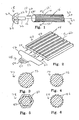
- a light radiating or diffusing structure including a body in the form of an optical fiber is generally designated as 10, and has a longitudinal axis 12 and a peripheral or circumferential surface 14 which extends parallel to the axis 12.
- the fiber 10 has a circular cross section centered on the axis 12.
- a plurality of longitudinal striations 16 are formed in the circumferential surface 14 parallel to the axis 12.
- a light source 18 includes, for example, a point light source in the form a halogen bulb 20 mounted in a housing 22.
- a reflector 24 directs the light from the bulb 20 into a light guide 26 which transmits the light into an input face or end 28 of the optical fiber 10 along the longitudinal axis 12 thereof.
- the light propagates through the fiber 10 along the axis 12 as indicated by an arrow 30. Due to internal reflections in the optical fiber 10 which are affected by the striations 16, the light is progressively radiated out of the circumferential surface 14 of the fiber 10 along the axis 12 in directions indicated by arrows 32, and also in directions 32' if the end of the fiber 10 opposite the end 28 is made reflective. In accordance with an important feature, the intensity of light radiated out the circumferential surface 14 is substantially uniform along the axis 12.
- FIG. 2 An embodiment of the invention is illustrated in FIG. 2, including a body in the form of a light radiating panel 40 having a rectangular cross section centered on an axis 42.
- a plurality of longitudinal striations in the form of rectangular grooves 44 are formed in a rectangular surface 46 of the panel 40 parallel to the axis 42.
- the grooves 44 provide the same function as the striations 16 in the surface 14 of the optical fiber 10 illustrated in FIG. 1, and may be formed by molding, cutting, etching, cleaving, or any other suitable method.
- a light source 48 includes a point light source in the form a halogen bulb 50 mounted in a housing 52.
- a reflector 54 directs the light from the bulb 50 into a light guide 56 which transmits the light into an input face or end 58 of the panel 40 along the longitudinal axis 42 thereof.
- the light guide 56 may include a plurality of optical fibers which are circularly bundled together at their ends facing the bulb 50, and spread out at their ends facing the panel 40 into a linear shape conjugate to the input end 58 of the panel 40.
- the light propagates through the panel 40 along the axis 42 as indicated by arrows 60. Due to internal reflections in the panel 40 which are affected by the channels 44, the light is progressively radiated out of the circumferential surface 46 of the panel 40 along the axis 42 in a direction which is generally perpendicular to the surface 46 as indicated by an arrow 62. As with the optical fiber 10, the intensity of light radiated out the rectangular surface 46 is substantially uniform along the axis 42.
- the surfaces of the panel 40 other than the light input end 58 and the light radiating surface 46 are made highly reflective to enable radiation of light only out through the surface 46. This may be accomplished by polishing these surfaces to a high degree, or forming a reflective coating of aluminum or the like on the surfaces by evaporation, sputtering, or any other suitable method.
- the striations may have a variety of cross sections as illustrated in FIGs. 3 to 6.
- an optical fiber 70 is formed with striations in the form of ridges 72 having a round, or circular cross section.
- an optical fiber 74 is formed with striations in the form of grooves 76 having a V-shaped cross section.
- an optical fiber 78 is formed with striations in the form of ridges 80 having a V-shaped cross section.
- the ridges 80 combine to form a hexagonal shape.
- the optical fiber 78 also includes a cladding layer 82 which conforms to the shape of the underlying ridges 80.
- FIG. 6 illustrates an optical fiber 84 formed with striations in the form of grooves 86 having a rectangular cross section.
- the optical fiber or panel may be formed of any light transmissible material, such as glass or acrylic resin.
- a cladding layer may be formed over the striations in any alternative form of the structure in the manner illustrated in FIG. 5.
- the cladding layer where provided, preferably has an index of refraction which is lower than that of the underlying structure. It is also within the scope of the invention to form the panel of a material having an index of refraction which is nonuniform throughout the cross section of the structure.
- the present longitudinal striations affect the internal reflection of light by creating additional reflections between the walls of adjacent striations. Each of these additional reflections causes the angle of incidence of the respective light rays to increase relative to the circumferential surface of the fiber. At a certain distance along the fiber, the angle of incidence of a given light ray will be increased by these multiple reflections beyond the angle of total internal reflection of the fiber, and be radiated out the circumferential surface of the fiber. The effect is essentially similar for the case of a panel structure formed with longitudinal striations. The exact mechanism by which the composite reflections interact with each other is complex and not fully understood.
- the amount of radiation increase or decrease along the length of the structure. This can be accomplished by varying the number, width, and/or depth of the striations. Increasing the width and/or depth of the striations increases the amount of radiated light.
- the present light radiating structure can be fabricated using a variety of conventional methods, such as molding or casting, which will not be described in detail.
- FIG. 9 Another method of forming an optical fiber with longitudinal striations is illustrated in FIG. 9.
- An optical fiber 95 illustrated in broken line is drawn or forced through a die 96 in the direction of an arrow 98.
- the die 96 has an inner surface 100 formed with a shape conjugate to the desired striations.
- the fiber 95 may be forced through the die 96 at room temperature, or heated to facilitate formation of the striations. Where the fiber 95 is heated, the temperature is selected to be slightly below the melting point of the material of the fiber 95. This temperature is appoximately 130°C for an acrylic fiber, and 900°C for a glass fiber.
- the fiber may be subsequentially subjected to heat and tension to stretch the fiber 95 and make the striations smaller.
- FIG. 10 An apparatus 102 for fabricating an optical fiber is illustrated in FIG. 10, and comprises a pipe heater 104.
- the heater 104 includes a hollow pipe provided with a suitable heating element (not shown) such that the interior of the pipe is maintained at a desired elevated temperature. Further illustrated are a thermocouple 106 and a control unit 108 for regulating the temperature inside the heater 104.
- An optical fiber 110 made of glass, acrylic resin, or the like is fed through the heater 104 from a supply spool 112 to a take-up spool 114.
- a suitable longitudinal tension is applied to the fiber 110 by means of inlet and outlet pulleys 116 and 118 respectively.
- the fiber 110 is cooled prior to entering the heater 104 by a cold air jet 120, and after emerging from the heater 104 by a cold air jet 122.
- the hot and cold temperatures, tension, and transit time through the heater 104 are selected to cause the desired longitudinal striations to be formed on the surface of the fiber 110.
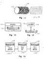
- FIG. 11 illustrates an optical fiber 124 which was subjected to thermal shock processing (cool/heat/cool) in an apparatus such as illustrated in FIG. 10, but with a small amount or no tension applied to the fiber 124.
- the process results in the formation of shapes in the circumferential surface of the fiber 124 which may be referred to as "microbends" 126.
- the microbends 126 are generally oriented along the longitudinal axis of the fiber 124, but are relatively short, and may extend in random directions also.
- a circumferential surface consisting of pure microbends 126 has properties similar to a surface which is roughened as in the prior art. However, if the microbends 126 are formed under conditions which make them sufficiently elongated along the axis of the fiber 124, they will produce an effect which is intermediate between pure microbends and longitudinal striations, and may be suitable for certain applications.
- Longitudinal striations in the circumferential surface of an optical fiber as desired may be formed using a combination of heating and tension. Heating of the fiber urges it to shrink longitudinally, and form microbends. However, if the ends of the fiber are clamped or restrained during heating to prevent shrinkage, the resulting tension results in the formation of the desired longitudinal striations. The formation is enhanced by cooling the fiber before and after heating to create a thermal shock. If desired, the tension applied to the ends of the fiber may be increased or decreased relative to the tension which is induced by shrinkage of the fiber.
- FIGs. 12 and 13 Alternative means of heating an optical fiber, panel, or other structure are illustrated in FIGs. 12 and 13.
- an optical fiber 128 is mounted in a fixture 130 which provides support, and also clamps the ends of the fiber 128 to prevent shrinkage.
- the fixture 130 is placed in an encolsure 132 in which the fiber 128 is exposed to energy from a source 134.
- the source 134 may produce energy in the form of microwaves, radiant (thermal) energy, or any other form which causes the optical fiber 128 to be heated to a temperature sufficient to form the longitudinal striations.
- FIG. 13 illustrates a source 136 for applying energy to the non-enclosed optical fiber 128.
- the source 136 may be a laser, infrared heater, parabolic mirror for focussing solar energy, etc.
- the source 136 may radiate energy onto the entire length of the fiber 128, or may radiate energy onto a small portion of the fiber 128 and be moved relative to the fiber 128 to sequentially apply energy along the entire length thereof.
- FIG. 14 Another method of fabricating a structure is illustrated in FIG. 14. Three tanks are provided, a first tank 140 filled with a cold fluid such as ice water, a second tank 142 filled with a hot fluid such as silicon or salad oil, and a third tank 144 filled with a cold fluid such as ice water.
- a first tank 140 filled with a cold fluid such as ice water
- a second tank 142 filled with a hot fluid such as silicon or salad oil
- a third tank 144 filled with a cold fluid such as ice water.
- the temperature in the tanks 140 and 144 is preferably on the order of 5°C, whereas the temperature of the oil in the tank 142 is approximately 142°C, or slightly above the melting point of the resin.
- the optical fiber 128 supported in the fixture 130 is successively immersed in the tanks 140, 142, and 144.
- the immersion time in the cold water tank 140 may be approximately 30 seconds.
- the immersion time in the hot oil tank 142 may be approximately 3 seconds, whereas the immersion time in the cold water tank 144 may be approximately 30 seconds.
- Light was introduced into one end of the resulting structure using a light source 18 including a 150 W halogen lamp 20 such as illustrated in FIG. 1.
- the light radiated out of the circumferential surface of the structure was visually observed to be substantially uniform over the length of the structure, except for approximately the first 15 cm from the light receiving end.
- Three stainless steel tanks which were 1000 mm long, 100 mm wide, and 50 mm high were provided.
- a 1000 mm long x 100 mm wide, 800 W sheet rubber heater was glued to the bottom of one of the tanks.
- the tank to which the heater was attached was enclosed in a wooden box. This tank was filled with salad oil, and heated to 142 ⁇ 1°C.
- the other two tanks were filled with ice water, and maintained at a temperature of 5°C or lower.
- the light source used in EXAMPLE 1 was used to introduce light into one end of the fiber.
- the amount of luminous flux entering the fiber was measured to be 8.8 Im.
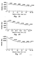
- the distribution of radiated light intensity along the center 60 mm in which the striations were formed is illustrated in FIG. 15.
- the amount of luminous flux radiated from the entire circumferential surface of the fiber was measured to be 5.3 Im. This amount was confirmed by converting the measured light intensity in FIG. 15 into luminous flux.
- the amount of luminous flux radiated from the opposite end of the fiber was measured to be 3.5 Im.
- approximately 60% of the luminous flux which entered the fiber was consumed along the striated portion, and approximately 100% of the consumed light was radiated out the surface of the fiber in the striated portion.
- An acrylic resin panel which was 600 mm long, 25 mm wide, and 3 mm thick had light reflective aluminum film coated on all surfaces thereof except the light receiving edge, and the light radiating surface thereof. Forty-one grooves having a rectangular cross section as illustrated in FIG. 2 were cut using a blade into the light radiating surface of the panel, parallel to the 600 mm length thereof. The grooves were 0.4 mm wide and 0.4 mm deep, with 2.5 mm spacing provided between adjacent grooves.
- the light source 58 illustrated in FIG. 2 was used to introduce approximately 167 Im of luminous flux into the light receiving edge of the panel as shown in the drawing.
- the intensity of radiated light along the length of the panel is illustrated in FIG. 17.
- the data implies that approximately 145.5 Im of luminous flux, or 87% of the input light flux, was radiated out the surface of the panel formed with the striations.
Landscapes
- Physics & Mathematics (AREA)
- General Physics & Mathematics (AREA)
- Optics & Photonics (AREA)
- Light Guides In General And Applications Therefor (AREA)
- Farming Of Fish And Shellfish (AREA)
- Mechanical Coupling Of Light Guides (AREA)
Claims (2)
- Lichtausstrahlende Vorrichtung, aufweisend:ein optisches Paneel (40), das einen rechteckigen Querschnitt aufweist, der auf eine Längsachse (42) des Paneels (40) zentriert ist, und das zwei Paneel-Flächen, welche sich parallel zueinander und parallel zu der Längsachse (42) erstrecken, zwei Seitenflächen, die einander gegenüberliegen, und zwei Endflächen aufweist, die einander gegenüberliegen;eine Lichtquelle (50) undeinen Lichtleiter (56) zum Leiten von Licht von der Lichtquelle (50) in eine der Endflächen des optischen Paneels (40) entlang der Längsachse (42) davon, wobeieine Mehrzahl von Längsrillen (44) oder Längsrippen in einer (46) der Paneel-Flächen einstückig ausgebildet sind und sich parallel zu und entlang der Längsachse (42) erstrecken, wobei die Längsrillen (44) oder Längsrippen Wände aufweisen, die jeweilige Abschnitte der einen (46) der Paneel-Flächen derart bilden, dass das in die eine (46) der End-Flächen des optischen Paneels (40) eintretende Licht innen zwischen den Wänden reflektiert wird, und die Mehrfachreflexionen bewirken, dass der Einfallswinkel entlang der Längsachse (42) über den Winkel der inneren Totalreflexion des Paneels hinaus vergrößert wird, wodurch die eine der Paneel-Flächen als lichtausstrahlende Fläche bereitgestellt ist, die das Licht in im Wesentlichen gleichbleibender Weise entlang der Längsachse (42) ausstrahlt.
- Struktur nach Anspruch 1, wobei die Seitenflächen, die Paneel-Fläche, die der lichtausstrahlenden Fläche gegenüberliegt, und die Endfläche, die der Endfläche gegenüberliegt, in die das Licht geleitet wird, mit Reflexionsmitteln ausgestattet sind.
Priority Applications (3)
| Application Number | Priority Date | Filing Date | Title |
|---|---|---|---|
| EP98115295A EP0903593B1 (de) | 1990-04-10 | 1990-04-10 | Gestreifter Lichtstreukörper und Herstellungsmethode dafür |
| DE1990634233 DE69034233T2 (de) | 1990-04-10 | 1990-04-10 | Rippen-Lichtdiffusor und Herstellungsverfahren für diesen |
| AT98115295T ATE346318T1 (de) | 1990-04-10 | 1990-04-10 | Gestreifter lichtstreukörper und herstellungsmethode dafür |
Applications Claiming Priority (2)
| Application Number | Priority Date | Filing Date | Title |
|---|---|---|---|
| EP98115295A EP0903593B1 (de) | 1990-04-10 | 1990-04-10 | Gestreifter Lichtstreukörper und Herstellungsmethode dafür |
| EP90303857A EP0451382B1 (de) | 1990-04-10 | 1990-04-10 | Gestreifter Lichtstreukörper und dessen Herstellungsmethode |
Related Parent Applications (1)
| Application Number | Title | Priority Date | Filing Date |
|---|---|---|---|
| EP90303857A Division EP0451382B1 (de) | 1990-04-10 | 1990-04-10 | Gestreifter Lichtstreukörper und dessen Herstellungsmethode |
Publications (2)
| Publication Number | Publication Date |
|---|---|
| EP0903593A1 EP0903593A1 (de) | 1999-03-24 |
| EP0903593B1 true EP0903593B1 (de) | 2006-11-22 |
Family
ID=8205366
Family Applications (1)
| Application Number | Title | Priority Date | Filing Date |
|---|---|---|---|
| EP98115295A Expired - Lifetime EP0903593B1 (de) | 1990-04-10 | 1990-04-10 | Gestreifter Lichtstreukörper und Herstellungsmethode dafür |
Country Status (4)
| Country | Link |
|---|---|
| EP (1) | EP0903593B1 (de) |
| AT (1) | ATE177211T1 (de) |
| DE (1) | DE69032973T2 (de) |
| ES (1) | ES2277372T3 (de) |
Families Citing this family (1)
| Publication number | Priority date | Publication date | Assignee | Title |
|---|---|---|---|---|
| JP3085671B1 (ja) | 1999-05-12 | 2000-09-11 | 株式会社ナカニシ | 歯科用ハンドピース及び光路ユニットの成形方法 |
Family Cites Families (9)
| Publication number | Priority date | Publication date | Assignee | Title |
|---|---|---|---|---|
| DE1203310B (de) * | 1961-06-24 | 1965-10-21 | Saba Gmbh | Verfahren zum Profilieren einer der Herstellung von optischen Blenden mit Rillenprofil dienenden Walze |
| US3829675A (en) * | 1973-04-30 | 1974-08-13 | R Mariani | Lighting means for underwater illumination |
| DE2827573C2 (de) * | 1978-06-23 | 1983-02-03 | Blaupunkt-Werke Gmbh, 3200 Hildesheim | Großflächige Lichtquelle |
| JPS5947428A (ja) * | 1982-09-13 | 1984-03-17 | Asahi Chem Ind Co Ltd | 亀裂を有する繊維の製造方法 |
| JPS59111604A (ja) * | 1982-12-17 | 1984-06-27 | Sumitomo Electric Ind Ltd | 太陽光散乱装置 |
| US4615579A (en) * | 1983-08-29 | 1986-10-07 | Canadian Patents & Development Ltd. | Prism light guide luminaire |
| EP0152493B1 (de) * | 1984-02-02 | 1988-07-27 | Kei Mori | Leuchte |
| JPS61122609A (ja) * | 1984-11-19 | 1986-06-10 | Iseki & Co Ltd | 太陽光伝送装置における光フアイバ− |
| JPH0614162Y2 (ja) * | 1987-06-19 | 1994-04-13 | 三菱レイヨン株式会社 | 光フアイバ粗面加工装置 |
-
1990
- 1990-04-10 EP EP98115295A patent/EP0903593B1/de not_active Expired - Lifetime
- 1990-04-10 ES ES98115295T patent/ES2277372T3/es not_active Expired - Lifetime
- 1990-04-10 DE DE69032973T patent/DE69032973T2/de not_active Expired - Fee Related
- 1990-04-10 AT AT90303857T patent/ATE177211T1/de not_active IP Right Cessation
Also Published As
| Publication number | Publication date |
|---|---|
| DE69032973D1 (de) | 1999-04-08 |
| ES2277372T3 (es) | 2007-07-01 |
| ATE177211T1 (de) | 1999-03-15 |
| EP0903593A1 (de) | 1999-03-24 |
| DE69032973T2 (de) | 1999-12-02 |
Similar Documents
| Publication | Publication Date | Title |
|---|---|---|
| US5233679A (en) | Striated light diffuser and method of forming the same | |
| US5222795A (en) | Controlled light extraction from light guides and fibers | |
| US5021928A (en) | Flat panel illumination system | |
| US5183323A (en) | Flat panel illumination system | |
| US5857761A (en) | Illumination device | |
| EP0495273B1 (de) | Dünne Plattenleuchte | |
| US5631994A (en) | Structured surface light extraction overlay and illumination system | |
| US5495541A (en) | Optical delivery device with high numerical aperture curved waveguide | |
| US5136480A (en) | Thin panel illuminator | |
| AU715687B2 (en) | Side lighting optical conduit | |
| AU619591B2 (en) | Light emitting panel assemblies and method of making same | |
| CA2004087C (en) | Hollow lightpipe and method for its manufacture | |
| US4933815A (en) | Light pipe for decorative illumination | |
| NZ205144A (en) | Light guide with diffusing strip | |
| JPH06201917A (ja) | 光ファイバ | |
| US6137928A (en) | Optical fiber light distribution system and method of manufacture and illumination | |
| KR940009705A (ko) | 중앙 광원으로부터 단열된 분산 광 네트워크 | |
| CN1315297A (zh) | 激光光固化系统 | |
| US8031998B2 (en) | Illumination fiber optic ribbon | |
| US5060119A (en) | Light pipe for decorative illumination | |
| US5372756A (en) | Method of forming striated light diffuser | |
| EP0903593B1 (de) | Gestreifter Lichtstreukörper und Herstellungsmethode dafür | |
| CA2014309C (en) | Striated light diffuser and method of forming the same | |
| Sato et al. | High power, high intensity CO infrared laser transmission through As2S3 glass fibers | |
| KR20090119561A (ko) | 광파이프 및 이를 구비한 조명 장치 |
Legal Events
| Date | Code | Title | Description |
|---|---|---|---|
| PUAI | Public reference made under article 153(3) epc to a published international application that has entered the european phase |
Free format text: ORIGINAL CODE: 0009012 |
|
| AC | Divisional application: reference to earlier application |
Ref document number: 451382 Country of ref document: EP |
|
| AK | Designated contracting states |
Kind code of ref document: A1 Designated state(s): AT BE CH DE DK ES FR GB GR IT LI LU NL SE |
|
| 17P | Request for examination filed |
Effective date: 19990923 |
|
| 17Q | First examination report despatched |
Effective date: 20010611 |
|
| APAF | Appeal reference modified |
Free format text: ORIGINAL CODE: EPIDOSCREFNE |
|
| APBT | Appeal procedure closed |
Free format text: ORIGINAL CODE: EPIDOSNNOA9E |
|
| GRAP | Despatch of communication of intention to grant a patent |
Free format text: ORIGINAL CODE: EPIDOSNIGR1 |
|
| RIC1 | Information provided on ipc code assigned before grant |
Ipc: F21S 2/00 20060101ALI20060622BHEP Ipc: F21V 8/00 20060101ALI20060622BHEP Ipc: G02B 6/04 20060101ALI20060622BHEP Ipc: G02B 5/02 20060101AFI20060622BHEP |
|
| GRAS | Grant fee paid |
Free format text: ORIGINAL CODE: EPIDOSNIGR3 |
|
| GRAA | (expected) grant |
Free format text: ORIGINAL CODE: 0009210 |
|
| AC | Divisional application: reference to earlier application |
Ref document number: 0451382 Country of ref document: EP Kind code of ref document: P |
|
| AK | Designated contracting states |
Kind code of ref document: B1 Designated state(s): AT BE CH DE DK ES FR GB GR IT LI LU NL SE |
|
| PG25 | Lapsed in a contracting state [announced via postgrant information from national office to epo] |
Ref country code: LI Free format text: LAPSE BECAUSE OF FAILURE TO SUBMIT A TRANSLATION OF THE DESCRIPTION OR TO PAY THE FEE WITHIN THE PRESCRIBED TIME-LIMIT Effective date: 20061122 Ref country code: CH Free format text: LAPSE BECAUSE OF FAILURE TO SUBMIT A TRANSLATION OF THE DESCRIPTION OR TO PAY THE FEE WITHIN THE PRESCRIBED TIME-LIMIT Effective date: 20061122 Ref country code: BE Free format text: LAPSE BECAUSE OF FAILURE TO SUBMIT A TRANSLATION OF THE DESCRIPTION OR TO PAY THE FEE WITHIN THE PRESCRIBED TIME-LIMIT Effective date: 20061122 Ref country code: AT Free format text: LAPSE BECAUSE OF FAILURE TO SUBMIT A TRANSLATION OF THE DESCRIPTION OR TO PAY THE FEE WITHIN THE PRESCRIBED TIME-LIMIT Effective date: 20061122 |
|
| RAP1 | Party data changed (applicant data changed or rights of an application transferred) |
Owner name: OYAMA, NOBUO |
|
| REG | Reference to a national code |
Ref country code: GB Ref legal event code: FG4D |
|
| RIN1 | Information on inventor provided before grant (corrected) |
Inventor name: OYAMA, NOBUO |
|
| REG | Reference to a national code |
Ref country code: CH Ref legal event code: EP |
|
| REF | Corresponds to: |
Ref document number: 69034233 Country of ref document: DE Date of ref document: 20070104 Kind code of ref document: P |
|
| PG25 | Lapsed in a contracting state [announced via postgrant information from national office to epo] |
Ref country code: SE Free format text: LAPSE BECAUSE OF FAILURE TO SUBMIT A TRANSLATION OF THE DESCRIPTION OR TO PAY THE FEE WITHIN THE PRESCRIBED TIME-LIMIT Effective date: 20070222 Ref country code: DK Free format text: LAPSE BECAUSE OF FAILURE TO SUBMIT A TRANSLATION OF THE DESCRIPTION OR TO PAY THE FEE WITHIN THE PRESCRIBED TIME-LIMIT Effective date: 20070222 |
|
| NLR4 | Nl: receipt of corrected translation in the netherlands language at the initiative of the proprietor of the patent | ||
| REG | Reference to a national code |
Ref country code: CH Ref legal event code: PL |
|
| ET | Fr: translation filed | ||
| REG | Reference to a national code |
Ref country code: ES Ref legal event code: FG2A Ref document number: 2277372 Country of ref document: ES Kind code of ref document: T3 |
|
| PLBE | No opposition filed within time limit |
Free format text: ORIGINAL CODE: 0009261 |
|
| STAA | Information on the status of an ep patent application or granted ep patent |
Free format text: STATUS: NO OPPOSITION FILED WITHIN TIME LIMIT |
|
| 26N | No opposition filed |
Effective date: 20070823 |
|
| PG25 | Lapsed in a contracting state [announced via postgrant information from national office to epo] |
Ref country code: GR Free format text: LAPSE BECAUSE OF FAILURE TO SUBMIT A TRANSLATION OF THE DESCRIPTION OR TO PAY THE FEE WITHIN THE PRESCRIBED TIME-LIMIT Effective date: 20070223 |
|
| PGFP | Annual fee paid to national office [announced via postgrant information from national office to epo] |
Ref country code: ES Payment date: 20080424 Year of fee payment: 19 |
|
| PGFP | Annual fee paid to national office [announced via postgrant information from national office to epo] |
Ref country code: IT Payment date: 20080426 Year of fee payment: 19 |
|
| PGFP | Annual fee paid to national office [announced via postgrant information from national office to epo] |
Ref country code: NL Payment date: 20080422 Year of fee payment: 19 |
|
| PGFP | Annual fee paid to national office [announced via postgrant information from national office to epo] |
Ref country code: FR Payment date: 20080418 Year of fee payment: 19 |
|
| PGFP | Annual fee paid to national office [announced via postgrant information from national office to epo] |
Ref country code: GB Payment date: 20080423 Year of fee payment: 19 |
|
| PGFP | Annual fee paid to national office [announced via postgrant information from national office to epo] |
Ref country code: DE Payment date: 20081031 Year of fee payment: 19 |
|
| PG25 | Lapsed in a contracting state [announced via postgrant information from national office to epo] |
Ref country code: LU Free format text: LAPSE BECAUSE OF NON-PAYMENT OF DUE FEES Effective date: 20070410 |
|
| GBPC | Gb: european patent ceased through non-payment of renewal fee |
Effective date: 20090410 |
|
| NLV4 | Nl: lapsed or anulled due to non-payment of the annual fee |
Effective date: 20091101 |
|
| REG | Reference to a national code |
Ref country code: FR Ref legal event code: ST Effective date: 20091231 |
|
| PG25 | Lapsed in a contracting state [announced via postgrant information from national office to epo] |
Ref country code: DE Free format text: LAPSE BECAUSE OF NON-PAYMENT OF DUE FEES Effective date: 20091103 |
|
| PG25 | Lapsed in a contracting state [announced via postgrant information from national office to epo] |
Ref country code: NL Free format text: LAPSE BECAUSE OF NON-PAYMENT OF DUE FEES Effective date: 20091101 |
|
| PG25 | Lapsed in a contracting state [announced via postgrant information from national office to epo] |
Ref country code: GB Free format text: LAPSE BECAUSE OF NON-PAYMENT OF DUE FEES Effective date: 20090410 Ref country code: FR Free format text: LAPSE BECAUSE OF NON-PAYMENT OF DUE FEES Effective date: 20091222 |
|
| REG | Reference to a national code |
Ref country code: ES Ref legal event code: FD2A Effective date: 20090411 |
|
| PG25 | Lapsed in a contracting state [announced via postgrant information from national office to epo] |
Ref country code: ES Free format text: LAPSE BECAUSE OF NON-PAYMENT OF DUE FEES Effective date: 20090411 |
|
| PG25 | Lapsed in a contracting state [announced via postgrant information from national office to epo] |
Ref country code: IT Free format text: LAPSE BECAUSE OF NON-PAYMENT OF DUE FEES Effective date: 20090410 |