EP0903474A1 - Anordnung zum Einkapseln einer Nebenwelle einer Hubkolben-Brennkraftmaschine - Google Patents
Anordnung zum Einkapseln einer Nebenwelle einer Hubkolben-Brennkraftmaschine Download PDFInfo
- Publication number
- EP0903474A1 EP0903474A1 EP98117181A EP98117181A EP0903474A1 EP 0903474 A1 EP0903474 A1 EP 0903474A1 EP 98117181 A EP98117181 A EP 98117181A EP 98117181 A EP98117181 A EP 98117181A EP 0903474 A1 EP0903474 A1 EP 0903474A1
- Authority
- EP
- European Patent Office
- Prior art keywords
- oil
- arrangement according
- capsule device
- crankcase
- web
- Prior art date
- Legal status (The legal status is an assumption and is not a legal conclusion. Google has not performed a legal analysis and makes no representation as to the accuracy of the status listed.)
- Granted
Links
- 238000002485 combustion reaction Methods 0.000 title claims description 17
- 239000002775 capsule Substances 0.000 claims description 46
- 238000002347 injection Methods 0.000 claims description 2
- 239000007924 injection Substances 0.000 claims description 2
- 238000005538 encapsulation Methods 0.000 abstract description 2
- 239000003921 oil Substances 0.000 description 60
- 239000010687 lubricating oil Substances 0.000 description 10
- 238000004519 manufacturing process Methods 0.000 description 3
- 238000013016 damping Methods 0.000 description 2
- 230000001419 dependent effect Effects 0.000 description 2
- 238000009434 installation Methods 0.000 description 2
- 238000012423 maintenance Methods 0.000 description 2
- 239000000463 material Substances 0.000 description 2
- 238000007789 sealing Methods 0.000 description 2
- 238000003466 welding Methods 0.000 description 2
- OPFJDXRVMFKJJO-ZHHKINOHSA-N N-{[3-(2-benzamido-4-methyl-1,3-thiazol-5-yl)-pyrazol-5-yl]carbonyl}-G-dR-G-dD-dD-dD-NH2 Chemical compound S1C(C=2NN=C(C=2)C(=O)NCC(=O)N[C@H](CCCN=C(N)N)C(=O)NCC(=O)N[C@H](CC(O)=O)C(=O)N[C@H](CC(O)=O)C(=O)N[C@H](CC(O)=O)C(N)=O)=C(C)N=C1NC(=O)C1=CC=CC=C1 OPFJDXRVMFKJJO-ZHHKINOHSA-N 0.000 description 1
- 229940126086 compound 21 Drugs 0.000 description 1
- 238000010276 construction Methods 0.000 description 1
- 238000005187 foaming Methods 0.000 description 1
- 238000005461 lubrication Methods 0.000 description 1
- 239000000155 melt Substances 0.000 description 1
- 239000002245 particle Substances 0.000 description 1
- 230000000149 penetrating effect Effects 0.000 description 1
- 230000002093 peripheral effect Effects 0.000 description 1
- 230000002787 reinforcement Effects 0.000 description 1
Images


Classifications
-
- F—MECHANICAL ENGINEERING; LIGHTING; HEATING; WEAPONS; BLASTING
- F01—MACHINES OR ENGINES IN GENERAL; ENGINE PLANTS IN GENERAL; STEAM ENGINES
- F01M—LUBRICATING OF MACHINES OR ENGINES IN GENERAL; LUBRICATING INTERNAL COMBUSTION ENGINES; CRANKCASE VENTILATING
- F01M11/00—Component parts, details or accessories, not provided for in, or of interest apart from, groups F01M1/00 - F01M9/00
- F01M11/0004—Oilsumps
-
- F—MECHANICAL ENGINEERING; LIGHTING; HEATING; WEAPONS; BLASTING
- F02—COMBUSTION ENGINES; HOT-GAS OR COMBUSTION-PRODUCT ENGINE PLANTS
- F02B—INTERNAL-COMBUSTION PISTON ENGINES; COMBUSTION ENGINES IN GENERAL
- F02B77/00—Component parts, details or accessories, not otherwise provided for
- F02B77/11—Thermal or acoustic insulation
- F02B77/13—Acoustic insulation
-
- F—MECHANICAL ENGINEERING; LIGHTING; HEATING; WEAPONS; BLASTING
- F01—MACHINES OR ENGINES IN GENERAL; ENGINE PLANTS IN GENERAL; STEAM ENGINES
- F01M—LUBRICATING OF MACHINES OR ENGINES IN GENERAL; LUBRICATING INTERNAL COMBUSTION ENGINES; CRANKCASE VENTILATING
- F01M1/00—Pressure lubrication
- F01M1/02—Pressure lubrication using lubricating pumps
- F01M2001/0253—Pressure lubrication using lubricating pumps characterised by the pump driving means
- F01M2001/0276—Pressure lubrication using lubricating pumps characterised by the pump driving means driven by a balancer shaft
-
- F—MECHANICAL ENGINEERING; LIGHTING; HEATING; WEAPONS; BLASTING
- F01—MACHINES OR ENGINES IN GENERAL; ENGINE PLANTS IN GENERAL; STEAM ENGINES
- F01M—LUBRICATING OF MACHINES OR ENGINES IN GENERAL; LUBRICATING INTERNAL COMBUSTION ENGINES; CRANKCASE VENTILATING
- F01M11/00—Component parts, details or accessories, not provided for in, or of interest apart from, groups F01M1/00 - F01M9/00
- F01M11/0004—Oilsumps
- F01M2011/0029—Oilsumps with oil filters
Definitions
- the invention relates to an arrangement for encapsulating a secondary shaft of a reciprocating piston internal combustion engine with a crankcase and one arranged on the crankcase Oil pan according to the preamble of claim 1 and an internal combustion engine according to the Preamble of claim 16.
- the present invention is therefore based on the object of an improved arrangement and to provide an internal combustion engine of the above type, the above mentioned disadvantages are overcome.
- a trough-shaped capsule device with an open side, a tub floor and one that runs around the open side Trough edge is provided, which with the open side towards the crankcase and enclosing the auxiliary shaft and encapsulating it against the oil pan, arranged in the oil pan is.
- Fixing means are expediently on the capsule device on the crankcase side formed, for example, as mounting holes or as at least one clip closure and are particularly preferably formed around the tub rim.
- the capsule device has in the tub floor an oil intake opening, which is arranged such that when the capsule device is mounted An intake port of an oil pump with this oil intake opening on the crankcase side connected is.
- the oil suction opening is advantageously provided with a sieve.
- the diagonal arrangement of the sieve provides a particularly large filter area.
- an uninterrupted oil supply to the oil pump is achieved in that the oil intake opening oil pan side has a snorkel, which in an oil sump in the Oil pan protrudes and preferably a snorkel connection on the oil pan side at the oil intake opening is arranged.
- a contour of the Trough edge of the capsule device essentially follows this web, so that the Capsule device can be flanged to this web, can advantageously a large part of the lubricating oil circulating in the crankcase is directed past the capsule device and only a smaller, predetermined part of the lubricating oil penetrates the crankcase side to lubricate the auxiliary shaft in the capsule device.
- the support structure on the oil pan side one of an outer edge of the support structure spaced, circumferential web, with a contour of the tub edge Capsule device essentially follows this web, so that the capsule device is on this web can be flanged, can advantageously a large part of the in the crankcase circulating lubricating oil are directed past the capsule device and only one smaller, predetermined part of the lubricating oil penetrates into the secondary shaft to lubricate it Capsule device.
- the capsule device in the trough bottom at least one oil drain opening advantageously has a defined oil-conducting connection between the oil pan and an interior of the capsule device created, whereby the interior the capsule device is connected to an oil circulation in the crankcase
- the capsule device is advantageous integrally formed as an injection molded part.
- the reciprocating piston internal combustion engine has a crankcase, not shown, with one therein rotating crankshaft 1. Lateral walls of the crankcase are over the crankshaft center 2 in the direction of an oil pan, not shown, into one Flange level E guided. At this flange level E includes in the direction of the oil pan connected to the walls of the crankcase, labeled 3 in total Component, which is referred to below as support structure 3. This is essentially plate-shaped and extends in the longitudinal direction L and transverse direction Q of Crankcase and separates through its connection to the opening area of the crankcase surrounding flange opposite the crank drive designated overall with 4 the oil pan essentially.
- the surface of the support structure 3 facing the crank mechanism 4 is at least in the region of Crank cheeks 6 of the crank mechanism 4 in accordance with the rotation there Conrod violin structure formed.
- the Support structure 3 On its surface 7 facing away from the crank mechanism 4 and facing the oil pan, the Support structure 3 formed in one piece and of the same material, each an undivided bearing 8 and 9 bearing blocks 10 and 11.
- the support structure 3 is essentially rectangular, with 12 on the long sides and 13 mounting eyes 14 are arranged for performing screw connections.
- the long side 12 is essentially covered in the illustration in FIG. 1. With the Screw connections, the support structure 3 is fixed in the flange plane E on the crankcase.
- auxiliary shaft In the assembled state of the support structure 3 according to Figures 2, 3 and 4 is in the bearings 8 and 9 rotatably held a total of 20 designated auxiliary shaft.
- This is integral and provided in one piece with a leveling compound 21 and initially from the end face 16 inserted through the bearing 9 and then through the bearing 8.
- stepped pin 22 of the auxiliary shaft 20th On one plugged in Condition of the bearing 8 penetrating, stepped pin 22 of the auxiliary shaft 20th is a drive wheel 23 designed as a chain wheel and then a further balancing mass 24 put on.
- This arrangement ensures together with one at the On the inside of the end wall 17 adjoining collar 26 of the secondary shaft 20 has an axial bearing, while the bearing 9 is designed as a floating bearing.
- the floating mounting of the balancing mass 21 ensures that the space is optimally approached this balancing mass 21 to the support structure 3.
- This has a section 7a appropriately shaped contour surfaces 27 to create a free passage.
- Crossing stiffening ribs 30 are between the two bearing blocks 10 and 11 arranged, which intersect at intersection points 31.
- the support structure 3 has a channel system for lubricating oil. From the flange level E starting in the area of the bearing block 11 extends essentially transverse inflow channel 45, which extends to the bearing 9 there. In one shaft 46 protruding from surface 7 extends parallel to the auxiliary shaft 20 a supply channel 47 which intersects the inflow channel 45 and which feeds in the Lubricating oil to the bearing 8 promotes. The shaft 46 receiving the supply channel 47 runs along a series of crossing points 31.
- the surface 7 continues to bear a web 32 which is a capsule device according to the invention described below Drive shaft 20 adjacent.
- This web 32 extends from the end wall 17 spaced and parallel to the long side 13 along the end face 16 and again after internally offset essentially parallel to the other long side 12.
- In the area of this Longitudinal sides 12 and 13 are between these 32 web-like openings 33 for the web the passage of lubricating oil of the crank mechanism 4 arranged in the oil pan.
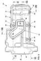
- FIG. 5 to 9 show the aforementioned capsule device 49 according to the invention in one preferred embodiment.
- This comprises a trough-like housing 50, which in a circumferential contour and in a peripheral tub rim which is only partially visible in FIG. 5 64 the contour of the web 32 of FIG. 4 is adapted such that it is on the web 32 can be flanged and the auxiliary shaft 20 encapsulates against an oil pan.
- the capsule device 49 further includes, in the preferred embodiment shown, mounting eyes 52, Clip connector 54, a snorkel flange with cover 56, a snorkel 58 and one Oil intake opening 60.
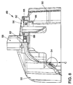
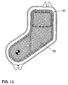
- FIG. 6 shows in detail the area of the oil suction opening 60 which, in addition to the snorkel flange with cover 56, also comprises a sieve 62.
- the cover 56 with the snorkel 58 (not visible in FIG. 6) is arranged on the oil pan side, ie in the installed position below the capsule device 49.
- a connecting piece 66 formed integrally with the housing 50 is provided on an opposite side facing the crankcase or the support structure 3 in an interior of the capsule device 49.
- this connecting piece 66 interacts with an intake port 67 of the oil pump in such a way that the oil pump is connected to the snorkel 58 and pumps and delivers oil from an oil sump.
- FIG. 7 the snorkel 58 is shown in solid lines for a specific internal combustion engine, while a shortened snorkel 58 for a specific internal combustion engine is shown in dashed lines with a different stroke volume and / or a different installation position.
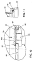
- FIG. 10 shows a detailed illustration of a fastening eye 52 on the housing 50
- Fastening the capsule device 49 is a screw on the oil pan side in the direction of arrow 70 53 performed by the mounting eye 52 and either on the crankcase side Crankcase or screwed to the attachment points 44 ( Figure 1) of the support structure 3.
- An annular web 59 integrally formed with the housing 50 in a depression 61 is plastically pressed by contacting the screw head 53 a and makes one separate sealing ring unnecessary.
- the screw torque is based on the crankcase or on the lead frame, but not on the housing 50. This means that no independent occurs Dissolve by creeping the housing material.
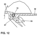
- the clip connectors 54 shown in detail in FIGS. 11 and 12 can be used in addition to the Fastening eyes 52 or be provided instead.
- the clip connector 54 includes a hook-shaped element 55, which is attached to the housing 50 via an elastic arm 57 is. When pushed onto the web 32, the hook-shaped element 55 engages around the Web 32, as shown in Figure 12, and thus secures the housing 50 in a predetermined Position below the crankcase. An inserted sealing cord 72 seals the housing 50 on a circumferential bearing surface on the web 32 against the interior of the surrounding oil pan.
- the clip connections 54 have the advantage that they are the same can be removed again simply and quickly, as previously by "clipping" the housing 50 were manufactured.
- the capsule device 49 can also be closed again quickly and easily disassemble, for example for later maintenance or repair work.
- the capsule device 49 advantageously prevents the rotating ones from “splashing" Counter shaft 20 in the oil sump, which leads to an undesirable foaming of the oil and unnecessary loss of work.
- the suction snorkel integrated in the capsule device 49 58 for the oil pump reduces the total number of parts when assembling the Internal combustion engine.
- the capsule device 49 for example, only takes on the auxiliary shaft 20 oil extracted for their lubrication and the oil flowing out of the crank mechanism becomes of such an embodiment completely past the auxiliary shaft 20 into the oil pan headed.
Landscapes
- Engineering & Computer Science (AREA)
- Physics & Mathematics (AREA)
- Acoustics & Sound (AREA)
- Mechanical Engineering (AREA)
- General Engineering & Computer Science (AREA)
- Chemical & Material Sciences (AREA)
- Combustion & Propulsion (AREA)
- Lubrication Details And Ventilation Of Internal Combustion Engines (AREA)
Abstract
Description
Durch diagonale Anordnung des Siebs steht eine besonders große Filterfläche zur Verfügung.
- Fig. 1
- eine perspektivische Ansicht von schräg unten auf eine Stützstruktur für ein Kurbelgehäuse zum Anbau einer Nebenwelle,
- Fig. 2
- eine perspektivische Ansicht einer in einer Hubkolben-Brennkraftmaschine verbauten Stützstruktur mit einem teilweise dargestellten Kurbeltrieb ohne Kurbelgehäuse,
- Fig. 3
- eine stirnseitige Seitenansicht zu Fig. 2,
- Fig. 4
- eine Seitenansicht zu Fig. 3,
- Fig. 5
- eine erfindungsgemäße Kapselvorrichtung in einer Ansicht von unten,
- Fig. 6
- einen Teil einer Schnittansicht entlang der Linie VI - VI von Fig. 5,
- Fig. 7
- einen Schnitt entlang der Linie VII - VII von Fig. 5,
- Fig. 8
- einen Schnitt entlang der Linie VIII - VIII von Fig. 5,
- Fig. 9
- eine Seitenansicht in Richtung S von Fig. 5,
- Fig. 10
- eine Detailansicht des Ausschnittes F von Fig. 7,
- Fig. 11
- eine Detailansicht des Ausschnittes E von Fig. 7,
- Fig. 12
- eine Detailansicht des Ausschnittes C von Fig. 8 und
- Fig. 13
- eine Aufsicht eines Schnorchelflansches mit Sieb.
In Figur 7 ist der Schnorchel 58 in ausgezogenen Linien für eine bestimmte Brennkraftmaschine gezeigt, während ein verkürzter Schnorchel 58 für eine bestimmte Brenkraftmaschine mit einem anderen Hubvolumen und/oder einer anderen Einbaulage gestrichelt dargestellt ist.
Claims (17)
- Anordnung zum Einkapseln einer Nebenwelle einer Hubkolben-Brennkraftmaschine mit einem Kurbelgehäuse und einer am Kurbelgehäuse angeordneten Ölwanne, dadurch gekennzeichnet, daß
eine wannenförmige Kapselvorrichtung (49) mit einer offenen Seite, einem Gehäuse (50) und einen um die offene Seite umlaufenden Wannenrand (64) vorgesehen ist, welche mit der offenen Seite in Richtung Kurbelgehäuse und die Nebenwelle umschließend und gegen die Ölwanne abkapselnd, in der Ölwanne angeordnet ist. - Anordnung nach Anspruch 1,
dadurch gekennzeichnet, daß
an der Kapselvorrichtung (49) kurbelgehäuseseitig Befestigungsmittel (52, 54) ausgebildet sind. - Anordnung nach Anspruch 2,
dadurch gekennzeichnet, daß
die Befestigungsmittel Befestigungsaugen (52) sind, durch welche Schrauben (53) hindurchsteckbar und kurbelgehäuseseitig festschraubbar sind. - Anordnung nach Anspruch 2,
dadurch gekennzeichnet, daß
die Befestigungsmittel wenigstens einen Clipverschluß (54) umfassen. - Anordnung nach einem der Ansprüche 2 bis 4,
dadurch gekennzeichnet, daß
die Befestigungsmittel (52, 54) an dem Wannenrand (64) ausgebildet sind. - Anordnung nach einem der vorhergehenden Ansprüche,
dadurch gekennzeichnet, daß
die Kapselvorrichtung (49) am Gehäuse (50) eine Ölansaugöffnung (60) aufweist, welche derart angeordnet ist, daß bei montierter Kapselvorrichtung (49) kurbelgehäuseseitig ein Ansaugstutzen einer Ölpumpe mit dieser Ölansaugöffnung (60) verbunden ist. - Anordnung nach Anspruch 6,
dadurch gekennzeichnet, daß
die Ölansaugöffnung (60) mit einem Sieb (62) versehen ist. - Anordnung nach Anspruch 6 oder 7,
dadurch gekennzeichnet, daß
die Ölansaugöffnung (60) ölwannenseitig einen Schnorchel (58) aufweist, welcher in einen Ölsumpf in der Ölwanne ragt. - Anordnung nach Anspruch 6, dadurch gekennzeichnet, daß in Einbaulage das Sieb (62) bezüglich des Ölströmweges schräg angeordnet ist.
- Anordnung nach einem der Ansprüche 6 bis 9,
dadurch gekennzeichnet, daß
ölwannenseitig an der Ölansaugöffnung (60) ein Schnorchelstutzen mit Deckel (56) angeordnet ist. - Anordnung nach einem der vorhergehenden Ansprüche,
dadurch gekennzeichnet, daß
das Kurbelgehäuse ölwannenseitig einen von einem äußeren Rand des Kurbelgehäuses beabstandeten, umlaufenden Steg (32) aufweist, wobei eine Kontur des Wannenrandes (64) der Kapselvorrichtung (49) im wesentlichen diesem Steg (32) folgt, so daß die Kapselvorrichtung (49) an diesen Steg (32) anflanschbar ist. - Anordnung nach einem der vorhergehenden Ansprüche,
dadurch gekennzeichnet, daß
zwischen Kapselvorrichtung (49) und Kurbelgehäuse eine Stützstruktur (3) vorgesehen ist, welche eine als Ausgleichswelle (20) ausgebildete Nebenwelle trägt. - Anordnung nach Anspruch 12,
dadurch gekennzeichnet, daß
die Stützstruktur (3) ölwannenseitig einen von einem äußeren Rand der Stützstruktur beabstandeten, umlaufend Steg (32) aufweist, wobei eine Kontur des Wannenrandes (64) der Kapselvorrichtung (49) im wesentlichen diesem Steg (32) folgt, so daß die Kapselvorrichtung (49) an diesen Steg (32) anflanschbar ist. - Anordnung nach Anspruch 13,
dadurch gekennzeichnet, daß
an der Kapselvorrichtung (49) vorgesehene Befestigungsmittel (54) auf diesen Steg (32) aufschnappen. - Anordnung nach einem der vorhergehenden Ansprüche,
dadurch gekennzeichnet, daß
die Kapselvorrichtung (49) im Gehäuse (50) wenigstens eine Ölablauföffnung aufweist. - Anordnung nach einem der vorhergehenden Ansprüche,
dadurch gekennzeichnet, daß
die Kapselvorrichtung (49) einstückig als Spritzgußteil ausgebildet ist. - Brennkraftmaschine mit einer Nebenwelle,
dadurch gekennzeichnet, daß
eine Anordnung zum Einkapseln der Nebenwelle gemäß wenigstens einem der vorhergehenden Ansprüche vorgesehen ist.
Applications Claiming Priority (2)
| Application Number | Priority Date | Filing Date | Title |
|---|---|---|---|
| DE19741448 | 1997-09-19 | ||
| DE19741448A DE19741448A1 (de) | 1997-09-19 | 1997-09-19 | Anordnung zum Einkapseln einer Nebenwelle einer Hubkolben-Brennkraftmaschine |
Publications (2)
| Publication Number | Publication Date |
|---|---|
| EP0903474A1 true EP0903474A1 (de) | 1999-03-24 |
| EP0903474B1 EP0903474B1 (de) | 2002-07-10 |
Family
ID=7842989
Family Applications (1)
| Application Number | Title | Priority Date | Filing Date |
|---|---|---|---|
| EP98117181A Expired - Lifetime EP0903474B1 (de) | 1997-09-19 | 1998-09-10 | Anordnung zum Einkapseln einer Nebenwelle einer Hubkolben-Brennkraftmaschine |
Country Status (2)
| Country | Link |
|---|---|
| EP (1) | EP0903474B1 (de) |
| DE (2) | DE19741448A1 (de) |
Cited By (2)
| Publication number | Priority date | Publication date | Assignee | Title |
|---|---|---|---|---|
| WO2005003526A1 (de) * | 2003-07-02 | 2005-01-13 | Mtu Friedrichshafen Gmbh | Abdeckplatte für ein kurbelgehäuse |
| CN110259885A (zh) * | 2019-06-26 | 2019-09-20 | 浙江吉利控股集团有限公司 | 一种用于车辆的发动机平衡系统 |
Citations (5)
| Publication number | Priority date | Publication date | Assignee | Title |
|---|---|---|---|---|
| EP0291358A2 (de) * | 1987-05-15 | 1988-11-17 | Honda Giken Kogyo Kabushiki Kaisha | Brennkraftmaschine |
| DE4204522C1 (en) | 1992-02-15 | 1993-04-15 | Mercedes-Benz Aktiengesellschaft, 7000 Stuttgart, De | IC engine silencer with lower cover shell - has oil flow shell aperture opening into noise damping chamber |
| EP0634566A1 (de) | 1993-07-12 | 1995-01-18 | Dr.Ing.h.c. F. Porsche Aktiengesellschaft | Vorrichtung zum Führen von Schmieröl in einer Brennkraftmaschine |
| US5535643A (en) * | 1993-11-12 | 1996-07-16 | General Motors Corporation | Anti-rattle engine balancer which drives associated oil pump |
| EP0809041A2 (de) * | 1996-05-20 | 1997-11-26 | Audi Ag | Vorrichtung zum Ausgleich von Massenmomenten an Hubkolben-Brennkraftmaschinen |
Family Cites Families (4)
| Publication number | Priority date | Publication date | Assignee | Title |
|---|---|---|---|---|
| DE3321751A1 (de) * | 1983-06-16 | 1984-12-20 | Dr.Ing.H.C. F. Porsche Ag, 7000 Stuttgart | Brennkraftmaschine fuer fahrzeuge, insb. fuer motorraeder |
| US4677948A (en) * | 1986-05-29 | 1987-07-07 | Chrysler Motors Corporation | Lubricating system for an engine balancing device |
| JPH0211418A (ja) * | 1988-06-29 | 1990-01-16 | Honda Motor Co Ltd | 車両の駆動装置 |
| US5479886A (en) * | 1995-05-12 | 1996-01-02 | Cummins Engine | Engine oil capacitor |
-
1997
- 1997-09-19 DE DE19741448A patent/DE19741448A1/de not_active Withdrawn
-
1998
- 1998-09-10 DE DE59804711T patent/DE59804711D1/de not_active Expired - Lifetime
- 1998-09-10 EP EP98117181A patent/EP0903474B1/de not_active Expired - Lifetime
Patent Citations (5)
| Publication number | Priority date | Publication date | Assignee | Title |
|---|---|---|---|---|
| EP0291358A2 (de) * | 1987-05-15 | 1988-11-17 | Honda Giken Kogyo Kabushiki Kaisha | Brennkraftmaschine |
| DE4204522C1 (en) | 1992-02-15 | 1993-04-15 | Mercedes-Benz Aktiengesellschaft, 7000 Stuttgart, De | IC engine silencer with lower cover shell - has oil flow shell aperture opening into noise damping chamber |
| EP0634566A1 (de) | 1993-07-12 | 1995-01-18 | Dr.Ing.h.c. F. Porsche Aktiengesellschaft | Vorrichtung zum Führen von Schmieröl in einer Brennkraftmaschine |
| US5535643A (en) * | 1993-11-12 | 1996-07-16 | General Motors Corporation | Anti-rattle engine balancer which drives associated oil pump |
| EP0809041A2 (de) * | 1996-05-20 | 1997-11-26 | Audi Ag | Vorrichtung zum Ausgleich von Massenmomenten an Hubkolben-Brennkraftmaschinen |
Cited By (3)
| Publication number | Priority date | Publication date | Assignee | Title |
|---|---|---|---|---|
| WO2005003526A1 (de) * | 2003-07-02 | 2005-01-13 | Mtu Friedrichshafen Gmbh | Abdeckplatte für ein kurbelgehäuse |
| CN100443699C (zh) * | 2003-07-02 | 2008-12-17 | Mtu腓特烈港有限责任公司 | 曲轴箱盖板 |
| CN110259885A (zh) * | 2019-06-26 | 2019-09-20 | 浙江吉利控股集团有限公司 | 一种用于车辆的发动机平衡系统 |
Also Published As
| Publication number | Publication date |
|---|---|
| DE59804711D1 (de) | 2002-08-14 |
| DE19741448A1 (de) | 1999-03-25 |
| EP0903474B1 (de) | 2002-07-10 |
Similar Documents
| Publication | Publication Date | Title |
|---|---|---|
| DE19619977C2 (de) | Ölwanne für eine Brennkraftmaschine | |
| DE19639928C2 (de) | Wasserpumpe | |
| DE60024738T2 (de) | Ausgleichswellengehäuse | |
| DE3240237A1 (de) | Viertakt-verbrennungsmotor | |
| DE69907786T2 (de) | Brennkraftmaschine mit Anti-Schaumvorrichtung | |
| DE102011003003B4 (de) | Steuerkettengehäusestruktur für Motor | |
| DE2920081C2 (de) | Brennkraftmaschine, dessen Triebwerksträger über kraftübertragende und körperschallisolierende Elemente am Kurbelgehäuse abgestützt ist | |
| EP0809041A2 (de) | Vorrichtung zum Ausgleich von Massenmomenten an Hubkolben-Brennkraftmaschinen | |
| DE68905924T2 (de) | Heckantrieb mit schmiervorrichtung, die durch das gehäuse geht. | |
| DE19630545A1 (de) | Ölpumpenzahnkranzabdeckung für einen Verbrennungsmotor | |
| DE2423383A1 (de) | Fluidumlaufpumpe | |
| DE69202605T2 (de) | Hubkolbenmaschine. | |
| EP0903474B1 (de) | Anordnung zum Einkapseln einer Nebenwelle einer Hubkolben-Brennkraftmaschine | |
| DE3005728A1 (de) | Kupplung | |
| DE19947271C2 (de) | Mehrzylinder-Brennkraftmaschine mit zumindest einer ersten Ausgleichswelle | |
| DE102009025453B4 (de) | Ausgleichswellenmodul | |
| DE3942448C2 (de) | ||
| DE10028159A1 (de) | Ölmodul für eine Brennkraftmaschine | |
| DE69812053T2 (de) | Überwanne zur Ölwanne und Brennkraftmaschine mit dieser Überwanne | |
| DE19632024C2 (de) | Ölpumpe für eine Brennkraftmaschine | |
| DE4202161C2 (de) | ||
| DE19610872C1 (de) | Zylinderkurbelgehäuse für eine Brennkraftmaschine | |
| DE102005061475A1 (de) | Wasserpumpe | |
| EP2486251B1 (de) | Modul zum ausgleich von massenkräften und/oder momenten einer brennkraftmaschine, brennkraftmaschine | |
| EP0030597B1 (de) | Brennkraftmaschine mit einer Einspritzpumpenanordnung |
Legal Events
| Date | Code | Title | Description |
|---|---|---|---|
| PUAI | Public reference made under article 153(3) epc to a published international application that has entered the european phase |
Free format text: ORIGINAL CODE: 0009012 |
|
| AK | Designated contracting states |
Kind code of ref document: A1 Designated state(s): DE ES FR GB IT SE |
|
| AX | Request for extension of the european patent |
Free format text: AL;LT;LV;MK;RO;SI |
|
| 17P | Request for examination filed |
Effective date: 19990924 |
|
| AKX | Designation fees paid |
Free format text: DE ES FR GB IT SE |
|
| 17Q | First examination report despatched |
Effective date: 20010704 |
|
| GRAG | Despatch of communication of intention to grant |
Free format text: ORIGINAL CODE: EPIDOS AGRA |
|
| GRAG | Despatch of communication of intention to grant |
Free format text: ORIGINAL CODE: EPIDOS AGRA |
|
| GRAG | Despatch of communication of intention to grant |
Free format text: ORIGINAL CODE: EPIDOS AGRA |
|
| GRAH | Despatch of communication of intention to grant a patent |
Free format text: ORIGINAL CODE: EPIDOS IGRA |
|
| GRAH | Despatch of communication of intention to grant a patent |
Free format text: ORIGINAL CODE: EPIDOS IGRA |
|
| GRAA | (expected) grant |
Free format text: ORIGINAL CODE: 0009210 |
|
| AK | Designated contracting states |
Kind code of ref document: B1 Designated state(s): DE ES FR GB IT SE |
|
| REG | Reference to a national code |
Ref country code: GB Ref legal event code: FG4D Free format text: NOT ENGLISH |
|
| REF | Corresponds to: |
Ref document number: 59804711 Country of ref document: DE Date of ref document: 20020814 |
|
| GBT | Gb: translation of ep patent filed (gb section 77(6)(a)/1977) |
Effective date: 20020902 |
|
| PG25 | Lapsed in a contracting state [announced via postgrant information from national office to epo] |
Ref country code: SE Free format text: LAPSE BECAUSE OF FAILURE TO SUBMIT A TRANSLATION OF THE DESCRIPTION OR TO PAY THE FEE WITHIN THE PRESCRIBED TIME-LIMIT Effective date: 20021010 |
|
| ET | Fr: translation filed | ||
| PG25 | Lapsed in a contracting state [announced via postgrant information from national office to epo] |
Ref country code: ES Free format text: LAPSE BECAUSE OF FAILURE TO SUBMIT A TRANSLATION OF THE DESCRIPTION OR TO PAY THE FEE WITHIN THE PRESCRIBED TIME-LIMIT Effective date: 20030130 |
|
| PLBE | No opposition filed within time limit |
Free format text: ORIGINAL CODE: 0009261 |
|
| STAA | Information on the status of an ep patent application or granted ep patent |
Free format text: STATUS: NO OPPOSITION FILED WITHIN TIME LIMIT |
|
| 26N | No opposition filed |
Effective date: 20030411 |
|
| PGFP | Annual fee paid to national office [announced via postgrant information from national office to epo] |
Ref country code: GB Payment date: 20070822 Year of fee payment: 10 |
|
| PGFP | Annual fee paid to national office [announced via postgrant information from national office to epo] |
Ref country code: IT Payment date: 20070913 Year of fee payment: 10 |
|
| PGFP | Annual fee paid to national office [announced via postgrant information from national office to epo] |
Ref country code: FR Payment date: 20070904 Year of fee payment: 10 |
|
| GBPC | Gb: european patent ceased through non-payment of renewal fee |
Effective date: 20080910 |
|
| REG | Reference to a national code |
Ref country code: FR Ref legal event code: ST Effective date: 20090529 |
|
| PG25 | Lapsed in a contracting state [announced via postgrant information from national office to epo] |
Ref country code: IT Free format text: LAPSE BECAUSE OF NON-PAYMENT OF DUE FEES Effective date: 20080910 |
|
| PG25 | Lapsed in a contracting state [announced via postgrant information from national office to epo] |
Ref country code: FR Free format text: LAPSE BECAUSE OF NON-PAYMENT OF DUE FEES Effective date: 20080930 |
|
| PG25 | Lapsed in a contracting state [announced via postgrant information from national office to epo] |
Ref country code: GB Free format text: LAPSE BECAUSE OF NON-PAYMENT OF DUE FEES Effective date: 20080910 |
|
| PGFP | Annual fee paid to national office [announced via postgrant information from national office to epo] |
Ref country code: DE Payment date: 20140930 Year of fee payment: 17 |
|
| REG | Reference to a national code |
Ref country code: DE Ref legal event code: R119 Ref document number: 59804711 Country of ref document: DE |
|
| PG25 | Lapsed in a contracting state [announced via postgrant information from national office to epo] |
Ref country code: DE Free format text: LAPSE BECAUSE OF NON-PAYMENT OF DUE FEES Effective date: 20160401 |