EP0903474A1 - Device for encapsulating a countershaft of a combustion engine - Google Patents
Device for encapsulating a countershaft of a combustion engine Download PDFInfo
- Publication number
- EP0903474A1 EP0903474A1 EP98117181A EP98117181A EP0903474A1 EP 0903474 A1 EP0903474 A1 EP 0903474A1 EP 98117181 A EP98117181 A EP 98117181A EP 98117181 A EP98117181 A EP 98117181A EP 0903474 A1 EP0903474 A1 EP 0903474A1
- Authority
- EP
- European Patent Office
- Prior art keywords
- oil
- arrangement according
- capsule device
- crankcase
- web
- Prior art date
- Legal status (The legal status is an assumption and is not a legal conclusion. Google has not performed a legal analysis and makes no representation as to the accuracy of the status listed.)
- Granted
Links
Images


Classifications
-
- F—MECHANICAL ENGINEERING; LIGHTING; HEATING; WEAPONS; BLASTING
- F01—MACHINES OR ENGINES IN GENERAL; ENGINE PLANTS IN GENERAL; STEAM ENGINES
- F01M—LUBRICATING OF MACHINES OR ENGINES IN GENERAL; LUBRICATING INTERNAL COMBUSTION ENGINES; CRANKCASE VENTILATING
- F01M11/00—Component parts, details or accessories, not provided for in, or of interest apart from, groups F01M1/00 - F01M9/00
- F01M11/0004—Oilsumps
-
- F—MECHANICAL ENGINEERING; LIGHTING; HEATING; WEAPONS; BLASTING
- F02—COMBUSTION ENGINES; HOT-GAS OR COMBUSTION-PRODUCT ENGINE PLANTS
- F02B—INTERNAL-COMBUSTION PISTON ENGINES; COMBUSTION ENGINES IN GENERAL
- F02B77/00—Component parts, details or accessories, not otherwise provided for
- F02B77/11—Thermal or acoustic insulation
- F02B77/13—Acoustic insulation
-
- F—MECHANICAL ENGINEERING; LIGHTING; HEATING; WEAPONS; BLASTING
- F01—MACHINES OR ENGINES IN GENERAL; ENGINE PLANTS IN GENERAL; STEAM ENGINES
- F01M—LUBRICATING OF MACHINES OR ENGINES IN GENERAL; LUBRICATING INTERNAL COMBUSTION ENGINES; CRANKCASE VENTILATING
- F01M1/00—Pressure lubrication
- F01M1/02—Pressure lubrication using lubricating pumps
- F01M2001/0253—Pressure lubrication using lubricating pumps characterised by the pump driving means
- F01M2001/0276—Pressure lubrication using lubricating pumps characterised by the pump driving means driven by a balancer shaft
-
- F—MECHANICAL ENGINEERING; LIGHTING; HEATING; WEAPONS; BLASTING
- F01—MACHINES OR ENGINES IN GENERAL; ENGINE PLANTS IN GENERAL; STEAM ENGINES
- F01M—LUBRICATING OF MACHINES OR ENGINES IN GENERAL; LUBRICATING INTERNAL COMBUSTION ENGINES; CRANKCASE VENTILATING
- F01M11/00—Component parts, details or accessories, not provided for in, or of interest apart from, groups F01M1/00 - F01M9/00
- F01M11/0004—Oilsumps
- F01M2011/0029—Oilsumps with oil filters
Abstract
Description
Die Erfindung betrifft eine Anordnung zum Einkapseln einer Nebenwelle einer Hubkolben-Brennkraftmaschine
mit einem Kurbelgehäuse und einer am Kurbelgehäuse angeordneten
Ölwanne gemäß dem Oberbegriff von Anspruch 1 und eine Brennkraftmaschine gemäß dem
Oberbegriff von Anspruch 16.The invention relates to an arrangement for encapsulating a secondary shaft of a reciprocating piston internal combustion engine
with a crankcase and one arranged on the crankcase
Oil pan according to the preamble of
Eine derartige Anordnung ist aus der EP 0 634 566 B1 bekannt, die zum Führen von Öl in
dem Kurbelgehäuse an der Nebenwelle vorbei zwischen einem Kurbeltrieb und der Ölwanne
eine Schale aufweist, von der sich in Richtung Ölwanne Stege erstrecken, welche die
Nebenwelle teilweise umschließen und mit der Schale zusammen ein Profil bilden, welches
gegenüber dem Kurbeltrieb geschlossen ist. Durch Ausbilden der Stege derart, daß sie an
Wandabschnitten der Brennkraftmaschine anliegen, wird eine Kapselung der Nebenwelle
erzielt.Such an arrangement is known from
Diese Anordnung hat jedoch den Nachteil, daß sie einen komplizierten Aufbau und dementsprechend kostenintensiv in der Herstellung und Montage ist.However, this arrangement has the disadvantage that it is complicated in construction and accordingly is expensive to manufacture and assemble.
Aus der DE 42 04 522 C1 ist es ferner bekannt, zum Zwecke der Geräuschdämpfung in
einer Brennkraftmaschine mit Kurbelgehäuse das Triebwerk zur Ölwanne hin mittels einer
Schale abzudecken, welche wenigstens eine Öffnung zum Ableiten von Schmieröl aufweist,
wobei die Öffnung in eine Dämpfungskammer mündet. Die Schale ist in ihrer Kontur derart
ausgebildet, daß sie nahe entlang einer Pleuelgeige verläuft. Diese Schale ist jedoch oberhalb
einer eventuell vorhandenen, als Ausgleichswelle ausgebildeten Nebenwelle vorgesehen,
wobei die Nebenwelle selbst zur Ausbildung der Dämpfungskammer dient und daher
immer notwendigerweise außerhalb der Schale angeordnet ist. From
Der vorliegenden Erfindung liegt daher die Aufgabe zugrunde, eine verbesserte Anordnung und Brennkraftmaschine der obengenannten Art zur Verfügung zu stellen, wobei die oben genannten Nachteile überwunden werden.The present invention is therefore based on the object of an improved arrangement and to provide an internal combustion engine of the above type, the above mentioned disadvantages are overcome.
Diese Aufgabe wird erfindungsgemäß durch eine Anordnung der o.g. Art mit den in Anspruch
1 gekennzeichneten Merkmalen und durch eine Brennkraftmaschine der o.g. Art mit
den in Anspruch 16 gekennzeichneten Merkmalen gelöst. Vorteilhafte Ausgestaltungen der
Erfindung sind in den abhängigen Ansprüchen angegeben.This object is achieved by an arrangement of the above. Kind with the
Dazu ist es erfindungsgemäß vorgesehen, daß eine wannenförmige Kapselvorrichtung mit einer offenen Seite, einem Wannenboden und einen um die offene Seite umlaufenden Wannenrand vorgesehen ist, welche mit der offenen Seite in Richtung Kurbelgehäuse und die Nebenwelle umschließend und gegen die Ölwanne abkapselnd, in der Ölwanne angeordnet ist.For this purpose, it is provided according to the invention that a trough-shaped capsule device with an open side, a tub floor and one that runs around the open side Trough edge is provided, which with the open side towards the crankcase and enclosing the auxiliary shaft and encapsulating it against the oil pan, arranged in the oil pan is.
Dies hat den Vorteil, daß eine derartige Anordnung von unten, also ölwannenseitig, auf das Kurbelgehäuse oder einen daran angeordneten Leiterrahmen z. B.einfach aufsteckbar ist und daher unabhängig von der Form und Ausgestaltung des Innenraumes des Kurbelgehäuses universell ausgebildet werden kann, da die Kapseleinrichtung selbst und ohne Zuhilfenahme von Wandungen der Brennkraftmaschine, eine Kapselung gegen die Ölwanne ausbildet.This has the advantage that such an arrangement from below, ie on the oil pan side, on the Crankcase or a lead frame arranged thereon z. B. is simply attachable and therefore regardless of the shape and design of the interior of the crankcase can be designed universally, since the capsule device itself and without Using walls of the internal combustion engine, an encapsulation against the oil pan trains.
Zweckmäßigerweise sind an der Kapselvorrichtung kurbelgehäuseseitig Befestigungsmittel ausgebildet, die beispielsweise als Befestigungslöcher oder als wenigstens ein Clipverschluß und in besonders bevorzugter Weise um den Wannenrand herum ausgebildet sind.Fixing means are expediently on the capsule device on the crankcase side formed, for example, as mounting holes or as at least one clip closure and are particularly preferably formed around the tub rim.
In einer vorteilhaften Weiterbildung der Erfindung weist die Kapselvorrichtung im Wannenboden eine Ölansaugöffnung auf, welche derart angeordnet ist, daß bei montierter Kapselvorrichtung kurbelgehäuseseitig ein Ansaugstutzen einer Ölpumpe mit dieser Ölansaugöffnung verbunden ist. Dies hat den Vorteil, daß bei Montage der Kapselvorrichtung die Ölpumpe automatisch und ohne weiter Montagearbeiten angeschlossen ist. Dadurch wird ein herkömmlicher Saugschnorchel ersetzt. In an advantageous development of the invention, the capsule device has in the tub floor an oil intake opening, which is arranged such that when the capsule device is mounted An intake port of an oil pump with this oil intake opening on the crankcase side connected is. This has the advantage that when mounting the capsule device Oil pump is connected automatically and without further assembly work. This will a conventional suction snorkel replaced.
Zum Abscheiden von Partikeln aus dem von der Ölpumpe über die Ölansaugöffnung
angesaugten Schmieröl ist in vorteilhafter Weise die Ölansaugöffnung mit einem Sieb
versehen.
Durch diagonale Anordnung des Siebs steht eine besonders große Filterfläche zur
Verfügung.In order to separate particles from the lubricating oil sucked in by the oil pump via the oil suction opening, the oil suction opening is advantageously provided with a sieve.
The diagonal arrangement of the sieve provides a particularly large filter area.
Eine unterbrechungsfreie Ölversorgung der Ölpumpe wird dadurch erzielt, daß die Ölansaugöffnung ölwannenseitig einen Schnorchel aufweist, welcher in einen Ölsumpf in der Ölwanne ragt und bevorzugt ölwannenseitig an der Ölansaugöffnung ein Schnorchelstutzen angeordnet ist.An uninterrupted oil supply to the oil pump is achieved in that the oil intake opening oil pan side has a snorkel, which in an oil sump in the Oil pan protrudes and preferably a snorkel connection on the oil pan side at the oil intake opening is arranged.
Dadurch, daß das Kurbelgehäuse ölwannenseitig einen von einem äußeren Rand des Kurbelgehäuses beabstandeten, umlaufenden Steg aufweist, wobei eine Kontur des Wannenrandes der Kapselvorrichtung im wesentlichen diesem Steg folgt, so daß die Kapselvorrichtung an diesen Steg anflanschbar ist, kann in vorteilhafter Weise ein Großteil des im Kurbelgehäuse zirkulierenden Schmieröls an der Kapselvorrichtung vorbei geleitet werden und nur ein kleinerer, vorbestimmter Teil des Schmieröls dringt kurbelgehäuseseitig zum Schmieren der Nebenwelle in die Kapselvorrichtung ein.Characterized in that the crankcase on the oil pan side of an outer edge of the Crankcase has spaced, circumferential web, a contour of the Trough edge of the capsule device essentially follows this web, so that the Capsule device can be flanged to this web, can advantageously a large part of the lubricating oil circulating in the crankcase is directed past the capsule device and only a smaller, predetermined part of the lubricating oil penetrates the crankcase side to lubricate the auxiliary shaft in the capsule device.
Eine zusätzliche mechanische Verstärkung der Anordnung wird in vorteilhafter Weise dadurch erzielt, daß zwischen Kapselvorrichtung und Kurbelgehäuse eine Stützstruktur vorgesehen ist, welche die Nebenwelle trägt.Additional mechanical reinforcement of the arrangement is advantageous thereby achieved that a support structure between the capsule device and the crankcase is provided, which carries the auxiliary shaft.
Dadurch, daß die Stützstruktur ölwannenseitig einen von einem äußeren Rand der Stützstruktur beabstandeten, umlaufend Steg aufweist, wobei eine Kontur des Wannenrandes der Kapselvorrichtung im wesentlichen diesem Steg folgt, so daß die Kapselvorrichtung an diesen Steg anflanschbar ist, kann in vorteilhafter Weise ein Großteil des im Kurbelgehäuse zirkulierenden Schmieröls an der Kapselvorrichtung vorbei geleitet werden und nur ein kleinerer, vorbestimmter Teil des Schmieröls dringt zum Schmieren der Nebenwelle in die Kapselvorrichtung ein.Characterized in that the support structure on the oil pan side one of an outer edge of the support structure spaced, circumferential web, with a contour of the tub edge Capsule device essentially follows this web, so that the capsule device is on this web can be flanged, can advantageously a large part of the in the crankcase circulating lubricating oil are directed past the capsule device and only one smaller, predetermined part of the lubricating oil penetrates into the secondary shaft to lubricate it Capsule device.
Eine einfach herzustellende und lösbare Befestigung der Kapselvorrichtung für eventuelle Wartungs- oder Reparaturarbeiten wird in vorteilhafter Weise dadurch erzielt, daß an der Kapselvorrichtung vorgesehene Befestigungsmittel auf diesen Steg aufschnappen. An easy to manufacture and detachable attachment of the capsule device for any Maintenance or repair work is advantageously achieved in that the Snap the capsule device provided fastening means onto this web.
Dadurch, daß die Kapselvorrichtung in dem Wannenboden wenigstens eine Ölablauföffnung aufweist wird in vorteilhafter Weise eine definierte ölleitende Verbindung zwischen der Ölwanne und einem Innenraum der Kapselvorrichtung geschaffen, wodurch auch der Innenraum der Kapselvorrichtung an einer Ölzirkulation im Kurbelgehäuse angeschlossen istCharacterized in that the capsule device in the trough bottom at least one oil drain opening advantageously has a defined oil-conducting connection between the oil pan and an interior of the capsule device created, whereby the interior the capsule device is connected to an oil circulation in the crankcase
Aus Gründen einer einfachen Herstellung und Montage ist in vorteilhafter Weise die Kapselvorrichtung einstückig als Spritzgußteil ausgebildet.For reasons of simple manufacture and assembly, the capsule device is advantageous integrally formed as an injection molded part.
Weitere Merkmale, Vorteile und vorteilhafte Ausgestaltungen der Erfindung ergeben sich aus den abhängigen Ansprüchen, sowie aus der nachstehenden Beschreibung der Erfindung anhand der beigefügten Zeichnungen. Diese zeigen in
- Fig. 1
- eine perspektivische Ansicht von schräg unten auf eine Stützstruktur für ein Kurbelgehäuse zum Anbau einer Nebenwelle,
- Fig. 2
- eine perspektivische Ansicht einer in einer Hubkolben-Brennkraftmaschine verbauten Stützstruktur mit einem teilweise dargestellten Kurbeltrieb ohne Kurbelgehäuse,
- Fig. 3
- eine stirnseitige Seitenansicht zu Fig. 2,
- Fig. 4
- eine Seitenansicht zu Fig. 3,
- Fig. 5
- eine erfindungsgemäße Kapselvorrichtung in einer Ansicht von unten,
- Fig. 6
- einen Teil einer Schnittansicht entlang der Linie VI - VI von Fig. 5,
- Fig. 7
- einen Schnitt entlang der Linie VII - VII von Fig. 5,
- Fig. 8
- einen Schnitt entlang der Linie VIII - VIII von Fig. 5,
- Fig. 9
- eine Seitenansicht in Richtung S von Fig. 5,
- Fig. 10
- eine Detailansicht des Ausschnittes F von Fig. 7,
- Fig. 11
- eine Detailansicht des Ausschnittes E von Fig. 7,
- Fig. 12
- eine Detailansicht des Ausschnittes C von Fig. 8 und
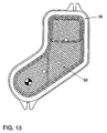
- Fig. 13
- eine Aufsicht eines Schnorchelflansches mit Sieb.
- Fig. 1
- a perspective view obliquely from below of a support structure for a crankcase for the attachment of a secondary shaft,
- Fig. 2
- 1 shows a perspective view of a support structure installed in a reciprocating piston internal combustion engine, with a crank mechanism shown in part without a crankcase,
- Fig. 3
- 2 shows an end side view of FIG. 2,
- Fig. 4
- 3 shows a side view of FIG. 3,
- Fig. 5
- a capsule device according to the invention in a view from below,
- Fig. 6
- FIG. 5 shows a part of a sectional view along the line VI-VI of FIG. 5,
- Fig. 7
- 4 shows a section along the line VII-VII of FIG. 5,
- Fig. 8
- 4 shows a section along the line VIII-VIII of FIG. 5,
- Fig. 9
- 5 shows a side view in the direction S of FIG. 5,
- Fig. 10
- 7 shows a detailed view of section F from FIG. 7,
- Fig. 11
- 7 shows a detailed view of section E of FIG. 7,
- Fig. 12
- a detailed view of section C of Fig. 8 and
- Fig. 13
- a top view of a snorkel flange with sieve.
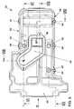
Die Figuren 1 bis 4 zeigen zur Erläuterung Teile eines Kurbeltriebes einer Brennkraftmaschine
mit einer unter einem Kurbelgehäuse an einer Stützstruktur 3 angeordneten, als
Ausgleichswelle 20 ausgebildeten Nebenwelle.Figures 1 to 4 show parts of a crank mechanism of an internal combustion engine for explanation
with a arranged under a crankcase on a
Die Hubkolben-Brennkraftmaschine weist ein nicht gezeigtes Kurbelgehäuse mit einer darin
rotierend gelagerten Kurbelwelle 1 auf. Seitliche Wandungen des Kurbelgehäuses sind über
die Kurbelwellenmitte 2 hinaus in Richtung auf eine nicht gezeigte Ölwanne bis in eine
Flanschebene E geführt. An dieser Flanschebene E schließt in Richtung auf die Ölwanne ein
an die Wandungen des Kurbelgehäuses angebundenes, insgesamt mit 3 bezeichnetes
Bauteil an, welches nachfolgend als Stützstruktur 3 bezeichnet wird. Dieses ist im wesentlichen
plattenartig ausgebildet und erstreckt sich in Längsrichtung L und Querrichtung Q des
Kurbelgehäuses und trennt durch seine Anbindung an den den Öffnungsbereich des Kurbelgehäuses
umgebenden Flansch den insgesamt mit 4 bezeichneten Kurbeltrieb gegenüber
der Ölwanne im wesentlichen ab.The reciprocating piston internal combustion engine has a crankcase, not shown, with one therein
rotating
Die dem Kurbeltrieb 4 zugewandte Fläche der Stützstruktur 3 ist zumindest im Bereich von
Kurbelwangen 6 des Kurbeltriebes 4 entsprechend der dort durch die Rotation entstehenden
Pleuelgeigenstruktur ausgebildet.The surface of the
Auf seiner vom Kurbeltrieb 4 abgewandten und der Ölwanne zugewandten Fläche 7 trägt die
Stützstruktur 3 einstückig und materialeinheitlich ausgebildete, jeweils ein ungeteiltes Lager
8 und 9 aufweisende Lagerböcke 10 und 11.On its
Die Stützstruktur 3 ist im wesentlichen rechteckförmig ausgebildet, wobei an Längsseiten 12
und 13 Befestigungsaugen 14 zur Durchführung von Schraubverbindungen angeordnet sind.
Die Längsseite 12 ist hierbei in der Darstellung von Fig. 1 im wesentlichen verdeckt. Mit den
Schraubverbindungen ist die Stützstruktur 3 in der Flanschebene E am Kurbelgehäuse festgelegt.The
In Längsrichtung L erstrecken sich zwischen den Längsseiten 12 und 13 endseitig jeweils
Stirnseiten 15 und 16. Die eine Stirnseite 15 ist als Stirnwandung 17 ausgebildet und nimmt
unter anderem integral den Lagerbock 10 auf.In the longitudinal direction L, each end extends between the
Im bestückten Zustand der Stützstruktur 3 gemäß Figuren 2, 3 und 4 ist in den Lagern 8 und
9 eine insgesamt mit 20 bezeichnete Nebenwelle drehbar gehalten. Diese ist integral und
einstückig mit einer Ausgleichsmasse 21 versehen und von der Stirnseite 16 aus zunächst
durch das Lager 9 und anschließend durch das Lager 8 gesteckt. Auf einen im eingesteckten
Zustand das Lager 8 durchsetzenden, abgesetzten Zapfen 22 der Nebenwelle 20
ist ein als Kettenrad ausgebildetes Antriebsrad 23 und anschließend eine weitere Ausgleichsmasse
24 aufgesetzt. Diese Anordnung gewährleistet gemeinsam mit einem an der
Innenseite der Stirnwandung 17 anliegenden Bund 26 der Nebenwelle 20 eine Axiallagerung,
während das Lager 9 als Loslager ausgebildet ist.In the assembled state of the
Die fliegende Lagerung der Ausgleichsmasse 21 gewährleistet ein bauraumoptimales Heranrücken
dieser Ausgleichsmasse 21 an die Stützstruktur 3. Diese weist in einem Abschnitt 7a
entsprechend geformte Konturflächen 27 zur Schaffung eines Freiganges auf.The floating mounting of the balancing
Zwischen den beiden Lagerböcken 10 und 11 sind sich kreuzende Versteifungsrippen 30
angeordnet, welche sich in Kreuzungspunkten 31 schneiden.Crossing stiffening
Der Antrieb der Nebenwelle 20 erfolgt von einem Abtriebsrad 40 der Kurbelwelle 1 aus.
Dieses Abtriebsrad 40 definiert gemeinsam mit dem Antriebsrad 23 eine Triebebene T für
eine Kette 41. Wie am besten aus Figuren 2 und 3 ersichtlich, treibt die Kette 41 mit ihrer
Rückseite zur Drehrichtungsumkehr die Nebenwelle 20 an. Zu diesem Zwecke sind zwei
Umlenkräder 42 vorgesehen, wobei eines dieser Umlenkräder 42 in einer Lagerung 43 der
Stirnwandung 17 drehbar gehalten ist. Ein weiteres Umlenkrad 42 wirkt als Antriebsrad für
eine nicht gezeigte Ölpumpe der Hubkolben-Brennkraftmaschine. Diese ist zur optimalen
Bauraumausnutzung zwischen der Innenseite 25 der Stirnwandung 17, der Fläche 7 und
neben der Nebenwelle 20 liegend lösbar an der Stützstruktur 3 angeordnet. Die Fläche 7
trägt zu diesem Zwecke Befestigungspunkte 44. The
Zur Versorgung der Lager 8 und 9 mit Schmieröl und zur Vermeidung von externen Zuleitungen,
weist die Stützstruktur 3 ein Kanalsystem für Schmieröl auf. Von der Flanschebene
E ausgehend erstreckt sich im Bereich des Lagerbockes 11 ein im wesentlichen
querlaufender Zuströmkanal 45, welcher sich bis zum dortigen Lager 9 erstreckt. In einem
von der Fläche 7 abragend ausgebildeten Schacht 46 erstreckt sich parallel zur Nebenwelle
20 ein den Zuströmkanal 45 schneidender Versorgungskanal 47, der das eingespeiste
Schmieröl zum Lager 8 fördert. Der den Versorgungskanal 47 aufnehmende Schacht 46
verläuft entlang einer Reihe von Kreuzungspunkten 31.To supply
Wie am besten aus Figur 1 ersichtlich, trägt die Fläche 7 weiterhin einen Steg 32, an
welchem eine im nachfolgenden beschriebene erfindungsgemäße Kapselvorrichtung der
Antriebswelle 20 angrenzt. Dieser Steg 32 erstreckt sich von der Stirnwand 17 ausgehend
beabstandet und parallel zur Längsseite 13 entlang der Stirnseite 16 und wiederum nach
innen versetzt im wesentlichen parallel zur anderen Längsseite 12. Im Bereich dieser
Längsseiten 12 und 13 sind zwischen diesen dem Steg 32 fensterartige Öffnungen 33 für
den Durchtritt von Schmieröl des Kurbeltriebes 4 in die Ölwanne angeordnet.As can best be seen from FIG. 1, the
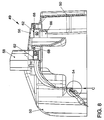
Figur 5 bis 9 zeigen die vorerwähnte erfindungsgemäße Kapselvorrichtung 49 in einer
bevorzugten Ausführungsform. Diese umfaßt ein wannenartiges Gehäuse 50, welches in
einer Umfangskontur und in einem in Figur 5 nur teilweise sichtbaren umlaufenden Wannenrand
64 der Kontur des Steges 32 von Figur 4 derart angepaßt ist, daß es am Steg 32
anflanschbar ist und die Nebenwelle 20 gegen eine Ölwanne kapselt. Die Kapselvorrichtung
49 umfaßt ferner in der dargestellten bevorzugten Ausführungsform Befestigungsaugen 52,
Clipverbinder 54, einen Schnorchelflansch mit Deckel 56, einen Schnorchel 58 und eine
Ölansaugöffnung 60.5 to 9 show the
Figur 6 zeigt detailliert den Bereich der Ölansaugöffnung 60, welcher neben dem
Schnorchelflansch mit Deckel 56 zusätzlich ein Sieb 62 umfaßt. Der Deckel 56 mit dem in
Figur 6 nicht sichtbaren Schnorchel 58 ist ölwannenseitig, d. h. in Einbaulage unterhalb der
Kapselvorrichtung 49 angeordnet. An einer gegenüberliegenden, dem Kurbelgehäuse bzw.
der Stützstruktur 3 zugewandten Seite in einem Innenraum der Kapselvorrichtung 49 ist ein
einstückig mit dem Gehäuse 50 ausgebildeter Anschlußstutzen 66 vorgesehen. Bei der
Montage der Kapselvorrichtung 49 an der Stützstruktur 3 wirkt dieser Anschlußstutzen 66
mit einem Ansaugstutzen 67 der Ölpumpe derart zusammen, daß die Ölpumpe mit dem
Schnorchel 58 verbunden ist und aus einem Ölsumpf Öl pumpt und fördert. Der Anschlußstutzen
66 und die Ölpumpe bzw. deren Ansaugstutzen 67 sind derart angeordnet, daß
diese Verbindung automatisch durch Aufsetzten der Kapselvorrichtung 49 hergestellt wird.
Zusätzliche Montagearbeiten zum Anschluß der Ölpumpe entfallen demnach. Zugleich wirkt
der Ansaugstutzen 67 als Zentrierung für das Gehäuse 50. Bei der Montage wird zunächst
das Sieb 62 in die Ölansaugöffnung 60 ein- und der Deckel 56 aufgelegt. Letzterer stößt in
diesem Montagestadium an eine um die Ölansaugöffnung 60 umlaufende Erhebung 68 an
und ist dementsprechend vom Sieb 62 beabstandet. In einem nachfolgenden Bearbeitungsschritt
wird der Deckel 56 auf die Erhebung 68 reibgeschweißt, wodurch die Erhebung
68 teilweise schmilzt und der Deckel 56 in Figur 6 nach unten wandert, bis er auf dem Sieb
66 aufliegt. Weiteres Reibschweißen verbindet nunmehr den Deckel 56 mit dem Sieb 66 und
dem Gehäuse 50 am Umfang des Siebes 66 innerhalb der Erhebung 68. Dieses zweistufige
Reibschweißen gewährleistet eine sichere, feste und dichte Verbindung im Bereich der
Ölansaugöffnung 60.
In Figur 7 ist der Schnorchel 58 in ausgezogenen Linien für eine bestimmte Brennkraftmaschine
gezeigt, während ein verkürzter Schnorchel 58 für eine bestimmte Brenkraftmaschine
mit einem anderen Hubvolumen und/oder einer anderen Einbaulage gestrichelt dargestellt
ist.FIG. 6 shows in detail the area of the
In FIG. 7, the
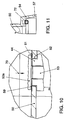
Figur 10 zeigt eine Detaildarstellung eines Befestigungsauges 52 am Gehäuse 50. Zum
Befestigen der Kapselvorrichtung 49 wird ölwannenseitig in Pfeilrichtung 70 eine Schraube
53 durch das Befestigungsauge 52 durchgeführt und kurbelgehäuseseitig entweder am
Kurbelgehäuse oder an den Befestigungspunkten 44 (Figur 1) der Stützstruktur 3 festgeschraubt.
Ein integral mit dem Gehäuse 50 ausgebildeter Ringsteg 59 in einer Einsenkung
61 wird durch Anlage des Schraubenkopfes 53 a plastisch verpreßt und macht einen
separaten Dichtring überflüssig. Das Schraubendrehmoment stützt sich am Kurbelgehäuse
oder am Leiterrahmen ab, nicht jedoch am Gehäuse 50. Dadurch tritt kein selbständiges
Lösen durch Kriechen des Gehäusewerkstoffes auf.FIG. 10 shows a detailed illustration of a
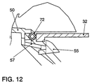
Die in Figuren 11 und 12 im Detail dargestellten Clipverbinder 54 könne zusätzlich zu den
Befestigungsaugen 52 oder statt diesen vorgesehen sein. Der Clipverbinder 54 umfaßt ein
hakenförmiges Element 55, welches über einen elastischen Arm 57 am Gehäuse 50 befestigt
ist. Beim Aufschieben auf den Steg 32 umgreift das hakenförmige Element 55 den
Steg 32, wie in Figur 12 dargestellt, und befestigt so das Gehäuse 50 in einer vorbestimmten
Position unterhalb des Kurbelgehäuses. Eine eingelegte Dichtschnur 72 dichtet das Gehäuse
50 an einer umlaufenden Auflagefläche auf dem Steg 32 gegen den Innenraum der
umgebenden Ölwanne ab. Die Clipverbindungen 54 haben den Vorteil, daß sie genauso
einfach und schnell wieder zu lösen sind, wie sie vorher durch "aufclipsen" des Gehäuses 50
hergestellt wurden. So ist die Kapselvorrichtung 49 auch einfach und schnell wieder zu
demontieren, beispielsweise für spätere Wartungs- oder Reparaturarbeiten.The
Fig. 13 zeigt den Deckel 56 mit Sieb 62 in vergrößerter Darstellung in einer Ansicht von der
Kurbelgehäuseseite her. Das Sieb 62 ist bevorzugt in einem vorbestimmten Winkel verkippt
zur Ölwanne bzw. zum in dieser enthaltenen Ölsumpf angeordnet, so daß das von der
Pumpe über das Sieb 62 geförderte Öl am Sieb 62 entlang eine vergrößerte Siebfläche
überwinden muß. Auf diese Weise wird das geförderte Öl von Luftblasen befreit, die sich auf
dem Sieb 62 abscheiden.Fig. 13 shows the
Die Kapselvorrichtung 49 verhindert in vorteilhafter Weise ein "panschen" der sich drehenden
Nebenwelle 20 im Ölsumpf, was zu einem unerwünschten Aufschäumen des Öls und
unnötiger Verlustarbeit führen würde. Der in die Kapselvorrichtung 49 integrierte Saugschnorchel
58 für die Ölpumpe reduziert die Gesamtzahl der Teile bei der Montage der
Brennkraftmaschine. Die Kapselvorrichtung 49 nimmt beispielsweise nur zur Nebenwelle 20
zu ihrer Schmierung gefördertes Öl auf und das vom Kurbeltrieb abströmende Öl wird bei
einer derartigen Ausführungsform vollständig an der Nebenwelle 20 vorbei in die Ölwanne
geleitet.The
Claims (17)
eine wannenförmige Kapselvorrichtung (49) mit einer offenen Seite, einem Gehäuse (50) und einen um die offene Seite umlaufenden Wannenrand (64) vorgesehen ist, welche mit der offenen Seite in Richtung Kurbelgehäuse und die Nebenwelle umschließend und gegen die Ölwanne abkapselnd, in der Ölwanne angeordnet ist.Arrangement for encapsulating a secondary shaft of a reciprocating piston internal combustion engine with a crankcase and an oil pan arranged on the crankcase, characterized in that
a trough-shaped capsule device (49) is provided with an open side, a housing (50) and a trough rim (64) surrounding the open side, which with the open side encircling the crankcase and the auxiliary shaft and encapsulating it against the oil pan, in which Oil pan is arranged.
dadurch gekennzeichnet, daß
an der Kapselvorrichtung (49) kurbelgehäuseseitig Befestigungsmittel (52, 54) ausgebildet sind.Arrangement according to claim 1,
characterized in that
Fastening means (52, 54) are formed on the capsule device (49) on the crankcase side.
dadurch gekennzeichnet, daß
die Befestigungsmittel Befestigungsaugen (52) sind, durch welche Schrauben (53) hindurchsteckbar und kurbelgehäuseseitig festschraubbar sind.Arrangement according to claim 2,
characterized in that
the fastening means are fastening eyes (52), through which screws (53) can be inserted and screwed tight on the crankcase side.
dadurch gekennzeichnet, daß
die Befestigungsmittel wenigstens einen Clipverschluß (54) umfassen.Arrangement according to claim 2,
characterized in that
the fastening means comprise at least one clip closure (54).
dadurch gekennzeichnet, daß
die Befestigungsmittel (52, 54) an dem Wannenrand (64) ausgebildet sind.Arrangement according to one of claims 2 to 4,
characterized in that
the fastening means (52, 54) are formed on the tub rim (64).
dadurch gekennzeichnet, daß
die Kapselvorrichtung (49) am Gehäuse (50) eine Ölansaugöffnung (60) aufweist, welche derart angeordnet ist, daß bei montierter Kapselvorrichtung (49) kurbelgehäuseseitig ein Ansaugstutzen einer Ölpumpe mit dieser Ölansaugöffnung (60) verbunden ist.Arrangement according to one of the preceding claims,
characterized in that
the capsule device (49) has an oil suction opening (60) on the housing (50), which is arranged such that when the capsule device (49) is mounted, an intake port of an oil pump is connected to this oil suction opening (60) on the crankcase side.
dadurch gekennzeichnet, daß
die Ölansaugöffnung (60) mit einem Sieb (62) versehen ist.Arrangement according to claim 6,
characterized in that
the oil suction opening (60) is provided with a sieve (62).
dadurch gekennzeichnet, daß
die Ölansaugöffnung (60) ölwannenseitig einen Schnorchel (58) aufweist, welcher in einen Ölsumpf in der Ölwanne ragt.Arrangement according to claim 6 or 7,
characterized in that
the oil intake opening (60) on the oil pan side has a snorkel (58) which projects into an oil sump in the oil pan.
dadurch gekennzeichnet, daß
ölwannenseitig an der Ölansaugöffnung (60) ein Schnorchelstutzen mit Deckel (56) angeordnet ist.Arrangement according to one of claims 6 to 9,
characterized in that
On the oil pan side of the oil intake opening (60) there is a snorkel with a cover (56).
dadurch gekennzeichnet, daß
das Kurbelgehäuse ölwannenseitig einen von einem äußeren Rand des Kurbelgehäuses beabstandeten, umlaufenden Steg (32) aufweist, wobei eine Kontur des Wannenrandes (64) der Kapselvorrichtung (49) im wesentlichen diesem Steg (32) folgt, so daß die Kapselvorrichtung (49) an diesen Steg (32) anflanschbar ist.Arrangement according to one of the preceding claims,
characterized in that
the crankcase on the oil pan side has a circumferential web (32) spaced from an outer edge of the crankcase, a contour of the tub edge (64) of the capsule device (49) essentially following this web (32), so that the capsule device (49) on it Web (32) can be flanged.
dadurch gekennzeichnet, daß
zwischen Kapselvorrichtung (49) und Kurbelgehäuse eine Stützstruktur (3) vorgesehen ist, welche eine als Ausgleichswelle (20) ausgebildete Nebenwelle trägt. Arrangement according to one of the preceding claims,
characterized in that
A support structure (3) is provided between the capsule device (49) and the crankcase, which supports a secondary shaft designed as a balancer shaft (20).
dadurch gekennzeichnet, daß
die Stützstruktur (3) ölwannenseitig einen von einem äußeren Rand der Stützstruktur beabstandeten, umlaufend Steg (32) aufweist, wobei eine Kontur des Wannenrandes (64) der Kapselvorrichtung (49) im wesentlichen diesem Steg (32) folgt, so daß die Kapselvorrichtung (49) an diesen Steg (32) anflanschbar ist.Arrangement according to claim 12,
characterized in that
the support structure (3) on the oil pan side has a circumferential web (32) spaced from an outer edge of the support structure, a contour of the tub rim (64) of the capsule device (49) essentially following this web (32) so that the capsule device (49 ) can be flanged to this web (32).
dadurch gekennzeichnet, daß
an der Kapselvorrichtung (49) vorgesehene Befestigungsmittel (54) auf diesen Steg (32) aufschnappen.Arrangement according to claim 13,
characterized in that
Snap the fastening means (54) provided on the capsule device (49) onto this web (32).
dadurch gekennzeichnet, daß
die Kapselvorrichtung (49) im Gehäuse (50) wenigstens eine Ölablauföffnung aufweist.Arrangement according to one of the preceding claims,
characterized in that
the capsule device (49) has at least one oil drain opening in the housing (50).
dadurch gekennzeichnet, daß
die Kapselvorrichtung (49) einstückig als Spritzgußteil ausgebildet ist.Arrangement according to one of the preceding claims,
characterized in that
the capsule device (49) is formed in one piece as an injection molded part.
dadurch gekennzeichnet, daß
eine Anordnung zum Einkapseln der Nebenwelle gemäß wenigstens einem der vorhergehenden Ansprüche vorgesehen ist.Internal combustion engine with a countershaft,
characterized in that
an arrangement for encapsulating the auxiliary shaft is provided according to at least one of the preceding claims.
Applications Claiming Priority (2)
| Application Number | Priority Date | Filing Date | Title |
|---|---|---|---|
| DE19741448 | 1997-09-19 | ||
| DE19741448A DE19741448A1 (en) | 1997-09-19 | 1997-09-19 | Arrangement for encapsulating a secondary shaft of a reciprocating piston internal combustion engine |
Publications (2)
| Publication Number | Publication Date |
|---|---|
| EP0903474A1 true EP0903474A1 (en) | 1999-03-24 |
| EP0903474B1 EP0903474B1 (en) | 2002-07-10 |
Family
ID=7842989
Family Applications (1)
| Application Number | Title | Priority Date | Filing Date |
|---|---|---|---|
| EP98117181A Expired - Lifetime EP0903474B1 (en) | 1997-09-19 | 1998-09-10 | Device for encapsulating a countershaft of a combustion engine |
Country Status (2)
| Country | Link |
|---|---|
| EP (1) | EP0903474B1 (en) |
| DE (2) | DE19741448A1 (en) |
Cited By (2)
| Publication number | Priority date | Publication date | Assignee | Title |
|---|---|---|---|---|
| WO2005003526A1 (en) * | 2003-07-02 | 2005-01-13 | Mtu Friedrichshafen Gmbh | Cover plate for a crankcase |
| CN110259885A (en) * | 2019-06-26 | 2019-09-20 | 浙江吉利控股集团有限公司 | A kind of balance system of engine for vehicle |
Citations (5)
| Publication number | Priority date | Publication date | Assignee | Title |
|---|---|---|---|---|
| EP0291358A2 (en) * | 1987-05-15 | 1988-11-17 | Honda Giken Kogyo Kabushiki Kaisha | Internal combustion engine |
| DE4204522C1 (en) | 1992-02-15 | 1993-04-15 | Mercedes-Benz Aktiengesellschaft, 7000 Stuttgart, De | IC engine silencer with lower cover shell - has oil flow shell aperture opening into noise damping chamber |
| EP0634566A1 (en) | 1993-07-12 | 1995-01-18 | Dr.Ing.h.c. F. Porsche Aktiengesellschaft | Device for guiding lubricant in an internal combustion engine |
| US5535643A (en) * | 1993-11-12 | 1996-07-16 | General Motors Corporation | Anti-rattle engine balancer which drives associated oil pump |
| EP0809041A2 (en) * | 1996-05-20 | 1997-11-26 | Audi Ag | Means for equilibration of inertial torque in internal combustion engines |
Family Cites Families (4)
| Publication number | Priority date | Publication date | Assignee | Title |
|---|---|---|---|---|
| DE3321751A1 (en) * | 1983-06-16 | 1984-12-20 | Dr.Ing.H.C. F. Porsche Ag, 7000 Stuttgart | COMBUSTION ENGINE FOR VEHICLES, ESP. FOR MOTORCYCLES |
| US4677948A (en) * | 1986-05-29 | 1987-07-07 | Chrysler Motors Corporation | Lubricating system for an engine balancing device |
| JPH0211418A (en) * | 1988-06-29 | 1990-01-16 | Honda Motor Co Ltd | Drive device for vehicle |
| US5479886A (en) * | 1995-05-12 | 1996-01-02 | Cummins Engine | Engine oil capacitor |
-
1997
- 1997-09-19 DE DE19741448A patent/DE19741448A1/en not_active Withdrawn
-
1998
- 1998-09-10 DE DE59804711T patent/DE59804711D1/en not_active Expired - Lifetime
- 1998-09-10 EP EP98117181A patent/EP0903474B1/en not_active Expired - Lifetime
Patent Citations (5)
| Publication number | Priority date | Publication date | Assignee | Title |
|---|---|---|---|---|
| EP0291358A2 (en) * | 1987-05-15 | 1988-11-17 | Honda Giken Kogyo Kabushiki Kaisha | Internal combustion engine |
| DE4204522C1 (en) | 1992-02-15 | 1993-04-15 | Mercedes-Benz Aktiengesellschaft, 7000 Stuttgart, De | IC engine silencer with lower cover shell - has oil flow shell aperture opening into noise damping chamber |
| EP0634566A1 (en) | 1993-07-12 | 1995-01-18 | Dr.Ing.h.c. F. Porsche Aktiengesellschaft | Device for guiding lubricant in an internal combustion engine |
| US5535643A (en) * | 1993-11-12 | 1996-07-16 | General Motors Corporation | Anti-rattle engine balancer which drives associated oil pump |
| EP0809041A2 (en) * | 1996-05-20 | 1997-11-26 | Audi Ag | Means for equilibration of inertial torque in internal combustion engines |
Cited By (3)
| Publication number | Priority date | Publication date | Assignee | Title |
|---|---|---|---|---|
| WO2005003526A1 (en) * | 2003-07-02 | 2005-01-13 | Mtu Friedrichshafen Gmbh | Cover plate for a crankcase |
| CN100443699C (en) * | 2003-07-02 | 2008-12-17 | Mtu腓特烈港有限责任公司 | Crankcase cover plate |
| CN110259885A (en) * | 2019-06-26 | 2019-09-20 | 浙江吉利控股集团有限公司 | A kind of balance system of engine for vehicle |
Also Published As
| Publication number | Publication date |
|---|---|
| EP0903474B1 (en) | 2002-07-10 |
| DE59804711D1 (en) | 2002-08-14 |
| DE19741448A1 (en) | 1999-03-25 |
Similar Documents
| Publication | Publication Date | Title |
|---|---|---|
| DE19619977C2 (en) | Oil pan for an internal combustion engine | |
| DE3226189C2 (en) | ||
| DE19639928C2 (en) | water pump | |
| DE60024738T2 (en) | Balancer housing | |
| DE3240237A1 (en) | FOUR-STOCK COMBUSTION ENGINE | |
| DE69907786T2 (en) | Internal combustion engine with anti-foam device | |
| DE2920081C2 (en) | Internal combustion engine, the engine carrier of which is supported on the crankcase by means of force-transmitting and structure-borne noise insulating elements | |
| EP0809041A2 (en) | Means for equilibration of inertial torque in internal combustion engines | |
| DE102011003003B4 (en) | Timing chain housing structure for engine | |
| DE19630545A1 (en) | Oil pump sprocket cover for an internal combustion engine | |
| DE19804135A1 (en) | Wiper bearing | |
| DE2423383A1 (en) | FLUID CIRCULATION PUMP | |
| DE102005061475A1 (en) | Water pump for mounting on a cylinder crankcase on a motor vehicle's internal combustion engine has a casing, an impeller wheel turning on bearings in the casing and graduated gearing | |
| EP0903474B1 (en) | Device for encapsulating a countershaft of a combustion engine | |
| DE3005728A1 (en) | CLUTCH | |
| DE19947271C2 (en) | Multi-cylinder internal combustion engine with at least one first balance shaft | |
| WO2008049525A1 (en) | Internal combustion engine having a cylinder crankcase and a v-shaped cylinder configuration | |
| DE102009025453B4 (en) | Balance shaft module | |
| DE2908434A1 (en) | HEAT PUMP DRIVE UNIT WITH A COMPRESSOR AND INTERNAL COMBUSTION ENGINE | |
| EP1164262B1 (en) | Oil module for combustion engine | |
| DE19632024C2 (en) | Oil pump for an internal combustion engine | |
| EP1582775A1 (en) | Transmission housing | |
| DE3942448A1 (en) | Cover plate for crankshaft opening in crankcase - is held in place by clamping strip with elastic intermediate layer | |
| DE19610872C1 (en) | Crank case for internal combustion engine | |
| DE4202161C2 (en) |
Legal Events
| Date | Code | Title | Description |
|---|---|---|---|
| PUAI | Public reference made under article 153(3) epc to a published international application that has entered the european phase |
Free format text: ORIGINAL CODE: 0009012 |
|
| AK | Designated contracting states |
Kind code of ref document: A1 Designated state(s): DE ES FR GB IT SE |
|
| AX | Request for extension of the european patent |
Free format text: AL;LT;LV;MK;RO;SI |
|
| 17P | Request for examination filed |
Effective date: 19990924 |
|
| AKX | Designation fees paid |
Free format text: DE ES FR GB IT SE |
|
| 17Q | First examination report despatched |
Effective date: 20010704 |
|
| GRAG | Despatch of communication of intention to grant |
Free format text: ORIGINAL CODE: EPIDOS AGRA |
|
| GRAG | Despatch of communication of intention to grant |
Free format text: ORIGINAL CODE: EPIDOS AGRA |
|
| GRAG | Despatch of communication of intention to grant |
Free format text: ORIGINAL CODE: EPIDOS AGRA |
|
| GRAH | Despatch of communication of intention to grant a patent |
Free format text: ORIGINAL CODE: EPIDOS IGRA |
|
| GRAH | Despatch of communication of intention to grant a patent |
Free format text: ORIGINAL CODE: EPIDOS IGRA |
|
| GRAA | (expected) grant |
Free format text: ORIGINAL CODE: 0009210 |
|
| AK | Designated contracting states |
Kind code of ref document: B1 Designated state(s): DE ES FR GB IT SE |
|
| REG | Reference to a national code |
Ref country code: GB Ref legal event code: FG4D Free format text: NOT ENGLISH |
|
| REF | Corresponds to: |
Ref document number: 59804711 Country of ref document: DE Date of ref document: 20020814 |
|
| GBT | Gb: translation of ep patent filed (gb section 77(6)(a)/1977) |
Effective date: 20020902 |
|
| PG25 | Lapsed in a contracting state [announced via postgrant information from national office to epo] |
Ref country code: SE Free format text: LAPSE BECAUSE OF FAILURE TO SUBMIT A TRANSLATION OF THE DESCRIPTION OR TO PAY THE FEE WITHIN THE PRESCRIBED TIME-LIMIT Effective date: 20021010 |
|
| ET | Fr: translation filed | ||
| PG25 | Lapsed in a contracting state [announced via postgrant information from national office to epo] |
Ref country code: ES Free format text: LAPSE BECAUSE OF FAILURE TO SUBMIT A TRANSLATION OF THE DESCRIPTION OR TO PAY THE FEE WITHIN THE PRESCRIBED TIME-LIMIT Effective date: 20030130 |
|
| PLBE | No opposition filed within time limit |
Free format text: ORIGINAL CODE: 0009261 |
|
| STAA | Information on the status of an ep patent application or granted ep patent |
Free format text: STATUS: NO OPPOSITION FILED WITHIN TIME LIMIT |
|
| 26N | No opposition filed |
Effective date: 20030411 |
|
| PGFP | Annual fee paid to national office [announced via postgrant information from national office to epo] |
Ref country code: GB Payment date: 20070822 Year of fee payment: 10 |
|
| PGFP | Annual fee paid to national office [announced via postgrant information from national office to epo] |
Ref country code: IT Payment date: 20070913 Year of fee payment: 10 |
|
| PGFP | Annual fee paid to national office [announced via postgrant information from national office to epo] |
Ref country code: FR Payment date: 20070904 Year of fee payment: 10 |
|
| GBPC | Gb: european patent ceased through non-payment of renewal fee |
Effective date: 20080910 |
|
| REG | Reference to a national code |
Ref country code: FR Ref legal event code: ST Effective date: 20090529 |
|
| PG25 | Lapsed in a contracting state [announced via postgrant information from national office to epo] |
Ref country code: IT Free format text: LAPSE BECAUSE OF NON-PAYMENT OF DUE FEES Effective date: 20080910 |
|
| PG25 | Lapsed in a contracting state [announced via postgrant information from national office to epo] |
Ref country code: FR Free format text: LAPSE BECAUSE OF NON-PAYMENT OF DUE FEES Effective date: 20080930 |
|
| PG25 | Lapsed in a contracting state [announced via postgrant information from national office to epo] |
Ref country code: GB Free format text: LAPSE BECAUSE OF NON-PAYMENT OF DUE FEES Effective date: 20080910 |
|
| PGFP | Annual fee paid to national office [announced via postgrant information from national office to epo] |
Ref country code: DE Payment date: 20140930 Year of fee payment: 17 |
|
| REG | Reference to a national code |
Ref country code: DE Ref legal event code: R119 Ref document number: 59804711 Country of ref document: DE |
|
| PG25 | Lapsed in a contracting state [announced via postgrant information from national office to epo] |
Ref country code: DE Free format text: LAPSE BECAUSE OF NON-PAYMENT OF DUE FEES Effective date: 20160401 |