EP0903394B1 - Verfahren zur gleichzeitigen Hydrierung von Diolefinen und Nitrilen mit Mehr-Reaktionsgefäss-Einheiten - Google Patents
Verfahren zur gleichzeitigen Hydrierung von Diolefinen und Nitrilen mit Mehr-Reaktionsgefäss-Einheiten Download PDFInfo
- Publication number
- EP0903394B1 EP0903394B1 EP98117746A EP98117746A EP0903394B1 EP 0903394 B1 EP0903394 B1 EP 0903394B1 EP 98117746 A EP98117746 A EP 98117746A EP 98117746 A EP98117746 A EP 98117746A EP 0903394 B1 EP0903394 B1 EP 0903394B1
- Authority
- EP
- European Patent Office
- Prior art keywords
- catalyst
- hydrogenation activity
- carried out
- reactor zone
- reactor
- Prior art date
- Legal status (The legal status is an assumption and is not a legal conclusion. Google has not performed a legal analysis and makes no representation as to the accuracy of the status listed.)
- Expired - Lifetime
Links
- 238000005984 hydrogenation reaction Methods 0.000 title claims description 92
- 150000001993 dienes Chemical class 0.000 title claims description 53
- 238000000034 method Methods 0.000 title claims description 51
- 150000002825 nitriles Chemical class 0.000 title claims description 22
- 239000003054 catalyst Substances 0.000 claims description 119
- IJGRMHOSHXDMSA-UHFFFAOYSA-N Atomic nitrogen Chemical compound N#N IJGRMHOSHXDMSA-UHFFFAOYSA-N 0.000 claims description 55
- 230000000694 effects Effects 0.000 claims description 49
- 239000001257 hydrogen Substances 0.000 claims description 37
- 229910052739 hydrogen Inorganic materials 0.000 claims description 37
- UFHFLCQGNIYNRP-UHFFFAOYSA-N Hydrogen Chemical compound [H][H] UFHFLCQGNIYNRP-UHFFFAOYSA-N 0.000 claims description 35
- 229910052757 nitrogen Inorganic materials 0.000 claims description 28
- 238000006243 chemical reaction Methods 0.000 claims description 25
- 229930195733 hydrocarbon Natural products 0.000 claims description 24
- 150000002430 hydrocarbons Chemical class 0.000 claims description 24
- 230000001172 regenerating effect Effects 0.000 claims description 24
- 238000011010 flushing procedure Methods 0.000 claims description 22
- 239000011261 inert gas Substances 0.000 claims description 22
- 239000004215 Carbon black (E152) Substances 0.000 claims description 20
- 239000002184 metal Substances 0.000 claims description 17
- 229910052751 metal Inorganic materials 0.000 claims description 17
- 239000007789 gas Substances 0.000 claims description 12
- 229910021536 Zeolite Inorganic materials 0.000 claims description 8
- 150000002739 metals Chemical class 0.000 claims description 8
- 239000010457 zeolite Substances 0.000 claims description 8
- 239000000463 material Substances 0.000 claims description 7
- XKRFYHLGVUSROY-UHFFFAOYSA-N Argon Chemical compound [Ar] XKRFYHLGVUSROY-UHFFFAOYSA-N 0.000 claims description 6
- 229910052799 carbon Inorganic materials 0.000 claims description 5
- 239000000203 mixture Substances 0.000 claims description 5
- OKTJSMMVPCPJKN-UHFFFAOYSA-N Carbon Chemical compound [C] OKTJSMMVPCPJKN-UHFFFAOYSA-N 0.000 claims description 4
- ATUOYWHBWRKTHZ-UHFFFAOYSA-N Propane Chemical compound CCC ATUOYWHBWRKTHZ-UHFFFAOYSA-N 0.000 claims description 4
- 239000002131 composite material Substances 0.000 claims description 4
- HNPSIPDUKPIQMN-UHFFFAOYSA-N dioxosilane;oxo(oxoalumanyloxy)alumane Chemical compound O=[Si]=O.O=[Al]O[Al]=O HNPSIPDUKPIQMN-UHFFFAOYSA-N 0.000 claims description 4
- VNWKTOKETHGBQD-UHFFFAOYSA-N methane Chemical compound C VNWKTOKETHGBQD-UHFFFAOYSA-N 0.000 claims description 4
- 229910052786 argon Inorganic materials 0.000 claims description 3
- 239000001307 helium Substances 0.000 claims description 3
- 229910052734 helium Inorganic materials 0.000 claims description 3
- SWQJXJOGLNCZEY-UHFFFAOYSA-N helium atom Chemical compound [He] SWQJXJOGLNCZEY-UHFFFAOYSA-N 0.000 claims description 3
- OTMSDBZUPAUEDD-UHFFFAOYSA-N Ethane Chemical compound CC OTMSDBZUPAUEDD-UHFFFAOYSA-N 0.000 claims description 2
- 239000001294 propane Substances 0.000 claims description 2
- 238000011069 regeneration method Methods 0.000 description 26
- 230000008929 regeneration Effects 0.000 description 25
- 230000009849 deactivation Effects 0.000 description 3
- 230000001934 delay Effects 0.000 description 3
- 239000000356 contaminant Substances 0.000 description 2
- 150000002431 hydrogen Chemical class 0.000 description 2
- 229930195734 saturated hydrocarbon Natural products 0.000 description 2
- RWSOTUBLDIXVET-UHFFFAOYSA-N Dihydrogen sulfide Chemical compound S RWSOTUBLDIXVET-UHFFFAOYSA-N 0.000 description 1
- PXHVJJICTQNCMI-UHFFFAOYSA-N Nickel Chemical compound [Ni] PXHVJJICTQNCMI-UHFFFAOYSA-N 0.000 description 1
- NINIDFKCEFEMDL-UHFFFAOYSA-N Sulfur Chemical compound [S] NINIDFKCEFEMDL-UHFFFAOYSA-N 0.000 description 1
- XLYOFNOQVPJJNP-PWCQTSIFSA-N Tritiated water Chemical compound [3H]O[3H] XLYOFNOQVPJJNP-PWCQTSIFSA-N 0.000 description 1
- 150000001875 compounds Chemical class 0.000 description 1
- 238000011109 contamination Methods 0.000 description 1
- 230000007423 decrease Effects 0.000 description 1
- 230000003247 decreasing effect Effects 0.000 description 1
- 239000007788 liquid Substances 0.000 description 1
- 150000002829 nitrogen Chemical class 0.000 description 1
- 229910052717 sulfur Inorganic materials 0.000 description 1
- 239000011593 sulfur Substances 0.000 description 1
Images


Classifications
-
- B—PERFORMING OPERATIONS; TRANSPORTING
- B01—PHYSICAL OR CHEMICAL PROCESSES OR APPARATUS IN GENERAL
- B01J—CHEMICAL OR PHYSICAL PROCESSES, e.g. CATALYSIS OR COLLOID CHEMISTRY; THEIR RELEVANT APPARATUS
- B01J29/00—Catalysts comprising molecular sieves
- B01J29/90—Regeneration or reactivation
-
- B—PERFORMING OPERATIONS; TRANSPORTING
- B01—PHYSICAL OR CHEMICAL PROCESSES OR APPARATUS IN GENERAL
- B01J—CHEMICAL OR PHYSICAL PROCESSES, e.g. CATALYSIS OR COLLOID CHEMISTRY; THEIR RELEVANT APPARATUS
- B01J38/00—Regeneration or reactivation of catalysts, in general
- B01J38/04—Gas or vapour treating; Treating by using liquids vaporisable upon contacting spent catalyst
- B01J38/10—Gas or vapour treating; Treating by using liquids vaporisable upon contacting spent catalyst using elemental hydrogen
-
- C—CHEMISTRY; METALLURGY
- C10—PETROLEUM, GAS OR COKE INDUSTRIES; TECHNICAL GASES CONTAINING CARBON MONOXIDE; FUELS; LUBRICANTS; PEAT
- C10G—CRACKING HYDROCARBON OILS; PRODUCTION OF LIQUID HYDROCARBON MIXTURES, e.g. BY DESTRUCTIVE HYDROGENATION, OLIGOMERISATION, POLYMERISATION; RECOVERY OF HYDROCARBON OILS FROM OIL-SHALE, OIL-SAND, OR GASES; REFINING MIXTURES MAINLY CONSISTING OF HYDROCARBONS; REFORMING OF NAPHTHA; MINERAL WAXES
- C10G45/00—Refining of hydrocarbon oils using hydrogen or hydrogen-generating compounds
- C10G45/32—Selective hydrogenation of the diolefin or acetylene compounds
- C10G45/34—Selective hydrogenation of the diolefin or acetylene compounds characterised by the catalyst used
Definitions
- the invention relates to a process for simultaneous selective hydrogenation of diolefins and nitriles from a hydrocarbon feedstock.
- the US-A-5,523,271 discloses a catalyst useful for the simultaneous and selective hydrogenation of diolefins and nitriles present in a hydrocarbon feedstock.
- the support material is preferably selected from the group consisting of an inorganic oxide-zeolite composite, carbon and zeolite.
- a catalytically active phase is deposited on the support material.
- the catalytically active metal phase is selected from the group consisting of partially reduced Group IB metals and completely reduced Group VIII metals.
- the catalytically active metal phase is present in an amount of ⁇ 0.03 wt %.
- a process for simultaneous selective hydrogenation of diolefins and nitriles from a hydrocarbon feedstock comprises the steps of: (a) providing a hydrocarbon feedstock having a diolefin content of greater than or equal to 0.1 wt% and a nitrile content of greater than or equal to 2 ppm; (b) providing at least a first and second reactor zone each containing a catalyst comprising a support material selected from the group consisting of inorganic oxide-zeolite composite, carbon and zeolite, and a catalytically active metal phase selected from the group consisting of partially reduced group IB metals and completely reduced group VIII metals, said metal phase being present in an amount of greater than or equal to 0.03 wt%, said catalyst having an initial diolefin hydrogenation activity and said catalyst in said second reactor zone having a reduced diolefin hydrogenation activity; (c) mixing said feedstock with hydrogen to provide a reaction feedstock having a ratio of hydrogen to di
- the process as set forth above is preferably carried out until said spent diolefin hydrogenation activity is reduced to not less than 50% of initial diolefin hydrogenation activity, at which point the flushing and regenerating steps carried out and repeated as desired.
- the process includes regenerating the hydrogenation catalyst to a hydrogenation activity of at least 90% of the initial diolefin hydrogenation activity of the catalyst.
- the invention relates to a process for regenerating a spent hydrogenation catalyst, preferably in a hydrogenation reactor, so as to avoid the necessity of catalyst removal and/or replacement, and also to a process for simultaneous and selective hydrogenation of a C4/C5 feedstock using multiple reactor zones and the process for regeneration.
- a preferred catalyst for simultaneous and selective hydrogenation of diolefins and nitriles present in a hydrocarbon feedstock comprises a support material preferably selected from the group consisting of an inorganic oxide-zeolite composite, carbon and zeolite, with a catalytically active phase deposited on the support material which is preferably selected from the group consisting of partially reduced group IB metals and completely reduced group VIII metals, wherein the catalytically active metal phase is preferably present in an amount of greater than or equal to 0.03 wt%.
- a hydrogenation catalyst used for treating a hydrocarbon feedstock having diolefins and nitriles for example greater than or equal to 0.1% diolefin and greater than or equal to 2 ppm nitrile, is monitored, particularly with respect to the activity of the catalyst toward the desired hydrogenation reactions.
- the feed of hydrocarbon to the catalyst material is temporarily interrupted, and the deactivated catalyst is treated first by flushing with an inert gas so as to remove traces of hydrocarbon from the catalyst, and then with a reducing gas in a regenerating step so as to provide a regenerated catalyst having a regenerated hydrogenation activity.
- catalyst as set forth above may be provided in a plurality of reactors or reactor zones such as adsorption-reactive units and the like, and hydrogenation can be carried out in a first reactor zone while the regeneration process of the present invention is carried out, preferably substantially simultaneously, in a second or different reactor zone.
- one reactor zone can be used for processing feedstock while the other is regenerated, and vice versa, thereby avoiding periods of down time during the regeneration process.
- the treatment or flushing of the catalyst with inert gas is preferably carried out using an inert gas selected from the group consisting of nitrogen, helium, argon, methane, ethane, propane, hydrogen or other light saturated hydrocarbon and mixtures thereof, preferably nitrogen, helium, argon and light saturated hydrocarbon, and most preferably nitrogen.
- Flushing the deactivated catalyst with inert gas in accordance with the invention advantageously serves to remove traces of hydrocarbons from the catalyst and to thereby provide a flushed catalyst which can then be regenerated by hydrogen flushing in accordance with the invention. It should be noted that this gas is said to be inert with respect to the catalyst.
- the catalyst is then preferably further flushed during a regeneration step with reducing gas such as hydrogen so as to recover a large portion, preferably at least about 90%, of original or initial catalyst activity.
- reducing gas such as hydrogen
- the flushing and regenerating steps using inert gas and reducing gas are preferably carried out in the hydrogenation reactor so that the catalyst to be regenerated does not need to be removed therefrom. Further, and advantageously, the flushing and regenerating steps of the present invention are carried out at temperatures and pressures in the reactor which are similar to the hydrogenation reaction, so as to provide a still further reduced interruption or disruption in the hydrogenation reaction.
- the hydrogenation reaction is typically carried out in a reactor, generally referred to in the drawings by reference numeral 10.
- the hydrogenation catalyst is disposed within reactor 10.
- a reaction feedstock comprising the feedstock to be treated and a hydrogen source are fed to reactor 10 as schematically illustrated by arrow A.
- the reaction feedstock is contacted with the hydrogenation catalyst in reactor 10 so as to provide a hydrogenated product exiting reactor 10 as shown by arrow B.
- reaction feedstock is fed to reactor 10 in an up-flow direction.
- nitrogen is fed to reactor 10 as schematically illustrated by arrow C in an opposite direction of flow with respect to feed, namely a down-flow direction. Nitrogen is shown exiting reactor 10 at arrow D.
- Nitrogen flow in accordance with the invention is conducted so as to remove traces of hydrocarbons from the hydrogenation catalyst within reactor 10, thereby preparing the catalyst for a subsequent regeneration step in accordance with the invention.
- Nitrogen is preferably flushed through reactor 10 at a space velocity and surface velocity sufficient to remove such traces of hydrocarbon.
- nitrogen may preferably be fed to reactor 10 at a space velocity of between 100 to 1000 h -1 , preferably 500 h -1 as measured at standard pressure, and temperature conditions.
- Nitrogen is also preferably fed at a surface velocity of between 50 to 150 m/min as measured at standard pressure, and temperature conditions.
- Nitrogen flow is preferably carried out in the reactor at a temperature of less than 300°C, preferably between 150°C to 300°C, and most preferably between 200°C to 290°C.
- hydrogen flow is preferably introduced in the direction schematically illustrated as arrow E, and exits reactor 10 in a direction of arrow F.
- Hydrogen flow is preferably carried out under reactor pressure and temperature conditions similar to those of the hydrogenation reaction.
- hydrogen flow is carried out at a pressure of 10.3 to 44.8 bars (150-650 psig), preferably between 13.79 to 20.685 bars (200 to about 300 psig) a temperature of between 100-300°C, and at a space velocity of between 20 h -1 and 200 h -1 .
- Hydrogen is preferably passed through reactor 10 so as to expose the hydrogenation catalyst therein to between 5 to 20 times the amount of hydrogen required to totally reduce the metal phase of the hydrogenation catalyst.
- this advantageously results in the regeneration of the hydrogenation catalyst within reactor 10 to a regenerated hydrogenation activity of at least 90% of the original activity.
- hydrogen flow in the direction of arrows E-F is stopped, and reactor 10 is again placed on line by again feeding reaction feedstock along arrow A so as to obtain hydrated or otherwise treated feedstock at the reactor exit as shown in arrow B.
- the regeneration process is preferably carried out in the reactor at similar temperature and pressure conditions to those of the hydrogenation process.
- a typical hydrogenation process may be carried out at temperatures of between 60 to 160°C or higher, and pressures of between 13,79 to 27,58 bars (200 to 400 psig).
- the regeneration process can be started as soon as feed to the reactor is stopped without requiring delays for adjusting temperature or pressure in the reactor.
- the inert gas or nitrogen flushing step in accordance with the invention is critical in obtaining regeneration of the hydrogenation catalyst in accordance with the invention. Also as set forth above, it has been found to be advantageous to flow the nitrogen and hydrogen sequentially in opposite directions to one another so as to provide enhanced regeneration of the hydrogenation catalyst. In this regard, and as illustrated in FIG. 1, nitrogen flow may therefore be carried out in a direction opposite to normal feed, while hydrogen is carried out in a direction parallel to normal feed. Of course, the direction of nitrogen and hydrogen flow could be reversed, if desired, in accordance with the invention.
- a first reactor 20 and a second reactor 22 may suitably be provided, and connected to a source 24 of feedstock, a source 26 of hydrogen, a source 28 of inert gas.
- each reactor or reactor zone, 20, 22, is provided with catalyst in accordance with the present invention as described above.
- flow from source 24 of feedstock is preferably controlled so as to direct a feedstock hydrogen mixture or reaction feedstock to reactor zone 20 for treatment in the presence of catalyst in accordance with the present invention, while flow is also controlled through reactor zone 22 so as to first flush catalyst in reactor zone 22 with an inert gas, and then further flush or expose reactor zone 22 to a regenerating flow of hydrogen in accordance with the regeneration process of the present invention.
- catalyst in reactor zone 22 is being regenerated as discussed above, such that, advantageously, when catalyst in reactor zone 20 is deactivated to the point to where it is to be regenerated, flow of reaction feedstock can be diverted to reactor zone 22 and regenerated catalyst contained therein, while catalyst in reactor zone 20 is regenerated through flushing with inert gas and then with hydrogen in accordance with the present invention.
- reactor zones 20, 22 are shown connected to sources 24, 26 and 28 of reaction feedstock, hydrogen and inert gas through a series of lines and valves adapted to control flow so as to alternatingly direct reaction feedstock to one reactor zone while the other zone is regenerated.
- FIG. 5 shows, the valves in an open/closed position for providing flow of reaction feedstock to reactor zone 20, and for providing flow of regenerating hydrogen to reactor zone 22. Operation in accordance with the present invention would be carried out in this configuration until catalyst in reactor zone 22 is sufficiently regenerated, and catalyst in reactor zone 20 is deactivated to the point it must be regenerated, at which time reaction feedstock is redirected to reactor zone 22, and inert gas followed by hydrogen are directed to reactor zone 20.
- this sequence could be carried out alternatingly so as to provide for substantially continuous and non-interrupted hydrogenation.
- FIG. 5 provides an illustration of one configuration for carrying out the process, and numerous other configurations as well as more reactors or reactor zones could be employed.
- a 500 cc sample of nickel catalyst such as that described in U.S. Patent No. 5,523,271 was loaded in a packed bed reactor of a pilot plant unit.
- a feedstock was provided which was a C 5 naphtha cut having the composition as set forth in Table 1 below.
- the feedstock was mixed with hydrogen in a 2.8:1 molar ratio and fed up-flow to the pilot plant reactor. Hydrogenation is then carried out as set forth in U.S. Patent No. 5,663,446. After 115 hours of operation, the conversion or activity for diolefin hydrogenation had decreased by less than about 5% of the original initial total conversion. At this point, the naphtha feed to the reactor was stopped, and a regeneration procedure in accordance with the present invention was commenced.
- nitrogen was passed through the reactor in a down-flow direction, opposite to the flow of feedstock.
- the nitrogen was flowed through the reactor at a space velocity measured at standard conditions of 450 h -1 , and a surface velocity of 1500 cm/min, at room temperature for about 3 hours.
- This nitrogen flow advantageously had the effect of unbinding hydrocarbons from the surface of the hydrogenation catalyst.
- nitrogen flow was stopped and a hydrogen flow was introduced into the reactor, in an up-flow direction, at a space velocity of 50 h -1 .
- the hydrogen was fed through the reactor at a temperature of 200°C for 24 hours.
- the regeneration process according to the present invention was complete and the bed was restored to operation feeding a naphtha hydrogen reaction feedstock for treatment.
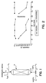
- the hydrogenation catalyst showed excellent regeneration in activity as shown in FIG. 2.
- Example 1 The catalyst of Example 1 was subjected to the same hydrogenation reaction conditions and feedstock as described in Example 1, but the regeneration process was started when the hydrogenation catalyst illustrated a diolefin hydrogenation activity of about 30% and nitrile hydrogenation activity which was almost totally deactivated, after 220 hours of operation.
- the catalyst so deactivated was regenerated according to the present invention as described in Example 1.
- FIG. 3 illustrates the excellent regeneration of the catalyst even after such extreme deactivation and contamination over in excess of 200 hours of operation.
- Example 2 The same catalyst as set forth in Example 1 was again subjected to the feedstock and hydrogenation reaction as described in Example 1.
- a hydrogen treatment was started without an initial nitrogen flushing so as to remove naphtha and other hydrocarbons from the catalyst bed.
- FIG. 4 illustrates the initial operation, Regeneration No. 1 in accordance with Example 2, and the subsequent Regeneration No. 2 using only hydrogen as described above.
- regeneration using hydrogen only, without an initial nitrogen flushing did not regenerate the hydrogenation catalyst.
- the nitrogen flushing step of the process of the present invention serves advantageously to provide excellent regeneration of a hydrogenation catalyst in accordance with the invention.
Landscapes
- Chemical & Material Sciences (AREA)
- Engineering & Computer Science (AREA)
- Chemical Kinetics & Catalysis (AREA)
- Organic Chemistry (AREA)
- Oil, Petroleum & Natural Gas (AREA)
- Materials Engineering (AREA)
- General Chemical & Material Sciences (AREA)
- Organic Low-Molecular-Weight Compounds And Preparation Thereof (AREA)
- Catalysts (AREA)
- Production Of Liquid Hydrocarbon Mixture For Refining Petroleum (AREA)
- Low-Molecular Organic Synthesis Reactions Using Catalysts (AREA)
Claims (14)
- Verfahren zur gleichzeitigen Hydrierung von Diolefinen und Nitrilen aus einer Kohlenwasserstoffbeschickung, bestehend aus den Schritten:(a) Bereitstellen einer Kohlenwasserstoffbeschickung mit einem Diolefingehalt von größer oder gleich 0,1 Gew.-% und einem Nitrilgehalt von größer oder gleich 2 ppm;(b) Bereitstellen zumindest einer ersten und einer zweiten Reaktorzone, die beide einen Katalysator enthalten, der aus einem Trägermaterial besteht, das aus der Gruppe bestehend aus einem anorganischen Oxid-Zeolith-Verbund, Kohlenstoff und Zeolith, ausgewählt wurde, sowie aus einer katalytisch wirksamen Metallphase, die aus der Gruppe bestehend aus teilweise reduzierten Metallen der Gruppe IB und vollständig reduzierten Metallen der Gruppe VIII ausgewählt wurde, wobei die Metallphase in einer Menge von größer oder gleich 0,03 Gew.-% vorhanden ist und der Katalysator eine anfängliche Diolefin-Hydrierwirksamkeit und der Katalysator in der zweiten Reaktorzone eine reduzierte Diolefin-Hydrierwirksamkeit aufweist;(c) Mischen der Beschickung mit Wasserstoff zum Bereitstellen einer Reaktionsbeschickung mit einem Verhältnis von Wasserstoff zu Diolefinen und Nitrilen von weniger als einer dreifachen stöchiometrischen Menge, die zur selektiven Hydrierung der Diolefine und der Nitrile erforderlich ist;(d) Behandeln der Reaktionsbeschickung in Anwesenheit des Katalysators in der ersten Reaktorzone bei einer Hydriertemperatur und unter einem Hydrierdruck, bis der Katalysator in der ersten Reaktorzone eine reduzierte Diolefin-Hydrierwirksamkeit von nicht weniger als 50% der anfänglichen Diolefin-Hydrieraktivität aufweist;(e) Spülen des Katalysators in der zweiten Reaktorzone mit einem Inertgas, so dass Kohlenwasserstoffspuren von diesem Katalysator entfernt werden und hierdurch ein gespülter Katalysator in der zweiten Reaktorzone bereitgestellt wird;(f) Regenerieren des gespülten Katalysators in der zweiten Reaktorzone durch weiteres Durchströmen des gespülten Katalysators mit einem Reduktionsgas zum Bereitstellen eines regenerierten Katalysators in der zweiten Reaktorzone, der eine regenerierte Diolefin-Hydrierwirksamkeit aufweist, die größer ist als die reduzierte Diolefin-Hydrierwirksamkeit;(g) Behandeln der Reaktionsbeschickung in Anwesenheit des Katalysators in der zweiten Reaktorzone bei einer Hydriertemperatur und einem Hydrierdruck, bis der Katalysator eine reduzierte Diolefin-Hydrierwirksamkeit von nicht weniger als 50% der anfänglichen Diolefin-Hydrierwirksamkeit aufweist;(h) Spülen des Katalysators in der ersten Reaktorzone mit einem Inertgas, um Kohlenwasserstoffspuren aus dem Katalysator zu entfernen und hierdurch einen gespülten Katalysator in der ersten Reaktorzone bereitzustellen;(i) Regenerieren des gespülten Katalysators in der ersten Reaktorzone durch weiteres Durchströmen des gespülten Katalysators mit einem Reduktionsgas, so dass ein regenerierter Katalysator in der ersten Reaktorzone mit einer regenerierten Diolefin-Hydrierwirksamkeit bereitgestellt wird, die größer ist als die reduzierte Diolefin-Hydrierwirksamkeit; und(j) Wiederholen der Schritte (d) bis (i).
- Verfahren nach Anspruch 1, dadurch gekennzeichnet, dass der Schritt des Regenerierens den regenerierten Katalysator bereitstellt, der eine regenerierte Diolefin-Hydrierwirksamkeit von zumindest 90% der anfänglichen Diolefin-Hydrierwirksamkeit aufweist.
- Verfahren nach Anspruch 1 oder 2, dadurch gekennzeichnet, dass der Schritt des Behandelns solange durchgeführt wird, bis die reduzierte Diolefin-Hydrierwirksamkeit nicht weniger als 50% des anfänglichen Wertes beträgt, vorzugsweise dadurch gekennzeichnet, dass der Schritt des Behandelns solange durchgeführt wird, bis die reduzierte Diolefin-Hydrierwirksamkeit nicht weniger als 80% des anfänglichen Wertes beträgt.
- Verfahren nach einem der Ansprüche 1 bis 3, dadurch gekennzeichnet, dass der Schritt des Behandelns das Zuführen der Kohlenwasserstoffbeschickung zum Katalysator in einer Zuführrichtung umfasst, dass der Schritt des Spülens durch Zuführen des Inertgases weitgehend entgegengesetzt zur Zuführrichtung durchgeführt wird, und dass der Schritt des Regenerierens durch Zuführen des Reduktionsgases in Zuführrichtung erfolgt.
- Verfahren nach einem der Ansprüche 1 bis 4, dadurch gekennzeichnet, dass der Schritt des Spülens und der Schritt des Regenerierens durch aufeinanderfolgendes Zuführen des Inertgases und des Reduktionsgases zum Katalysator in weitgehend entgegengesetzter Richtung erfolgt.
- Verfahren nach Anspruch 1, dadurch gekennzeichnet, dass die Schritte (e) und (f) weitgehend gleichzeitig mit dem Schritt (d) und die Schritte (h) und (i) weitgehend gleichzeitig mit Schritt (g) durchgeführt werden, wodurch der Katalysator in einer der ersten und der zweiten Reaktorzone gespült und regeneriert wird, während der Katalysator in der anderen der ersten und der zweiten Reaktorzone zur Behandlung der Reaktionsbeschickung verwendet wird.
- Verfahren nach einem der Ansprüche 1 bis 6, dadurch gekennzeichnet, dass der Schritt des Spülens mittels Inertgas bei einer Temperatur von weniger oder gleich 300°C, vorzugsweise im Bereich von unterhalb der Umgebungstemperatur bis 300°C, insbesondere bei einer Temperatur zwischen Raumtemperatur und 290°C durchgeführt wird.
- Verfahren nach einem der Ansprüche 1 bis 7, dadurch gekennzeichnet, dass das Inertgas aus der Gruppe, bestehend aus Stickstoff, Helium, Argon, Methan, Ethan, Propan, Wasserstoff und Mischungen daraus, ausgewählt wird, vorzugsweise dadurch, dass das Inertgas Stickstoff ist.
- Verfahren nach einem der Ansprüche 1 bis 8, dadurch gekennzeichnet, dass der Schritt des Regenerierens bei einer Temperatur von zwischen 100°C und 300°C durchgeführt wird.
- Verfahren nach einem der Ansprüche 1 bis 9, dadurch gekennzeichnet, dass der Schritt des Regenerierens bei einem Druck von zwischen 10,3425 und 44,8157 bar (150 bis 650 psi) durchgeführt wird.
- Verfahren nach einem der Ansprüche 1 bis 10, dadurch gekennzeichnet, dass der Schritt des Regenerierens das Spülen des gespülten Katalysators mit einer Menge an Reduktionsgas umfasst, die der 5- bis 20-fachen Menge an Reduktionsgas entspricht, welche zur weitgehend vollständigen Reduzierung der Metallphase des Katalysators ausreichend ist.
- Verfahren nach einem der Ansprüche 1 bis 11, dadurch gekennzeichnet, dass der Schritt des Spülens bei einer Raumgeschwindigkeit des Inertgases von zwischen 100 und 1000 h-1 durchgeführt wird.
- Verfahren nach einem der Ansprüche 1 bis 12, dadurch gekennzeichnet, dass der Schritt des Regenerierens bei einer Raumgeschwindigkeit des Reduktionsgases von zwischen 20 h-1 und 200 h-1 durchgeführt wird.
- Verfahren nach einem der Ansprüche 1 bis 13, dadurch gekennzeichnet, dass das Reduktionsgas Wasserstoff ist.
Applications Claiming Priority (2)
| Application Number | Priority Date | Filing Date | Title |
|---|---|---|---|
| US934030 | 1997-09-19 | ||
| US08/934,030 US5877364A (en) | 1994-12-13 | 1997-09-19 | Process for the simultaneous selective hydrogenation of diolefins and nitriles in multiple reactor units |
Publications (3)
| Publication Number | Publication Date |
|---|---|
| EP0903394A2 EP0903394A2 (de) | 1999-03-24 |
| EP0903394A3 EP0903394A3 (de) | 1999-03-31 |
| EP0903394B1 true EP0903394B1 (de) | 2003-01-02 |
Family
ID=25464839
Family Applications (1)
| Application Number | Title | Priority Date | Filing Date |
|---|---|---|---|
| EP98117746A Expired - Lifetime EP0903394B1 (de) | 1997-09-19 | 1998-09-18 | Verfahren zur gleichzeitigen Hydrierung von Diolefinen und Nitrilen mit Mehr-Reaktionsgefäss-Einheiten |
Country Status (5)
| Country | Link |
|---|---|
| US (1) | US5877364A (de) |
| EP (1) | EP0903394B1 (de) |
| BR (1) | BR9803489A (de) |
| DE (1) | DE69810407T2 (de) |
| ES (1) | ES2190022T3 (de) |
Families Citing this family (6)
| Publication number | Priority date | Publication date | Assignee | Title |
|---|---|---|---|---|
| CA2432205C (en) * | 2000-12-22 | 2010-03-16 | Europeenne De Retraitement De Catalyseurs Eurecat | Regeneration method of heterogeneous catalysts and adsorbents |
| WO2006125832A1 (es) | 2005-05-23 | 2006-11-30 | Repsol Ypf | Catalizador de níquel, procedimiento de obtención del mismo y uso |
| US8598060B2 (en) | 2006-07-31 | 2013-12-03 | Basf Se | Method of regenerating ruthenium catalysts for the ring hydrogenation of phthalates |
| US8350106B2 (en) * | 2008-06-30 | 2013-01-08 | Uop Llc | Selective hydrogenation of unsaturated aliphatic hydrocarbons in predominantly aromatic streams |
| CN102159532B (zh) | 2008-09-08 | 2014-09-17 | 三菱瓦斯化学株式会社 | 苯二甲胺的制备方法 |
| FR2984915B1 (fr) * | 2011-12-22 | 2016-07-15 | Ifp Energies Now | Procede d'hydrogenation selective de charges olefiniques avec des reacteurs permutables incluant au moins une etape de court-circuitage d'un reacteur |
Family Cites Families (5)
| Publication number | Priority date | Publication date | Assignee | Title |
|---|---|---|---|---|
| US4683052A (en) * | 1985-06-11 | 1987-07-28 | Mobil Oil Corporation | Method for non-oxidative hydrogen reactivation of zeolite dewaxing catalysts |
| DD273783A1 (de) * | 1988-07-06 | 1989-11-29 | Leuna Werke Veb | Verfahren zur in-situ-reaktivierung von pd-haltigen hydrierkatalysatoren |
| US5332705A (en) * | 1992-06-19 | 1994-07-26 | Exxon Chemical Patents Inc. | Regeneration of acetylene converter catalysts by hydrogen stripping |
| US5817589A (en) * | 1996-04-02 | 1998-10-06 | Intevep, S.A. | Regeneration of catalyst comprising flushing with inert gas followed by flushing with hydrogen |
| US5523271A (en) * | 1994-12-13 | 1996-06-04 | Intevep, S.A. | Catalyst for the simultaneous selective hydrogenation of diolefins and nitriles and method of making same |
-
1997
- 1997-09-19 US US08/934,030 patent/US5877364A/en not_active Expired - Lifetime
-
1998
- 1998-09-18 ES ES98117746T patent/ES2190022T3/es not_active Expired - Lifetime
- 1998-09-18 BR BR9803489-8A patent/BR9803489A/pt not_active IP Right Cessation
- 1998-09-18 DE DE69810407T patent/DE69810407T2/de not_active Expired - Lifetime
- 1998-09-18 EP EP98117746A patent/EP0903394B1/de not_active Expired - Lifetime
Also Published As
| Publication number | Publication date |
|---|---|
| EP0903394A2 (de) | 1999-03-24 |
| DE69810407T2 (de) | 2003-10-30 |
| EP0903394A3 (de) | 1999-03-31 |
| ES2190022T3 (es) | 2003-07-16 |
| DE69810407D1 (de) | 2003-02-06 |
| US5877364A (en) | 1999-03-02 |
| BR9803489A (pt) | 1999-12-07 |
Similar Documents
| Publication | Publication Date | Title |
|---|---|---|
| CA2175327C (en) | Regeneration of catalyst for the simultaneous selective hydrogenation of diolefins and nitriles | |
| JP4074668B2 (ja) | 単一ストリッパー槽における多段ストリッピングを伴う多段水素処理方法 | |
| JP4074667B2 (ja) | 単一反応槽における多段水素処理方法 | |
| JP3729621B2 (ja) | 接触分解ガソリンの水素化脱硫方法及びガソリン | |
| AU676844B2 (en) | Regeneration of acetylene converter catalysts by hydrogen stripping | |
| JP4798324B2 (ja) | 少なくとも3留分への分別により生じた重質フラクションおよび中間フラクションの脱硫を含むガソリンの脱硫方法 | |
| JP2003515658A (ja) | 触媒の還元を含む移動床での芳香族化合物の製造方法 | |
| JP4961093B2 (ja) | メルカプタンを除去するための接触ストリッピング | |
| EP0903394B1 (de) | Verfahren zur gleichzeitigen Hydrierung von Diolefinen und Nitrilen mit Mehr-Reaktionsgefäss-Einheiten | |
| US4752595A (en) | Catalyst pretreatment for regenerated noble metal on zeolite catalyst | |
| EP0255754B1 (de) | Methode der Olefinhydrierung | |
| US5306681A (en) | Method for recovery or maintaining the activity of hydroisomerization catalysts | |
| US20080029435A1 (en) | Rejuvenation process for olefin polymerization and alkylation catalyst | |
| CA1331864C (en) | Process for hydrotreating olefinic distillate | |
| KR100408211B1 (ko) | 선택적수소화반응및활성화점토를사용하여예비처리하는파라크실렌분리방법 | |
| EP0650516B1 (de) | Arsin als Moderator für die Acetylenumwandlung | |
| MXPA98007588A (en) | Process for the simultaneous selective hydrogenation of diolephins and nitrile in reactormultip units | |
| EP0629683B1 (de) | Verfahren zur Verbesserung einer Kohlenwasserstoffbeschickung | |
| EP1256559A1 (de) | Verfahren und Vorrichtung zur Reinigung einer Styrolbeschickung mit Verwendung eines Katalysators mit niedrigen Palladiumgehalt | |
| RU2117029C1 (ru) | Способ очистки продуктов каталитического риформинга от олефиновых углеводородов | |
| KR101300389B1 (ko) | 이원기능형 촉매의 연속재생 방법 |
Legal Events
| Date | Code | Title | Description |
|---|---|---|---|
| PUAI | Public reference made under article 153(3) epc to a published international application that has entered the european phase |
Free format text: ORIGINAL CODE: 0009012 |
|
| PUAL | Search report despatched |
Free format text: ORIGINAL CODE: 0009013 |
|
| AK | Designated contracting states |
Kind code of ref document: A2 Designated state(s): DE ES FI FR GB IT NL |
|
| AX | Request for extension of the european patent |
Free format text: AL;LT;LV;MK;RO;SI |
|
| AK | Designated contracting states |
Kind code of ref document: A3 Designated state(s): AT BE CH CY DE DK ES FI FR GB GR IE IT LI LU MC NL PT SE |
|
| AX | Request for extension of the european patent |
Free format text: AL;LT;LV;MK;RO;SI |
|
| RHK1 | Main classification (correction) |
Ipc: C10G 45/34 |
|
| 17P | Request for examination filed |
Effective date: 19990807 |
|
| AKX | Designation fees paid |
Free format text: DE ES FI FR GB IT NL |
|
| 17Q | First examination report despatched |
Effective date: 20011031 |
|
| GRAG | Despatch of communication of intention to grant |
Free format text: ORIGINAL CODE: EPIDOS AGRA |
|
| RIC1 | Information provided on ipc code assigned before grant |
Free format text: 7C 10G 45/34 A |
|
| GRAG | Despatch of communication of intention to grant |
Free format text: ORIGINAL CODE: EPIDOS AGRA |
|
| GRAH | Despatch of communication of intention to grant a patent |
Free format text: ORIGINAL CODE: EPIDOS IGRA |
|
| GRAH | Despatch of communication of intention to grant a patent |
Free format text: ORIGINAL CODE: EPIDOS IGRA |
|
| GRAA | (expected) grant |
Free format text: ORIGINAL CODE: 0009210 |
|
| AK | Designated contracting states |
Kind code of ref document: B1 Designated state(s): DE ES FI FR GB IT NL |
|
| REG | Reference to a national code |
Ref country code: GB Ref legal event code: FG4D Free format text: 20030102 |
|
| REF | Corresponds to: |
Ref document number: 69810407 Country of ref document: DE Date of ref document: 20030206 Kind code of ref document: P |
|
| REG | Reference to a national code |
Ref country code: ES Ref legal event code: FG2A Ref document number: 2190022 Country of ref document: ES Kind code of ref document: T3 |
|
| ET | Fr: translation filed | ||
| PLBE | No opposition filed within time limit |
Free format text: ORIGINAL CODE: 0009261 |
|
| STAA | Information on the status of an ep patent application or granted ep patent |
Free format text: STATUS: NO OPPOSITION FILED WITHIN TIME LIMIT |
|
| 26N | No opposition filed |
Effective date: 20031003 |
|
| REG | Reference to a national code |
Ref country code: FR Ref legal event code: PLFP Year of fee payment: 18 |
|
| PGFP | Annual fee paid to national office [announced via postgrant information from national office to epo] |
Ref country code: FI Payment date: 20150929 Year of fee payment: 18 Ref country code: ES Payment date: 20150928 Year of fee payment: 18 Ref country code: GB Payment date: 20150928 Year of fee payment: 18 |
|
| PGFP | Annual fee paid to national office [announced via postgrant information from national office to epo] |
Ref country code: FR Payment date: 20150917 Year of fee payment: 18 |
|
| PGFP | Annual fee paid to national office [announced via postgrant information from national office to epo] |
Ref country code: IT Payment date: 20150923 Year of fee payment: 18 |
|
| PGFP | Annual fee paid to national office [announced via postgrant information from national office to epo] |
Ref country code: DE Payment date: 20150929 Year of fee payment: 18 |
|
| PGFP | Annual fee paid to national office [announced via postgrant information from national office to epo] |
Ref country code: NL Payment date: 20150926 Year of fee payment: 18 |
|
| REG | Reference to a national code |
Ref country code: DE Ref legal event code: R119 Ref document number: 69810407 Country of ref document: DE |
|
| PG25 | Lapsed in a contracting state [announced via postgrant information from national office to epo] |
Ref country code: FI Free format text: LAPSE BECAUSE OF NON-PAYMENT OF DUE FEES Effective date: 20160918 |
|
| REG | Reference to a national code |
Ref country code: NL Ref legal event code: MM Effective date: 20161001 |
|
| GBPC | Gb: european patent ceased through non-payment of renewal fee |
Effective date: 20160918 |
|
| PG25 | Lapsed in a contracting state [announced via postgrant information from national office to epo] |
Ref country code: NL Free format text: LAPSE BECAUSE OF NON-PAYMENT OF DUE FEES Effective date: 20161001 |
|
| REG | Reference to a national code |
Ref country code: FR Ref legal event code: ST Effective date: 20170531 |
|
| PG25 | Lapsed in a contracting state [announced via postgrant information from national office to epo] |
Ref country code: FR Free format text: LAPSE BECAUSE OF NON-PAYMENT OF DUE FEES Effective date: 20160930 Ref country code: DE Free format text: LAPSE BECAUSE OF NON-PAYMENT OF DUE FEES Effective date: 20170401 Ref country code: GB Free format text: LAPSE BECAUSE OF NON-PAYMENT OF DUE FEES Effective date: 20160918 |
|
| PG25 | Lapsed in a contracting state [announced via postgrant information from national office to epo] |
Ref country code: IT Free format text: LAPSE BECAUSE OF NON-PAYMENT OF DUE FEES Effective date: 20160918 |
|
| REG | Reference to a national code |
Ref country code: ES Ref legal event code: FD2A Effective date: 20180507 |
|
| PG25 | Lapsed in a contracting state [announced via postgrant information from national office to epo] |
Ref country code: ES Free format text: LAPSE BECAUSE OF NON-PAYMENT OF DUE FEES Effective date: 20160919 |