EP0902965B1 - Lampe a reflexions multiples sans electrode, au soufre ou au selenium et procede pour obtenir une radiation avec une telle lampe - Google Patents
Lampe a reflexions multiples sans electrode, au soufre ou au selenium et procede pour obtenir une radiation avec une telle lampe Download PDFInfo
- Publication number
- EP0902965B1 EP0902965B1 EP97928997A EP97928997A EP0902965B1 EP 0902965 B1 EP0902965 B1 EP 0902965B1 EP 97928997 A EP97928997 A EP 97928997A EP 97928997 A EP97928997 A EP 97928997A EP 0902965 B1 EP0902965 B1 EP 0902965B1
- Authority
- EP
- European Patent Office
- Prior art keywords
- light
- fill
- lamp
- recited
- envelope
- Prior art date
- Legal status (The legal status is an assumption and is not a legal conclusion. Google has not performed a legal analysis and makes no representation as to the accuracy of the status listed.)
- Expired - Lifetime
Links
- NINIDFKCEFEMDL-UHFFFAOYSA-N Sulfur Chemical compound [S] NINIDFKCEFEMDL-UHFFFAOYSA-N 0.000 title claims description 25
- 239000011593 sulfur Substances 0.000 title claims description 24
- 229910052717 sulfur Inorganic materials 0.000 title claims description 24
- 239000011669 selenium Substances 0.000 title claims description 23
- 238000000034 method Methods 0.000 title claims description 21
- BUGBHKTXTAQXES-UHFFFAOYSA-N Selenium Chemical compound [Se] BUGBHKTXTAQXES-UHFFFAOYSA-N 0.000 title claims description 20
- 229910052711 selenium Inorganic materials 0.000 title claims description 20
- 230000005855 radiation Effects 0.000 title description 32
- 230000003287 optical effect Effects 0.000 claims abstract description 12
- 230000003595 spectral effect Effects 0.000 claims description 40
- 238000009826 distribution Methods 0.000 claims description 20
- VYPSYNLAJGMNEJ-UHFFFAOYSA-N silicon dioxide Inorganic materials O=[Si]=O VYPSYNLAJGMNEJ-UHFFFAOYSA-N 0.000 claims description 20
- 239000000463 material Substances 0.000 claims description 19
- 238000002310 reflectometry Methods 0.000 claims description 19
- PNEYBMLMFCGWSK-UHFFFAOYSA-N aluminium oxide Inorganic materials [O-2].[O-2].[O-2].[Al+3].[Al+3] PNEYBMLMFCGWSK-UHFFFAOYSA-N 0.000 claims description 10
- 239000000919 ceramic Substances 0.000 claims description 8
- 239000010453 quartz Substances 0.000 claims description 8
- 239000000843 powder Substances 0.000 claims description 6
- 239000000377 silicon dioxide Substances 0.000 claims description 5
- 239000000126 substance Substances 0.000 claims description 5
- 230000005284 excitation Effects 0.000 claims description 3
- 238000000576 coating method Methods 0.000 description 24
- 238000001228 spectrum Methods 0.000 description 23
- 239000011248 coating agent Substances 0.000 description 22
- 229910052714 tellurium Inorganic materials 0.000 description 12
- PORWMNRCUJJQNO-UHFFFAOYSA-N tellurium atom Chemical compound [Te] PORWMNRCUJJQNO-UHFFFAOYSA-N 0.000 description 12
- 239000011149 active material Substances 0.000 description 9
- 238000006243 chemical reaction Methods 0.000 description 7
- -1 tin halide Chemical class 0.000 description 6
- 230000009102 absorption Effects 0.000 description 5
- 238000010521 absorption reaction Methods 0.000 description 5
- 230000001464 adherent effect Effects 0.000 description 5
- 230000008878 coupling Effects 0.000 description 5
- 238000010168 coupling process Methods 0.000 description 5
- 238000005859 coupling reaction Methods 0.000 description 5
- 239000000835 fiber Substances 0.000 description 4
- 239000002245 particle Substances 0.000 description 3
- 239000007787 solid Substances 0.000 description 3
- PRPINYUDVPFIRX-UHFFFAOYSA-N 1-naphthaleneacetic acid Chemical compound C1=CC=C2C(CC(=O)O)=CC=CC2=C1 PRPINYUDVPFIRX-UHFFFAOYSA-N 0.000 description 2
- XKRFYHLGVUSROY-UHFFFAOYSA-N Argon Chemical compound [Ar] XKRFYHLGVUSROY-UHFFFAOYSA-N 0.000 description 2
- 239000013543 active substance Substances 0.000 description 2
- 150000001875 compounds Chemical class 0.000 description 2
- 238000010276 construction Methods 0.000 description 2
- 238000005336 cracking Methods 0.000 description 2
- 238000005286 illumination Methods 0.000 description 2
- 229910018162 SeO2 Inorganic materials 0.000 description 1
- 229910018219 SeTe Inorganic materials 0.000 description 1
- 229910052786 argon Inorganic materials 0.000 description 1
- 230000005540 biological transmission Effects 0.000 description 1
- 229910052794 bromium Inorganic materials 0.000 description 1
- 238000004891 communication Methods 0.000 description 1
- 229910052593 corundum Inorganic materials 0.000 description 1
- PXJJSXABGXMUSU-UHFFFAOYSA-N disulfur dichloride Chemical compound ClSSCl PXJJSXABGXMUSU-UHFFFAOYSA-N 0.000 description 1
- 235000012489 doughnuts Nutrition 0.000 description 1
- 230000000694 effects Effects 0.000 description 1
- 238000010891 electric arc Methods 0.000 description 1
- 229910052733 gallium Inorganic materials 0.000 description 1
- 239000007789 gas Substances 0.000 description 1
- XMBWDFGMSWQBCA-UHFFFAOYSA-N hydrogen iodide Chemical compound I XMBWDFGMSWQBCA-UHFFFAOYSA-N 0.000 description 1
- 229910052738 indium Inorganic materials 0.000 description 1
- 229910052743 krypton Inorganic materials 0.000 description 1
- DNNSSWSSYDEUBZ-UHFFFAOYSA-N krypton atom Chemical compound [Kr] DNNSSWSSYDEUBZ-UHFFFAOYSA-N 0.000 description 1
- 239000007788 liquid Substances 0.000 description 1
- 238000004519 manufacturing process Methods 0.000 description 1
- 229910001507 metal halide Inorganic materials 0.000 description 1
- 150000005309 metal halides Chemical class 0.000 description 1
- 238000000465 moulding Methods 0.000 description 1
- 229910052958 orpiment Inorganic materials 0.000 description 1
- 239000004482 other powder Substances 0.000 description 1
- 238000013021 overheating Methods 0.000 description 1
- 230000002093 peripheral effect Effects 0.000 description 1
- 230000010287 polarization Effects 0.000 description 1
- 238000009877 rendering Methods 0.000 description 1
- JPJALAQPGMAKDF-UHFFFAOYSA-N selenium dioxide Chemical compound O=[Se]=O JPJALAQPGMAKDF-UHFFFAOYSA-N 0.000 description 1
- LNBXMNQCXXEHFT-UHFFFAOYSA-N selenium tetrachloride Chemical compound Cl[Se](Cl)(Cl)Cl LNBXMNQCXXEHFT-UHFFFAOYSA-N 0.000 description 1
- FESBVLZDDCQLFY-UHFFFAOYSA-N sete Chemical compound [Te]=[Se] FESBVLZDDCQLFY-UHFFFAOYSA-N 0.000 description 1
- 238000005245 sintering Methods 0.000 description 1
- 150000003498 tellurium compounds Chemical class 0.000 description 1
- 229910052716 thallium Inorganic materials 0.000 description 1
- 229910001845 yogo sapphire Inorganic materials 0.000 description 1
- 229910000859 α-Fe Inorganic materials 0.000 description 1
Images


Classifications
-
- H—ELECTRICITY
- H01—ELECTRIC ELEMENTS
- H01J—ELECTRIC DISCHARGE TUBES OR DISCHARGE LAMPS
- H01J61/00—Gas-discharge or vapour-discharge lamps
- H01J61/02—Details
- H01J61/30—Vessels; Containers
- H01J61/35—Vessels; Containers provided with coatings on the walls thereof; Selection of materials for the coatings
-
- H—ELECTRICITY
- H01—ELECTRIC ELEMENTS
- H01J—ELECTRIC DISCHARGE TUBES OR DISCHARGE LAMPS
- H01J61/00—Gas-discharge or vapour-discharge lamps
- H01J61/02—Details
- H01J61/025—Associated optical elements
-
- H—ELECTRICITY
- H01—ELECTRIC ELEMENTS
- H01J—ELECTRIC DISCHARGE TUBES OR DISCHARGE LAMPS
- H01J61/00—Gas-discharge or vapour-discharge lamps
- H01J61/02—Details
- H01J61/12—Selection of substances for gas fillings; Specified operating pressure or temperature
-
- H—ELECTRICITY
- H01—ELECTRIC ELEMENTS
- H01J—ELECTRIC DISCHARGE TUBES OR DISCHARGE LAMPS
- H01J61/00—Gas-discharge or vapour-discharge lamps
- H01J61/02—Details
- H01J61/38—Devices for influencing the colour or wavelength of the light
-
- H—ELECTRICITY
- H01—ELECTRIC ELEMENTS
- H01J—ELECTRIC DISCHARGE TUBES OR DISCHARGE LAMPS
- H01J65/00—Lamps without any electrode inside the vessel; Lamps with at least one main electrode outside the vessel
- H01J65/04—Lamps in which a gas filling is excited to luminesce by an external electromagnetic field or by external corpuscular radiation, e.g. for indicating plasma display panels
- H01J65/042—Lamps in which a gas filling is excited to luminesce by an external electromagnetic field or by external corpuscular radiation, e.g. for indicating plasma display panels by an external electromagnetic field
- H01J65/044—Lamps in which a gas filling is excited to luminesce by an external electromagnetic field or by external corpuscular radiation, e.g. for indicating plasma display panels by an external electromagnetic field the field being produced by a separate microwave unit
Definitions
- the present invention is directed to method of generating visible light and to a discharge lamp as defined in the precharacterizing portions of claims 1 and 10, respectively.
- the present invention provides a method of generating visible light as defined in claim 1, and a discharge lamp as defined in claim 10 which eliminates or reduces the need for bulb rotation.
- the invention affords increased design flexibility in providing lamp bulbs of smaller dimensions and/or utilizing sulfur, selenium or tellurium fills having lower density of active substances than in the prior art, which are still capable of providing a primarily visible light output.
- This facilitates the provision of low power lamps, which may lend themselves to the use of smaller bulbs.
- This feature of the invention may be used in combination with other features, or independently. For example, a smaller bulb may be provided either which doesn't rotate, or which does rotate.
- the fill is excited to cause the sulfur or selenium to produce a spectral power component in the ultraviolet and a spectral power component in the visible region, wherein the multiple reflections result in a reduced ultraviolet spectral component having a magnitude of at least 50% less than the original component.
- a bulb which has a reflector layer around the quartz, except for an aperture through which the light exits.
- aperture lamps are known in the prior art, and an example is shown in U.S. Patent No. Re 34,492 to Roberts.
- U.S. Patent No. 4,071,798 describes a linear lamp for use in a copy machine.
- the lamp includes a light reflective coating defining a first aperture for a desired directional light output.
- the lamp further includes an infrared reflecting coating defining a second aperture for heat transmission.
- the Roberts patent discloses an electrodeless spherical envelope having a reflective coating thereon, except for an aperture which is in registry with a light guide.
- the Roberts structure is not suitable for practicing the method of the present invention as it would be employed in normal commercial use. This is because of its use of a coating on the lamp envelope. When the bulb heats up during use, the different thcrmal indices of expansion of the quartz envelope and the coating cause the coating to crack. Thus, the lifetime of the bulb is quite limited. Also, a coating is not normally thick enough to provide the degree of reflectivity which is required to provide adequate wavelength conversion from ultraviolet to visible.
- the covering comprises a jacket which unlike a coating, is non-adherent to the bulb.
- the jacket is made thick enough to provide high enough reflectivity to accomplish the desired wavelength conversion.
- the reflective bulb covering is made of the same material as the bulb, so that there is no problem with differential thermal expansion.
- the covering may additionally be in the form of a non-adherent jacket.
- a diffusely reflecting powder is disposed between a jacket and the bulb.
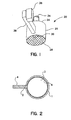
- FIG. 1 a prior art lamp having a fill which upon excitation contains sulfur, selenium, or tellurium, is depicted.
- the light provided is molecular radiation which is principally in the visible region of the spectrum.
- Lamp 20 includes a microwave cavity 24 which is comprised of metallic cylindrical member 26 and metallic mesh 28.
- Mesh 28 allows light to escape from the cavity while retaining most of the microwave energy inside.
- Bulb 30 is disposed in the cavity, which in the embodiment depicted is spherical.
- the bulb is supported by a stem, which is connected with motor 34 for effecting rotation of the bulb. The rotation promotes stable operation of the lamp.
- Microwave power is generated by magnetron 36, and waveguide 38 transmits such power to a slot (not shown) in the cavity wall, from where it is coupled to the cavity and particularly to the fill in bulb 30.
- Bulb 30 is comprised of a bulb envelope and a fill in the envelope.
- the fill contains sulfur, selenium, or tellurium, or an appropriate sulfur, selenium, or tellurium compound.
- InS, As 2 S 3 , S 2 Cl 2 , CS 2 , In 2 S 3 , SeS, SeO 2 , SeCl 4 , SeTe, SCe 2 , P 2 Se 5 , Se 3 As 2 , TeO, TeS, TeCl 5 , TeBr 5 , and TeI 5 may be used.
- Additional compounds which may be used are those which have a sufficiently low vapor pressure at room temperature, i.e., are a solid or a liquid, and which have a sufficiently high vapor pressure at operating temperature to provide useful illumination.
- the molecular spectra of these substances as generated by lamps known to the art were recognized to be primarily in the ultraviolet region.
- the radiation initially provided by the elemental sulfur, selenium, and/or tellurium (herein referred to as "active material") is similar to that in the prior art lamp, i.e., primarily in the ultraviolet region.
- active material the radiation initially provided by the elemental sulfur, selenium, and/or tellurium
- the radiation passes through the fill on its way to the envelope wall, it is converted by a process of absorption and re-emission into primarily visible radiation.
- the magnitude of the shift is directly related to the optical path length, i.e., the density of the active material in the fill multiplied by the diameter of the bulb. If a smaller bulb is used, a higher density of active material must be provided to efficiently produce the desired visible radiation while if a larger bulb is used, lower density of such substances may be used.
- the optical path length is greatly increased without increasing the diameter of the bulb by reflecting the radiation after it initially passes through the fill a multiplicity of times through the fill.
- the density of the active material and the bulb size are small enough so that the radiation which has initially passed through the fill and is being reflected may have a substantial spectral power component in the ultraviolet region. That is, in the absence of the multiple reflections, the spectrum which is emitted from the bulb might not be acceptable for use in a visible lamp. However, due to the multiple reflections, ultraviolet radiation is converted to visible, which produces a better spectrum. The multiple reflections through the fill permit the use of a smaller density of active material to provide an acceptable spectrum for any given application.
- the smaller density fill has reduced electrical impedance, which in many embodiments provides better microwave or R.F. coupling to the fill. Operation at such smaller density of active material promotes stable operation, even without bulb rotation. Furthermore the capability of using smaller bulbs increases design flexibility, and for example, facilitates the provision of low power lamps.
- microwave refers to a frequency band which is higher than that of "R.F.”.
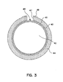
- a bulb having a reflective layer thereon except for an aperture, from which the light exits.
- a lamp of this type which is disclosed in Roberts Patent No. RE 34,492, is shown in Figure 2.
- spherical envelope or bulb 9 which is typically made of quartz contains a discharge forming fill 3.
- the envelope bears a reflective coating 1 around the entire surface except for aperture 2, which is in registry with light guide 4.
- the Roberts structure utilizes a coating which is by its nature adherent, (of a different material than the bulb) it is not suitable for practicing the method of the present invention.
- a coating which is by its nature adherent, (of a different material than the bulb) it is not suitable for practicing the method of the present invention.
- the bulb heats up during normal commercial use, the different thermal indices of expansion of the quartz envelope and the coating cause the coating to crack.
- the lifetime of the device is quite limited.
- a coating is not normally thick enough to provide the degree of reflectivity which is required to provide adequate wavelength conversion from ultraviolet to visible.
- Bulb 40 which encloses fill 42 is surrounded by non-adherent reflecting jacket 44.
- the jacket is made thick enough to provide high enough ultraviolet reflectivity to accomplish the desired wavelength conversion.
- There is an air gap 46 between the bulb and jacket which may be of the order of several thousandths of an inch.
- the jacket contacts the bulb at a minimum of one location, and may contact the bulb at multiple locations.
- a diffusely reflecting powder such as alumina or other powder may be used to fill in the gap between the jacket and the bulb.
- the gap may be somewhat wider.
- a reflective bulb covering of ceramic is used which is made of the same material as the bulb. Hence, there is no problem with differential thermal expansion. Such covering may also be constructed so that there is no adherence to the bulb.
- a sintered body is built up directly on the spherical bulb. It starts off as a powder, but is heated and pressurized so as to form a sintered solid. Since there is no adherence, when the jacket is cracked it will fall apart. Suitable materials are powdered alumina and silica, or combinations thereof.
- the jacket is made thick enough to provide the required UV and visible reflectivity as described herein and it is normally thicker than .5 mm and may be up to about 2 to 3 mm, which is much thicker than a coating.
- a jacket construction is illustrated in connection with Figures 4 and 5.
- the jacket is formed separately from the bulb.
- the quartz bulb is blow molded into a spherical form which results in a bulb that is dimensionally controlled for OD (outside diameter) and wall thickness.
- a filling tube is attached to the spherical bulb at the time of molding.
- a bulb of 7 mm OD and wall thickness of 0.5 mm filled with 0.05 mg Se and 500 Torr Xe has been operated in an inductivity coupled apparatus.
- the filling tube is removed so that only a short protrusion from the bulb remains.
- the jacket is formed of lightly sintered highly reflective alumina (Al 2 O 3 ) in two pieces 44A and 44B as indicated in the Figure.
- the particle size distribution and the crystalline structure of the jacket material must be capable of providing the desired optical properties.
- Alumina in powder form is sold by different manufacturers, and for example, alumina powder sold by Nichia America Corp. under the designation NP-999-42 may be suitable.
- the Figure is a cross-sectional view of the bulb, jacket, and aperture taken through the center of the bulb. The tip-off is not shown in the view.
- the ID (inside diameter) of the jacket is spherical in shape except the region near the tip-off, not shown.
- the partially sintered jacket is sintered to the degree that particle necking (attachment between the particles) can be observed on a micro-scale. The sintering is governed by the required thermal heat conductivity through the ceramic.
- the purpose of the necking is to enhance heat conduction while having minimal influence on the ceramic's reflectivity.
- the two halves of the ceramic are sized for a very close fit and can be held together by mechanical means or can be cemented using by way of example, the General Electric Arc Tube Coating No. 113-7-38.
- the jacket ID and bulb OD are chosen so that an average air gap allows adequate thermal heat conduction away from the bulb and the jacket thickness is chosen for required reflectivity. Bulbs have been operated with an air gap of several thousandths of an inch and a minimum ceramic thickness as thin as 1 mm.
- the material used for the bulb is quartz (SiO 2 ), and the reflective covering is silica (SiO 2 ). Since the materials are the same, there is no problem with differential thermal expansion.
- the silica is in amorphous form and is comprised of small pieces which are fused together lightly. It is made thick enough to achieve the desired reflectivity, and is white in color.
- the silica may also be applied in form of a non-adherent jacket.
- the material for jacket 44 in Figure 3 is highly reflective in the ultraviolet and visible, and has a low absorption over these ranges and preferably also in the infrared.
- the coating reflects substantially all of the ultraviolet and visible radiation incident on it, meaning that its reflectivity in both the ultraviolet and visible portions of the spectrum is greater than 85%, over the ranges (UV and visible) at least between 330 nm and 730 nm. Such reflectivity is preferably greater than 97%, and most preferably greater than 99%. Reflectivity is defined as the total fraction of incident radiative power returned over the above-mentioned wavelength ranges to the interior. High reflectivity is desirable because any loss in light is multiplied by the number of reflections.
- Jacket 10 is preferably a diffuse reflector of the radiation, but could also be a specular reflector.
- the jacket reflects incident radiation regardless of the angle of incidence.
- the above-mentioned reflectivity percentages preferably extend throughout wavelengths well below 330 nm, for example, down to 250 nm and most preferably down to 220 nm.
- the jacket is reflective in the infrared, so that the preferred material is highly reflective from the deep ultraviolet through the infrared.
- High infrared reflectivity is desirable because it improves the energy balance, and allows operation at lower power.
- the jacket must also be able to withstand the high temperatures which are generated in the bulb.
- alumina and silica are suitable materials and are present in the form of a jacket which is thick enough to provide the required reflectivity and structural rigidity.
- the multiple reflections of the radiation by the coating simulates the effect of a much larger bulb, permitting operation at a lower density of active material and/or with a smaller bulb.
- Each absorption and re-emission of an ensemble of photons including those corresponding to the substantial ultraviolet radiation which is reflected results in a shift of the spectral power to distribution towards longer wavelengths.
- the spectral shift will be limited by the vibrational temperature of the active species.
- aperture 48 in Figure 3 is depicted as being unjacketed, it is preferably provided with a substance which has a high ultraviolet reflectivity, but a high transparency to visible radiation.
- a substance which has a high ultraviolet reflectivity, but a high transparency to visible radiation is a multi-layer dielectric stack having the desired optical properties.
- the parameter alpha is defined as the ratio of the aperture surface area to the entire area of the reflective surface, including aperture area.
- Alpha can thus take on values between near zero for a very small aperture to 0.5 for a half coated bulb.
- the preferred alpha has a value in the range of 0.02 to 0.3 for many applications.
- the ratio alpha outside this range will also work but may be less effective, depending on the particular application. Smaller alpha values will typically increase brightness, reduce color temperature, and lower efficacy.
- an advantage of the invention is that a very bright light source can be provided.
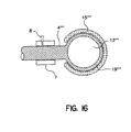
- FIG. 6 A further embodiment is shown in Figure 6, which utilizes a light port in the form of fiber optic 14 which interfaces with the aperture 12.
- the area of the aperture is considered to be the cross-sectional area of the port.
- diffusely reflecting jacket 10 surrounds bulb 19.
- the light port which interfaces with the aperture 12' is a compound parabolic reflector (CPC) 70.
- CPC compound parabolic reflector
- a CPC appears in cross-section as two parabolic members tilted towards each other at a tilt angle. It is effective to transform light having an angular distribution of from 0 to 90 degrees to a much smaller angular distribution, for example zero to ten degrees or less (a maximum of ten degrees from normal).
- the CPC can be either a reflector operating in air or a refractor using total internal reflection.
- the CPC may be arranged, for example, by coating the inside surface of a reflecting CPC so as to reflect the ultraviolet and visible light, while end surface 72 is provided which passes visible light, but which may be configured or coated to reflect unwanted components of the radiation back through the aperture.
- unwanted components may for example, and without limitation, include particular wavelength region(s), particular polarization(s) and spatial orientation of rays.
- Surface 72 is shown as a dashed line to connote that it both passes and reflects radiation.
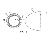
- Figure 8 is another embodiment utilizing a CPC.
- the bulb is the same as in Figure 7, whereas the light port is fiber optic 14", feeding CPC 70.
- less heat will reach the CPC than in the embodiment of Figure 7.
- a problem in the embodiments of Figures 6 to 8 is that there is an intersection between the bulb and the light port at which the light can escape.
- a fiber optic 80 is disposed in front of the diffusing orifice
- a solid or reflective optic 82 e.g. a CPC
- Light diffuses through the orifice and smoothly enters the fiber or other optic without encountering any abrupt intersections.
- the diameter of the optic may be larger, smaller, or about the same size as the diameter of the orifice.
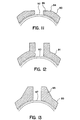
- FIGs 11 to 13 depict various orifice designs.
- the jacket 90 has orifice 92, wherein flat front surface 94 is present.
- the jacket 91 has orifice 93 having a length which extends beyond the jacket thickness.
- the jacket 95 has orifice 97 and graduated thickness area 98.
- the cross sectional shape of the orifice will typically be circular, but could be rectangular or have some other shape.
- the interior reflecting wall could be converging or diverging.
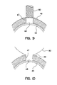
- a reflector 49 (96 in Figure 11) is shown.
- the reflector is placed in contact or nearly in contact with jacket 44, and its function is to reflect light leaking out at or near the interface in the vicinity of the orifice. While the reflector is optional, it is expected to improve performance. Light reflected back into the ceramic near the interface will primarily find its way back into the aperture or bulb unless lost by absorption.
- the radial dimension (in the case where the orifice has a circular cross-section the reflector would be donut shaped and the dimension would be "radial") of reflector 49 should be about the same or smaller than the height of orifice 47. It is preferably quartz coated with a dielectric stack in the visible.
- Figure 14 depicts an embodiment of the invention wherein ultraviolet/visible reflective coating 51 is located on the walls of metallic enclosure 52.
- bulb 50 which does not bear a reflective covering.
- a screen 54 which is also the aperture, completes the enclosure.
- the reflective surface constrains the light produced to exit through the screen area.
- the enclosure may be a microwave cavity and microwave excitation may be introduced, e.g., through a coupling slot in the cavity.
- microwave or R.F. power could be inductively applied, in which the case the enclosure would not have to be a resonant cavity, but could provide effective. shielding.
- FIG 15. An embodiment in which effective shielding is provided is shown in Figure 15.
- the bulb is similar to that described in connection with Figure 3, although in the particular embodiment illustrated it has a bigger alpha than is shown in Figure 3. It is powered by either microwave or R.F. power, which excites coupling coil 62 (shown in cross-section) which surrounds the bulb.
- a Faraday shield 60 surrounds the unit for electromagnetic shielding except for the area around light port 69. If necessary, lossy ferrite or other magnetic shielding material may be provided outside enclosure 60 to provide additional shielding. In other embodiments, other optical elements may be in communication with the aperture, in which case, the Faraday shield would enclose the device except for the area around such optical elements.
- the opening in the closed box is small enough so that it is beyond cutoff.
- the density of the active substance in the fill can vary from the same as standard values to very low density values.
- FIG. 16 depicts how this may be accomplished. Referring to the Figure, rotation is effected by an air turbine, so as not to block visible light. An air bearing 7 and air inlet 8 are shown and air from an air turbine (not shown) is fed to the inlet.
- the reflective media be located so as to reflect radiation through the fill a multiplicity of times.
- a dielectric reflector may be located to the exterior of the bulb.
- loss of light can be avoided by covering the slot with a dielectric reflective cover.
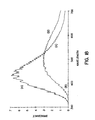
- Spectrum B is taken from the same bulb which has been coated so as to provide multiple reflections in accordance with an aspect of the present invention. It is seen that a larger proportion of the radiation is in the visible region in Spectrum B, and that the ultraviolet radiation is reduced by at least (more than) 50%.
- spectrum B as depicted in Figure 17 is suitable for some applications, it is possible to obtain spectra having even proportionately more visible and less ultraviolet by using coatings having higher reflectivity.
- the smaller the aperture the more relative visible output will be produced but the lower the efficacy.
- An advantage of the invention is that a bright source, for example which would be useful in some projection applications could be obtained by making the aperture very small. In this case, greater brightness would be obtained at lower efficacy.
- a spherical bulb made of quartz having an ID of 33 mm and an OD of 35 mm was filled with sulfur at a density of .43 mg/cc and 6666, 1184 Pa (50 torr) of argon.
- the bulbs used in Figures 17 to 20 were used only to demonstrate the method of the invention, and were coated. As discussed above, bulbs employing coatings would not be used in a commercial embodiment because of problems with longevity.
- the bulb in Figures 17 and 18 was coated with alumina (G.E. Lighting Product No. 113-7-38,) to a thickness of .18 mm, except for the area at the aperture, and had an alpha of 0.02.
- the bulb was enclosed in a cylindrical microwave cavity having a coupling slot, and microwave power at 400 watts was applied, resulting in a power density of 21 watts/cc.
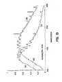
- Figure 19 depicts normalized spectrum A taken for an R.F. powered sulfur lamp without a coating having a substantial spectral component in the ultraviolet region, and normalized spectrum B taken for the same lamp bearing a reflective coating. It is seen that there is proportionately more visible radiation in spectra B.
- the bulb had a 23 mm ID and a 25 mm OD, and was filled with sulfur at a density of .1 mg/cc and 13332, 237 Pa (100 torr) of krypton. It was powered at 220 watts for a power density of 35 watts/cc.
- the coated bulb was coated with alumina at a thickness of about .4 mm, and the alpha was .07.
- unnormalized spectra B appears higher than spectrum A because the detector used is subtended by only a fraction of the radiation emitted from an uncoated bulb, but by a greater fraction of the radiation emitted from an aperture.
- the bulbs may be filled with much lower densities of active material than in the prior art.
- the invention may be utilized with bulbs of different shapes, e.g., spherical, cylindrical, oblate spheroid, toroidal, etc.
- Use of lamps in accordance with the invention include as a projection source and as an illumination source for general lighting.
- bulbs of varying power from lower power e.g., 50 watts
- 300 watts and above including 1000 watt and 3000 watt bulbs may be provided. Since the light may be removed via a light port, loss of light can be low, and the light taken out via a port may be used for distributed type lighting, e.g., in an office building.
- the bulbs and lamps described herein may be used as a recapture engine to convert ultraviolet radiation from an arbitrary source to visible light.
- an external ultraviolet lamp may be provided, and the light therefrom may be fed to a bulb as described herein through a light port. The bulb would then convert the ultraviolet radiation to visible light.
Landscapes
- Physics & Mathematics (AREA)
- Electromagnetism (AREA)
- Engineering & Computer Science (AREA)
- Plasma & Fusion (AREA)
- Vessels And Coating Films For Discharge Lamps (AREA)
- Discharge Lamps And Accessories Thereof (AREA)
- Non-Portable Lighting Devices Or Systems Thereof (AREA)
- Circuit Arrangements For Discharge Lamps (AREA)
- Optical Elements Other Than Lenses (AREA)
- Physical Or Chemical Processes And Apparatus (AREA)
- Exposure Of Semiconductors, Excluding Electron Or Ion Beam Exposure (AREA)
- Discharge Lamp (AREA)
- Spectrometry And Color Measurement (AREA)
- Resistance Heating (AREA)
- Luminescent Compositions (AREA)
Claims (30)
- Procédé de génération de lumière comprenant les étapes consistant à :prévoir une enveloppe (40 ; 19) ;prévoir un matériau de remplissage (42; 13) à l'intérieur de l'enveloppe qui émet de la lumière lorsqu'il est excité, le matériau de remplissage (42 ; 13) étant capable d'absorber de la lumière à une certaine longueur d'onde et de réémettre la lumière absorbée à une longueur d'onde différente, la lumière émise par le matériau de remplissage (42 ; 13) présentant une distribution énergétique spectrale (A) en l'absence de réflexion de lumière de nouveau vers le matériau de remplissage (42 ; 13) ;exciter le matériau de remplissage (42 ; 13) pour obliger le matériau de remplissage (42 ; 13) à émettre de la lumière ; etréfléchir une certaine partie de la lumière émise par le matériau de remplissage (42 ; 13) de nouveau vers le matériau de remplissage (42 ; 13) tout en permettant à une certaine partie de lumière de sortir, caractérisé en ce que la lumière d'excitation est dotée d'une seconde distribution énergétique spectrale (B) avec plus de lumière proportionnellement dans le domaine visible par rapport à la première distribution énergétique spectrale (A), dans lequel la lumière réémise par le matériau de remplissage (42 ; 13) est déplacée en longueur d'onde par rapport à la lumière absorbée et dans lequel l'amplitude du déplacement est fonction d'un chemin optique effectif.
- Procédé selon la revendication 1, dans lequel l'étape consistant à réfléchir la lumière de nouveau vers le matériau de remplissage (42 ; 13) augmente sensiblement le chemin optique effectif par rapport au moins à une partie de la première distribution énergétique spectrale (A).
- Procédé selon la revendication 1, dans lequel l'enveloppe (40 ; 19) est prévue avec une taille d'enveloppe plus petite que celle qui serait requise pour proposer une proportion comparable de lumière dans le domaine visible en l'absence de réflexion de la lumière émise de nouveau à travers le matériau de remplissage (42 ; 13).
- Procédé selon la revendication 1 ou 3, dans lequel le matériau de remplissage (42 ; 13) est prévu avec une densité de matériau de remplissage inférieure à celle qui serait requise pour proposer une proportion comparable de lumière dans le domaine visible en l'absence de réflexion de la lumière émise de nouveau à travers le matériau de remplissage (42 ; 13).
- Procédé selon la revendication 1, dans lequel le matériau de remplissage (42 ; 13) comprend au moins une substance choisie dans le groupe comprenant le soufre et le sélénium, dans lequel une densité du matériau de remplissage est sélectionnée de sorte que la première distribution énergétique spectrale (A) comprend une composante de puissance spectrale substantielle dans le domaine ultraviolet, et dans lequel la seconde distribution énergétique spectrale (B) comprend une composante de puissance spectrale réduite dans le domaine ultraviolet par rapport à la première distribution énergétique spectrale (A).
- Procédé selon la revendication 5, dans lequel la composante de puissance spectrale réduite dans le domaine ultraviolet est au mois 50% inférieure à une grandeur de la composante de puissance spectrale substantielle dans le domaine ultraviolet.
- Procédé selon la revendication 5, dans lequel la seconde distribution énergétique spectrale (B) se trouve principalement dans le domaine visible.
- Procédé selon la revendication 5, dans lequel la densité du matériau de remplissage est suffisamment basse pour permettre un rendement lumineux stable sans faire tourner l'enveloppe (40 ; 19).
- Procédé selon la revendication 1, dans lequel l'étape consistant à réfléchir comprend une étape consistant à proposer un réflecteur (44 ; 10) disposé autour de l'enveloppe (40; 19), ayant une réflectivité d'environ 97% ou plus.
- Lampe à décharge, comprenant :une enveloppe (40 ; 19) ;un matériau de remplissage (42; 13) qui émet de la lumière lorsqu'il est excité, disposé dans l'enveloppe (40 ; 19), le matériau de remplissage (42 ; 13) étant capable d'absorber de la lumière à une certaine longueur d'onde et de réémettre la lumière absorbée à une longueur d'onde différente, la lumière émise par le matériau de remplissage (42 ; 13) présentant une première distribution énergétique spectrale (A) en l'absence de réflexion de lumière de nouveau vers le matériau de remplissage (42 ; 13) ;une source de puissance d'excitation couplée au matériau de remplissage (42 ; 13) pour exciter le matériau de remplissage (42 ; 13) et obliger le matériau de remplissage (42 ; 13) à émettre de la lumière ; etun réflecteur (44 ; 10) disposé autour de l'enveloppe (40 ; 19) et configuré pour réfléchir une certaine partie de la lumière émise par le matériau de remplissage (42; 13) de nouveau vers le matériau de remplissage (42 ; 13) tout en permettant à une certaine partie de lumière de sortir, caractérisée en ce que la lumière d'excitation présente une seconde distribution énergétique spectrale (B) avec plus de lumière proportionnellement dans le domaine visible par rapport à la première distribution énergétique spectrale (A), dans laquelle la lumière réémise par le matériau de remplissage (42 ; 13) est déplacée en longueur d'onde par rapport à la lumière absorbée et dans laquelle l'amplitude du déplacement est fonction d'un chemin optique effectif.
- Lampe selon la revendication 10, dans laquelle le réflecteur (44 ; 10) augmente sensiblement la longueur optique effective par rapport au moins à une partie de la première distribution énergétique spectrale (A).
- Lampe selon la revendication 10, dans laquelle l'enveloppe (40 ; 19) est prévue avec une taille d'enveloppe plus petite que celle qui serait requise pour proposer une proportion comparable de lumière dans le domaine visible en l'absence de réflecteur (44 ; 10).
- Lampe selon la revendication 10 ou 12, dans laquelle le matériau de remplissage (42 ; 13) est prévu avec une densité de matériau de remplissage inférieure à celle qui serait requise pour proposer une proportion comparable de lumière dans le domaine visible en l'absence de réflecteur (44 ; 10).
- Lampe selon la revendication 10, dans laquelle le matériau de remplissage (42 ; 13) comprend au moins une substance choisie dans le groupe comprenant le soufre et le sélénium, dans laquelle une densité de matériau de remplissage est choisie de sorte que la première distribution énergétique spectrale (A) comprend un composant de puissance spectrale substantielle dans le domaine ultraviolet, et dans laquelle la seconde distribution énergétique spectrale (B) comprend une composante de puissance spectrale réduite dans le domaine ultraviolet par rapport à la première distribution énergétique spectrale (A).
- Lampe selon la revendication 14, dans laquelle la composante de puissance spectrale réduite dans le domaine ultraviolet est au moins 50% inférieure à une grandeur de la composante de puissance spectrale substantielle dans le domaine ultraviolet.
- Lampe selon la revendication 14, dans laquelle la seconde distribution énergétique spectrale se trouve principalement dans le domaine visible.
- Lampe selon la revendication 14, dans laquelle la densité du matériau de remplissage est suffisamment basse pour permettre un rendement lumineux stable sans faire tourner l'enveloppe (40 ; 19).
- Lampe selon la revendication 10, dans laquelle le réflecteur (44 ; 10) fournit une réflectivité d'environ 97% ou plus.
- Lampe selon la revendication 10, dans laquelle le réflecteur (44; 10) comprend un matériau doté d'un indice thermique d'expansion similaire par rapport à l'enveloppe (40 ; 19) et qui est peu éloigné de l'enveloppe (40 ; 19).
- Lampe selon la revendication 19, dans laquelle le matériau du réflecteur ne réagit pas avec l'enveloppe (40 ; 19) à la température de fonctionnement de la lampe.
- Lampe selon la revendication 19, dans laquelle le matériau du réflecteur n'adhère pas à l'enveloppe (40 ; 19).
- Lampe selon la revendication 19, dans laquelle le matériau du réflecteur est le même matériau que celui de l'enveloppe (40 ; 19) mais avec une structure différente.
- Lampe selon la revendication 19, dans laquelle le matériau de l'enveloppe est du quartz et dans laquelle le matériau du réflecteur comprend au moins de la silice et de l'alumine.
- Lampe selon la revendication 10, dans laquelle le réflecteur (44) comprend un récipient doté de parois espacées de l'enveloppe (40) et dans laquelle une poudre réfléchissante est disposée dans un espace situé entre les parois du récipient et l'enveloppe (40).
- Lampe selon la revendication 10, dans laquelle le réflecteur (44) comprend une gaine dotée d'une structure rigide.
- Lampe selon la revendication 25, dans laquelle la gaine (44) comprend deux coques (44A, 44B) de céramique intégralement raccordées entre elles.
- Lampe selon la revendication 10, dans laquelle le réflecteur (44 ; 90 ; 91 ; 95) définit un orifice de diffusion (48 ; 92 ; 93 ; 97) à travers lequel la lumière sort de la lampe.
- Lampe selon la revendication 27, dans laquelle l'orifice de diffusion (48 ; 92 ; 93 ; 97) comprend des parois latérales (47) qui sont assez longues pour répartir au hasard la lumière qui sort de l'orifice de diffusion (48 ; 92 ; 93 ; 97).
- Lampe selon la revendication 10, dans laquelle le réflecteur (44 ; 90) définit une ouverture (48 ; 92) à travers laquelle la lumière sort de l'enveloppe (40), et comprenant en outre :un second réflecteur (49 ; 96) disposé de manière adjacente à l'ouverture (48 ; 92) et configuré pour capturer à nouveau la lumière qui pourrait sinon se perdre au niveau d'une interface de l'ouverture (48 ; 92).
- Lampe selon la revendication 10, comprenant en outre :un élément optique (72) éloigné du réflecteur (10) et configuré pour réfléchir les composantes de lumière non désirées qui excitent l'enveloppe (19) de nouveau vers l'enveloppe (19).
Priority Applications (1)
| Application Number | Priority Date | Filing Date | Title |
|---|---|---|---|
| EP01114807A EP1143482A3 (fr) | 1996-05-31 | 1997-05-29 | Lampe à reflexion multiple sans électrode |
Applications Claiming Priority (3)
| Application Number | Priority Date | Filing Date | Title |
|---|---|---|---|
| US65638196A | 1996-05-31 | 1996-05-31 | |
| US656381 | 1996-05-31 | ||
| PCT/US1997/010490 WO1997045858A1 (fr) | 1996-05-31 | 1997-05-29 | Lampe a reflexion multiples sans electrode, au soufre ou au selenium et procede pour obtenir une radiation avec une telle lampe |
Related Child Applications (1)
| Application Number | Title | Priority Date | Filing Date |
|---|---|---|---|
| EP01114807A Division EP1143482A3 (fr) | 1996-05-31 | 1997-05-29 | Lampe à reflexion multiple sans électrode |
Publications (2)
| Publication Number | Publication Date |
|---|---|
| EP0902965A1 EP0902965A1 (fr) | 1999-03-24 |
| EP0902965B1 true EP0902965B1 (fr) | 2003-08-06 |
Family
ID=24632790
Family Applications (2)
| Application Number | Title | Priority Date | Filing Date |
|---|---|---|---|
| EP01114807A Withdrawn EP1143482A3 (fr) | 1996-05-31 | 1997-05-29 | Lampe à reflexion multiple sans électrode |
| EP97928997A Expired - Lifetime EP0902965B1 (fr) | 1996-05-31 | 1997-05-29 | Lampe a reflexions multiples sans electrode, au soufre ou au selenium et procede pour obtenir une radiation avec une telle lampe |
Family Applications Before (1)
| Application Number | Title | Priority Date | Filing Date |
|---|---|---|---|
| EP01114807A Withdrawn EP1143482A3 (fr) | 1996-05-31 | 1997-05-29 | Lampe à reflexion multiple sans électrode |
Country Status (18)
| Country | Link |
|---|---|
| US (3) | US5903091A (fr) |
| EP (2) | EP1143482A3 (fr) |
| JP (1) | JP2000515299A (fr) |
| KR (1) | KR20000016099A (fr) |
| AT (1) | ATE246844T1 (fr) |
| AU (1) | AU720607B2 (fr) |
| BR (1) | BR9709615A (fr) |
| CA (1) | CA2256689A1 (fr) |
| CZ (1) | CZ385298A3 (fr) |
| DE (1) | DE69723978D1 (fr) |
| HU (1) | HUP9904316A3 (fr) |
| NZ (1) | NZ332503A (fr) |
| PL (1) | PL331378A1 (fr) |
| RU (1) | RU2190283C2 (fr) |
| SK (1) | SK157898A3 (fr) |
| TW (1) | TW429391B (fr) |
| WO (1) | WO1997045858A1 (fr) |
| ZA (1) | ZA974773B (fr) |
Families Citing this family (88)
| Publication number | Priority date | Publication date | Assignee | Title |
|---|---|---|---|---|
| US6020676A (en) * | 1992-04-13 | 2000-02-01 | Fusion Lighting, Inc. | Lamp with light reflection back into bulb |
| PL331378A1 (en) * | 1996-05-31 | 1999-07-05 | Fusion Lighting | Multiple-reflection electrode-free sulphur- or selenium-filled lamp and method of generating radiation using such lamp |
| US6291936B1 (en) | 1996-05-31 | 2001-09-18 | Fusion Lighting, Inc. | Discharge lamp with reflective jacket |
| US5949180A (en) * | 1996-12-20 | 1999-09-07 | Fusion Lighting, Inc. | Lamp apparatus with reflective ceramic sleeve holding a plasma that emits light |
| JPH1154091A (ja) * | 1997-07-31 | 1999-02-26 | Matsushita Electron Corp | マイクロ波放電ランプ |
| US6137237A (en) * | 1998-01-13 | 2000-10-24 | Fusion Lighting, Inc. | High frequency inductive lamp and power oscillator |
| US6313587B1 (en) * | 1998-01-13 | 2001-11-06 | Fusion Lighting, Inc. | High frequency inductive lamp and power oscillator |
| CA2317730A1 (fr) * | 1998-01-13 | 1999-07-22 | Donald A. Maclennan | Lampe inductive haute frequence et oscillateur de puissance |
| US6224237B1 (en) * | 1998-04-16 | 2001-05-01 | Honeywell International Inc. | Structure for achieving a linear light source geometry |
| US6172813B1 (en) | 1998-10-23 | 2001-01-09 | Duke University | Projection lens and system including a reflecting linear polarizer |
| US6239917B1 (en) | 1998-10-23 | 2001-05-29 | Duke University | Thermalization using optical components in a lens system |
| US6280035B1 (en) | 1998-10-23 | 2001-08-28 | Duke University | Lens design to eliminate color fringing |
| US6185041B1 (en) | 1998-10-23 | 2001-02-06 | Duke University | Projection lens and system |
| US6220713B1 (en) | 1998-10-23 | 2001-04-24 | Compaq Computer Corporation | Projection lens and system |
| EP1192639A1 (fr) | 1999-05-12 | 2002-04-03 | Fusion Lighting, Inc. | Lampe a micro-ondes de haute luminosite |
| CN1399789A (zh) | 1999-07-02 | 2003-02-26 | 熔化照明股份有限公司 | 高亮度的高输出灯 |
| JP2001076683A (ja) * | 1999-07-02 | 2001-03-23 | Fusion Lighting Inc | トーラス運動を与える誘導性無電極ランプ |
| KR100406143B1 (ko) * | 1999-10-04 | 2003-11-15 | 한국수력원자력 주식회사 | 상관색 온도조절용 무전극 황전등 |
| WO2001027962A2 (fr) * | 1999-10-13 | 2001-04-19 | Fusion Lighting, Inc. | Appareil d'eclairage et procede d'utilisation efficace de la lumiere provenant d'une lampe a fenetre |
| US6922021B2 (en) * | 2000-07-31 | 2005-07-26 | Luxim Corporation | Microwave energized plasma lamp with solid dielectric waveguide |
| US7429818B2 (en) * | 2000-07-31 | 2008-09-30 | Luxim Corporation | Plasma lamp with bulb and lamp chamber |
| US6737809B2 (en) * | 2000-07-31 | 2004-05-18 | Luxim Corporation | Plasma lamp with dielectric waveguide |
| US20020180356A1 (en) * | 2001-04-05 | 2002-12-05 | Kirkpatrick Douglas A. | Sulfur lamp |
| US6620574B2 (en) * | 2001-09-12 | 2003-09-16 | Ppg Industries Ohio, Inc. | Method of treating photoresists using electrodeless UV lamps |
| KR100390516B1 (ko) * | 2001-09-27 | 2003-07-04 | 엘지전자 주식회사 | 마이크로파를 이용한 무전극 방전 램프장치용 일체형 벌브및 그 제조방법 |
| KR20030026806A (ko) * | 2001-09-28 | 2003-04-03 | 주식회사 엘지이아이 | 마이크로파의 누출을 차단하는 장치 및 그 방법 |
| JP2003116970A (ja) * | 2001-10-12 | 2003-04-22 | Matsushita Electric Works Ltd | 殺菌装置および無電極放電バルブ |
| US6559607B1 (en) | 2002-01-14 | 2003-05-06 | Fusion Uv Systems, Inc. | Microwave-powered ultraviolet rotating lamp, and process of use thereof |
| JP4100155B2 (ja) * | 2002-12-05 | 2008-06-11 | オムロン株式会社 | 発光光源、発光光源アレイ及び当該発光光源を用いた機器 |
| US6986591B2 (en) * | 2002-12-20 | 2006-01-17 | Hewlett-Packard Development Company, L.P. | Non-imaging photon concentrator |
| US7400805B2 (en) * | 2003-06-10 | 2008-07-15 | Abu-Ageel Nayef M | Compact light collection system and method |
| US7360936B2 (en) * | 2003-06-10 | 2008-04-22 | Abu-Ageel Nayef M | Method and system of LED light extraction using optical elements |
| KR100531905B1 (ko) * | 2003-08-13 | 2005-11-29 | 엘지전자 주식회사 | 무전극 조명기기의 전구구조 |
| US6971766B2 (en) * | 2003-10-31 | 2005-12-06 | Honeywell International Inc. | Redundant aperture lamp system |
| CN100521861C (zh) * | 2004-03-03 | 2009-07-29 | 友达光电股份有限公司 | 发光装置 |
| US20050286263A1 (en) * | 2004-06-23 | 2005-12-29 | Champion David A | Plasma lamp with light-transmissive waveguide |
| US7300164B2 (en) * | 2004-08-26 | 2007-11-27 | Hewlett-Packard Development Company, L.P. | Morphing light guide |
| WO2006035339A1 (fr) * | 2004-09-28 | 2006-04-06 | Philips Intellectual Property & Standards Gmbh | Lampe a decharge de gaz basse pression |
| DE102004047375A1 (de) * | 2004-09-29 | 2006-04-06 | Patent-Treuhand-Gesellschaft für elektrische Glühlampen mbH | Dielektrische behinderte Entladungslampe mit Manschette |
| DE102004047374A1 (de) * | 2004-09-29 | 2006-04-06 | Patent-Treuhand-Gesellschaft für elektrische Glühlampen mbH | Dielektrisch behinderte Entladungslampe mit elektrischer Abschirmung |
| DE102004047376A1 (de) * | 2004-09-29 | 2006-04-06 | Patent-Treuhand-Gesellschaft für elektrische Glühlampen mbH | Dielektrisch behinderte Entladungslampe mit steckbaren Elektroden |
| DE102004047373A1 (de) * | 2004-09-29 | 2006-04-06 | Patent-Treuhand-Gesellschaft für elektrische Glühlampen mbH | Beleuchtungssystem mit dielektrisch behinderter Entladungslampe und zugehörigem Vorschaltgerät |
| US7303307B2 (en) * | 2004-10-06 | 2007-12-04 | Osram Sylvania Inc. | Electrodeless lamp with incorporated reflector |
| US7994721B2 (en) * | 2005-10-27 | 2011-08-09 | Luxim Corporation | Plasma lamp and methods using a waveguide body and protruding bulb |
| US7638951B2 (en) | 2005-10-27 | 2009-12-29 | Luxim Corporation | Plasma lamp with stable feedback amplification and method therefor |
| US8022607B2 (en) * | 2005-10-27 | 2011-09-20 | Luxim Corporation | Plasma lamp with small power coupling surface |
| US7791278B2 (en) | 2005-10-27 | 2010-09-07 | Luxim Corporation | High brightness plasma lamp |
| US7906910B2 (en) * | 2005-10-27 | 2011-03-15 | Luxim Corporation | Plasma lamp with conductive material positioned relative to RF feed |
| US7791280B2 (en) | 2005-10-27 | 2010-09-07 | Luxim Corporation | Plasma lamp using a shaped waveguide body |
| US7855511B2 (en) * | 2005-10-27 | 2010-12-21 | Luxim Corporation | Plasma lamp with phase control |
| US7701143B2 (en) * | 2005-10-27 | 2010-04-20 | Luxim Corporation | Plasma lamp with compact waveguide |
| EP1977156A4 (fr) * | 2006-01-04 | 2011-06-22 | Luxim Corp | Lampe a arc de plasma a antenne de concentration de champ |
| US20070280622A1 (en) * | 2006-06-02 | 2007-12-06 | 3M Innovative Properties Company | Fluorescent light source having light recycling means |
| US20070279914A1 (en) * | 2006-06-02 | 2007-12-06 | 3M Innovative Properties Company | Fluorescent volume light source with reflector |
| JP4857939B2 (ja) * | 2006-06-19 | 2012-01-18 | ウシオ電機株式会社 | 放電ランプ |
| US20080030974A1 (en) * | 2006-08-02 | 2008-02-07 | Abu-Ageel Nayef M | LED-Based Illumination System |
| WO2008042703A1 (fr) * | 2006-09-29 | 2008-04-10 | 3M Innovative Properties Company | Source lumineuse à volume fluorescent comprenant de multiples espèces fluorescentes |
| WO2008048972A2 (fr) * | 2006-10-16 | 2008-04-24 | Luxim Corporation | Configurations de source rf et assemblage pour lampe à plasma |
| WO2008048968A2 (fr) * | 2006-10-16 | 2008-04-24 | Luxim Corporation | Lampe à plasma et charge sans électrode |
| EP2087399A4 (fr) * | 2006-10-16 | 2010-05-05 | Luxim Corp | Systèmes à source de lumière modulée, et procédés |
| US8981663B2 (en) * | 2006-10-16 | 2015-03-17 | Luxim Corporation | Discharge lamp using spread spectrum |
| US20100253231A1 (en) * | 2006-10-16 | 2010-10-07 | Devincentis Marc | Electrodeless plasma lamp systems and methods |
| WO2008051877A2 (fr) * | 2006-10-20 | 2008-05-02 | Luxim Corporation | Lampes sans électrode avec angle de vue élevé de l'arc de plasma |
| US8143801B2 (en) * | 2006-10-20 | 2012-03-27 | Luxim Corporation | Electrodeless lamps and methods |
| US20080211971A1 (en) * | 2007-01-08 | 2008-09-04 | Luxim Corporation | Color balancing systems and methods |
| US8159136B2 (en) * | 2007-02-07 | 2012-04-17 | Luxim Corporation | Frequency tunable resonant cavity for use with an electrodeless plasma lamp |
| US8063565B2 (en) * | 2007-07-23 | 2011-11-22 | Luxim Corporation | Method and apparatus to reduce arcing in electrodeless lamps |
| US8084955B2 (en) * | 2007-07-23 | 2011-12-27 | Luxim Corporation | Systems and methods for improved startup and control of electrodeless plasma lamp using current feedback |
| US20090050905A1 (en) * | 2007-08-20 | 2009-02-26 | Abu-Ageel Nayef M | Highly Efficient Light-Emitting Diode |
| US20090167201A1 (en) * | 2007-11-07 | 2009-07-02 | Luxim Corporation. | Light source and methods for microscopy and endoscopy |
| US9151884B2 (en) * | 2008-02-01 | 2015-10-06 | 3M Innovative Properties Company | Fluorescent volume light source with active chromphore |
| DE102008028233A1 (de) * | 2008-06-16 | 2009-12-17 | Heraeus Noblelight Gmbh | Kompaktes UV-Bestrahlungsmodul |
| US8456091B2 (en) * | 2008-09-09 | 2013-06-04 | Kino Flo, Inc. | Method and apparatus for maintaining constant color temperature of a fluorescent lamp |
| US20100156310A1 (en) * | 2008-09-18 | 2010-06-24 | Luxim Corporation | Low frequency electrodeless plasma lamp |
| US8319439B2 (en) * | 2008-09-18 | 2012-11-27 | Luxim Corporation | Electrodeless plasma lamp and drive circuit |
| US8304994B2 (en) * | 2008-10-09 | 2012-11-06 | Luxim Corporation | Light collection system for an electrodeless RF plasma lamp |
| US20100123396A1 (en) * | 2008-10-09 | 2010-05-20 | Luxim Corporation | Replaceable lamp bodies for electrodeless plasma lamps |
| US20100102724A1 (en) * | 2008-10-21 | 2010-04-29 | Luxim Corporation | Method of constructing ceramic body electrodeless lamps |
| TWI386970B (zh) * | 2008-11-18 | 2013-02-21 | Ind Tech Res Inst | 應用氣態硫化物之發光裝置 |
| TWI379339B (en) * | 2008-11-18 | 2012-12-11 | Ind Tech Res Inst | Light-emitting device of excited sulfur medium by inductively-coupled electrons |
| US20100165306A1 (en) * | 2008-12-31 | 2010-07-01 | Luxmi Corporation | Beam projection systems and methods |
| RU2551644C2 (ru) * | 2009-01-06 | 2015-05-27 | Лаксим Корпорейшн | Безэлектродная плазменная лампа (варианты) |
| US8854734B2 (en) * | 2009-11-12 | 2014-10-07 | Vela Technologies, Inc. | Integrating optical system and methods |
| US8853931B2 (en) * | 2009-12-18 | 2014-10-07 | Luxim Corporation | Electrodeless plasma lamp with modified power coupling |
| RU2416839C1 (ru) * | 2009-12-28 | 2011-04-20 | Негосударственное научно-образовательное учреждение "Саранский Дом науки и техники Российского союза научных и инженерных общественных организаций" | Безэлектродная высокочастотная лампа высокого давления |
| US8426800B2 (en) | 2010-09-09 | 2013-04-23 | Vela Technologies, Inc. | Integrating optical systems and methods |
| EP2622943A4 (fr) | 2010-09-30 | 2014-10-29 | Luxim Corp | Lampe à plasma dotée de composants localisés |
| TWI580887B (zh) * | 2015-02-06 | 2017-05-01 | 飛立威光能股份有限公司 | 一種照明系統及其製造方法 |
Family Cites Families (50)
| Publication number | Priority date | Publication date | Assignee | Title |
|---|---|---|---|---|
| US2135480A (en) * | 1936-08-26 | 1938-11-08 | Birdseye Electric Company | Reflecting glow lamp |
| US3042795A (en) * | 1958-10-01 | 1962-07-03 | Nord Photocopy And Electronics | Photocopy machine |
| US3763392A (en) * | 1972-01-17 | 1973-10-02 | Charybdis Inc | High pressure method for producing an electrodeless plasma arc as a light source |
| US3931536A (en) * | 1974-07-15 | 1976-01-06 | Gte Sylvania Incorporated | Efficiency arc discharge lamp |
| JPS52146071A (en) * | 1976-05-31 | 1977-12-05 | Hitachi Ltd | Non-polarized discharge tube |
| JPS5340688A (en) * | 1976-09-27 | 1978-04-13 | Fuji Oil Co Ltd | Method of manufacturing solidified matter |
| US4071798A (en) * | 1977-04-01 | 1978-01-31 | Xerox Corporation | Sodium vapor lamp with emission aperture |
| JPS57148764A (en) * | 1981-03-12 | 1982-09-14 | Toppan Printing Co Ltd | Color copying machine for detection of plate |
| US4792716A (en) * | 1981-10-29 | 1988-12-20 | Duro-Test Corporation | Energy-efficient electric discharge lamp with reflective coating |
| US4532427A (en) * | 1982-03-29 | 1985-07-30 | Fusion Systems Corp. | Method and apparatus for performing deep UV photolithography |
| EP0099607B1 (fr) * | 1982-07-23 | 1986-04-23 | Koninklijke Philips Electronics N.V. | Lampe électrique à réflecteur |
| US4501993A (en) * | 1982-10-06 | 1985-02-26 | Fusion Systems Corporation | Deep UV lamp bulb |
| JPS60117539A (ja) * | 1983-11-29 | 1985-06-25 | Matsushita Electric Works Ltd | 無電極放電ランプ |
| DE3525482C1 (de) * | 1985-07-17 | 1987-02-05 | Klimsch & Co | Belichtungsvorrichtung |
| EP0219915B1 (fr) * | 1985-10-21 | 1990-02-07 | Koninklijke Philips Electronics N.V. | Dispositif d'irradiation |
| US4691924A (en) * | 1986-05-07 | 1987-09-08 | J. B. Golf Enterprises, Inc. | Golfer's arm movement control device |
| JP2834118B2 (ja) * | 1986-12-01 | 1998-12-09 | 株式会社日立製作所 | 半導体集積回路 |
| US4735495A (en) * | 1986-12-12 | 1988-04-05 | General Electric Co. | Light source for liquid crystal display panels utilizing internally reflecting light pipes and integrating sphere |
| JPH0697605B2 (ja) * | 1987-05-25 | 1994-11-30 | 松下電工株式会社 | 無電極放電灯装置 |
| JPH0697604B2 (ja) * | 1987-05-25 | 1994-11-30 | 松下電工株式会社 | 無電極放電灯装置 |
| JP2577408B2 (ja) * | 1987-11-28 | 1997-01-29 | 株式会社東芝 | フロッピーディスク装置のレシーバ機構 |
| US4839553A (en) * | 1987-12-21 | 1989-06-13 | Gte Products Corporation | Reflector lamp having complementary dichroic filters on the reflector and lens for emitting colored light |
| US4877991A (en) * | 1987-12-21 | 1989-10-31 | Colterjohn Jr Walter L | Optical radiation source |
| US4872741A (en) * | 1988-07-22 | 1989-10-10 | General Electric Company | Electrodeless panel discharge lamp liquid crystal display |
| US4950059A (en) * | 1988-10-11 | 1990-08-21 | General Electric Company | Combination lamp and integrating sphere for efficiently coupling radiant energy from a gas discharge to a lightguide |
| USRE34492E (en) * | 1988-10-11 | 1993-12-28 | General Electric Company | Combination lamp and integrating sphere for efficiently coupling radiant energy from a gas discharge to a lightguide |
| US4978891A (en) * | 1989-04-17 | 1990-12-18 | Fusion Systems Corporation | Electrodeless lamp system with controllable spectral output |
| EP0457645B1 (fr) * | 1990-05-15 | 1994-07-13 | Francis David | Dispositif d'éclairage |
| US5113121A (en) * | 1990-05-15 | 1992-05-12 | Gte Laboratories Incorporated | Electrodeless HID lamp with lamp capsule |
| US5404076A (en) * | 1990-10-25 | 1995-04-04 | Fusion Systems Corporation | Lamp including sulfur |
| EP0636275B1 (fr) * | 1990-10-25 | 2007-01-03 | Fusion Lighting, Inc. | Lampe a caracteristiques spectrales regulables |
| DE69125499T2 (de) * | 1990-10-25 | 1997-07-17 | Fusion Systems Corp., Rockville, Md. | Hochleistungslampe |
| US5798611A (en) | 1990-10-25 | 1998-08-25 | Fusion Lighting, Inc. | Lamp having controllable spectrum |
| US5177396A (en) * | 1990-12-19 | 1993-01-05 | Gte Products Corporation | Mirror with dichroic coating lamp housing |
| US5117312A (en) * | 1991-01-04 | 1992-05-26 | Fusion Systems Corporation | Apparatus including concave reflectors and a line of optical fibers |
| SU1765858A1 (ru) * | 1991-01-09 | 1992-09-30 | Ереванский Электроламповый Завод | Газоразр дна лампа |
| US5168193A (en) * | 1991-09-30 | 1992-12-01 | General Electric Company | Lamp having boron nitride reflective coating |
| TW249860B (fr) * | 1991-11-04 | 1995-06-21 | Gen Electric | |
| US5504391A (en) * | 1992-01-29 | 1996-04-02 | Fusion Systems Corporation | Excimer lamp with high pressure fill |
| US5192629A (en) * | 1992-04-21 | 1993-03-09 | Bell Communications Research, Inc. | High-voltage-stable electrolytes for Li1+x Mn2 O4 /carbon secondary batteries |
| DE69329032T2 (de) * | 1992-09-30 | 2001-03-22 | Fusion Lighting Inc., Rockville | Elektrodenlose lampe mit drehender birne |
| US5541475A (en) * | 1993-04-16 | 1996-07-30 | Fusion Lighting, Inc. | Electrodeless lamp with profiled wall thickness |
| DE4318905A1 (de) * | 1993-06-07 | 1994-12-08 | Patent Treuhand Ges Fuer Elektrische Gluehlampen Mbh | Metallhalogenidentladungslampe und Verfahren zu ihrer Herstellung |
| BE1007440A3 (nl) * | 1993-08-20 | 1995-06-13 | Philips Electronics Nv | Lagedrukkwikdampontladingslamp. |
| NZ278181A (en) * | 1993-10-15 | 1999-02-25 | Fusion Lighting Inc | Electrodeless lamp containing sulphur, selenium or tellurium, energised by microwaves |
| GB2284704B (en) * | 1993-12-10 | 1998-07-08 | Gen Electric | Patterned optical interference coatings for electric lamps |
| US5914564A (en) * | 1994-04-07 | 1999-06-22 | The Regents Of The University Of California | RF driven sulfur lamp having driving electrodes which face each other |
| US5610469A (en) * | 1995-03-16 | 1997-03-11 | General Electric Company | Electric lamp with ellipsoidal shroud |
| US5990624A (en) | 1995-09-25 | 1999-11-23 | Matsushita Electric Works R&D Laboratory, Inc. | Color sulfur lamp including means for intercepting and re-mitting light of a desired spectral distribution |
| PL331378A1 (en) * | 1996-05-31 | 1999-07-05 | Fusion Lighting | Multiple-reflection electrode-free sulphur- or selenium-filled lamp and method of generating radiation using such lamp |
-
1997
- 1997-05-29 PL PL97331378A patent/PL331378A1/xx unknown
- 1997-05-29 TW TW086107291A patent/TW429391B/zh active
- 1997-05-29 KR KR1019980709666A patent/KR20000016099A/ko not_active Ceased
- 1997-05-29 NZ NZ332503A patent/NZ332503A/xx unknown
- 1997-05-29 DE DE69723978T patent/DE69723978D1/de not_active Expired - Lifetime
- 1997-05-29 AT AT97928997T patent/ATE246844T1/de not_active IP Right Cessation
- 1997-05-29 CZ CZ983852A patent/CZ385298A3/cs unknown
- 1997-05-29 AU AU33130/97A patent/AU720607B2/en not_active Ceased
- 1997-05-29 EP EP01114807A patent/EP1143482A3/fr not_active Withdrawn
- 1997-05-29 RU RU98123815/09A patent/RU2190283C2/ru active
- 1997-05-29 US US08/865,516 patent/US5903091A/en not_active Expired - Fee Related
- 1997-05-29 SK SK1578-98A patent/SK157898A3/sk unknown
- 1997-05-29 WO PCT/US1997/010490 patent/WO1997045858A1/fr not_active Ceased
- 1997-05-29 JP JP09543101A patent/JP2000515299A/ja active Pending
- 1997-05-29 HU HU9904316A patent/HUP9904316A3/hu unknown
- 1997-05-29 EP EP97928997A patent/EP0902965B1/fr not_active Expired - Lifetime
- 1997-05-29 BR BR9709615A patent/BR9709615A/pt unknown
- 1997-05-29 CA CA002256689A patent/CA2256689A1/fr not_active Abandoned
- 1997-05-30 ZA ZA9704773A patent/ZA974773B/xx unknown
-
1999
- 1999-05-11 US US09/309,272 patent/US6246160B1/en not_active Expired - Fee Related
-
2001
- 2001-06-06 US US09/874,374 patent/US6509675B2/en not_active Expired - Fee Related
Also Published As
| Publication number | Publication date |
|---|---|
| DE69723978D1 (de) | 2003-09-11 |
| US6509675B2 (en) | 2003-01-21 |
| ZA974773B (en) | 1997-12-01 |
| JP2000515299A (ja) | 2000-11-14 |
| EP0902965A1 (fr) | 1999-03-24 |
| AU720607B2 (en) | 2000-06-08 |
| NZ332503A (en) | 2000-03-27 |
| KR20000016099A (ko) | 2000-03-25 |
| HUP9904316A2 (hu) | 2000-04-28 |
| EP1143482A2 (fr) | 2001-10-10 |
| AU3313097A (en) | 1998-01-05 |
| US20020017845A1 (en) | 2002-02-14 |
| WO1997045858A1 (fr) | 1997-12-04 |
| SK157898A3 (en) | 1999-07-12 |
| ATE246844T1 (de) | 2003-08-15 |
| US5903091A (en) | 1999-05-11 |
| TW429391B (en) | 2001-04-11 |
| CA2256689A1 (fr) | 1997-12-04 |
| HUP9904316A3 (en) | 2000-05-29 |
| EP1143482A3 (fr) | 2001-12-12 |
| CZ385298A3 (cs) | 1999-05-12 |
| RU2190283C2 (ru) | 2002-09-27 |
| PL331378A1 (en) | 1999-07-05 |
| BR9709615A (pt) | 1999-08-10 |
| US6246160B1 (en) | 2001-06-12 |
Similar Documents
| Publication | Publication Date | Title |
|---|---|---|
| EP0902965B1 (fr) | Lampe a reflexions multiples sans electrode, au soufre ou au selenium et procede pour obtenir une radiation avec une telle lampe | |
| US6291936B1 (en) | Discharge lamp with reflective jacket | |
| CA1197549A (fr) | Source de lumiere produite par un plasma engendre par micro-ondes | |
| US4507587A (en) | Microwave generated electrodeless lamp for producing bright output | |
| KR101589646B1 (ko) | 마이크로파 동력식 광원 | |
| KR101038450B1 (ko) | 조명 장치 및 투사 시스템 | |
| US20080203922A1 (en) | High intensity plasma lamp | |
| US20020030453A1 (en) | High brightness microwave lamp | |
| US20110181184A1 (en) | Plasma lamp with field-concentrating antenna | |
| CN1088253C (zh) | 无电极荧光反射灯 | |
| EP1070339B1 (fr) | Source lumineuse de plasma activee par microondes | |
| JP2001266803A (ja) | 無電極放電ランプ | |
| US20100270920A1 (en) | Lucent plasma crucible | |
| US8847488B2 (en) | Fill combination and method for high intensity lamps | |
| CZ286454B6 (en) | Lamp | |
| IL126730A (en) | Multiple reflection electrodeless lamp with sulfur or selenium fill and method for providing radiation using such a lamp | |
| MacLennan et al. | Discharge lamp with reflective jacket | |
| MXPA98009961A (es) | Lampara sin electrodo de reflexion multiple con relleno de azufre o selenio y metodo para proporcionar radiacion usando esa lampara | |
| CN1222248A (zh) | 具有硫或硒填充物的多次反射无电极灯和用它辐射的方法 | |
| KR20010035890A (ko) | 무전극 방전등용 공동-반사경 일체형 전구 | |
| JPS62163383A (ja) | レ−ザ発振装置 |
Legal Events
| Date | Code | Title | Description |
|---|---|---|---|
| PUAI | Public reference made under article 153(3) epc to a published international application that has entered the european phase |
Free format text: ORIGINAL CODE: 0009012 |
|
| 17P | Request for examination filed |
Effective date: 19981230 |
|
| AK | Designated contracting states |
Kind code of ref document: A1 Designated state(s): AT BE CH DE DK ES FI FR GB GR IE IT LI NL PT SE |
|
| 17Q | First examination report despatched |
Effective date: 20001213 |
|
| GRAH | Despatch of communication of intention to grant a patent |
Free format text: ORIGINAL CODE: EPIDOS IGRA |
|
| RIC1 | Information provided on ipc code assigned before grant |
Free format text: 7H 01J 61/02 A, 7H 01J 61/12 B, 7H 01J 61/18 B, 7H 01J 61/35 B, 7H 01J 61/42 B, 7H 01J 61/38 B, 7H 01J 17/16 B, 7H 01J 17/20 B, 7H 05B 41/24 B, 7H 01J 65/04 B |
|
| RTI1 | Title (correction) |
Free format text: MULTIPLE REFLECTION ELECTRODELESS LAMP WITH SULFUR OR SELENIUM FILL AND METHOD FOR PROVIDING RADIATION USING SUCH A LAMP |
|
| GRAH | Despatch of communication of intention to grant a patent |
Free format text: ORIGINAL CODE: EPIDOS IGRA |
|
| GRAA | (expected) grant |
Free format text: ORIGINAL CODE: 0009210 |
|
| AK | Designated contracting states |
Designated state(s): AT BE CH DE DK ES FI FR GB GR IE IT LI NL PT SE |
|
| PG25 | Lapsed in a contracting state [announced via postgrant information from national office to epo] |
Ref country code: NL Free format text: LAPSE BECAUSE OF FAILURE TO SUBMIT A TRANSLATION OF THE DESCRIPTION OR TO PAY THE FEE WITHIN THE PRESCRIBED TIME-LIMIT Effective date: 20030806 Ref country code: LI Free format text: LAPSE BECAUSE OF FAILURE TO SUBMIT A TRANSLATION OF THE DESCRIPTION OR TO PAY THE FEE WITHIN THE PRESCRIBED TIME-LIMIT Effective date: 20030806 Ref country code: IT Free format text: LAPSE BECAUSE OF FAILURE TO SUBMIT A TRANSLATION OF THE DESCRIPTION OR TO PAY THE FEE WITHIN THE PRE;WARNING: LAPSES OF ITALIAN PATENTS WITH EFFECTIVE DATE BEFORE 2007 MAY HAVE OCCURRED AT ANY TIME BEFORE 2007. THE CORRECT EFFECTIVE DATE MAY BE DIFFERENT FROM THE ONE RECORDED.SCRIBED TIME-LIMIT Effective date: 20030806 Ref country code: FR Free format text: LAPSE BECAUSE OF FAILURE TO SUBMIT A TRANSLATION OF THE DESCRIPTION OR TO PAY THE FEE WITHIN THE PRESCRIBED TIME-LIMIT Effective date: 20030806 Ref country code: FI Free format text: LAPSE BECAUSE OF FAILURE TO SUBMIT A TRANSLATION OF THE DESCRIPTION OR TO PAY THE FEE WITHIN THE PRESCRIBED TIME-LIMIT Effective date: 20030806 Ref country code: CH Free format text: LAPSE BECAUSE OF FAILURE TO SUBMIT A TRANSLATION OF THE DESCRIPTION OR TO PAY THE FEE WITHIN THE PRESCRIBED TIME-LIMIT Effective date: 20030806 Ref country code: BE Free format text: LAPSE BECAUSE OF FAILURE TO SUBMIT A TRANSLATION OF THE DESCRIPTION OR TO PAY THE FEE WITHIN THE PRESCRIBED TIME-LIMIT Effective date: 20030806 Ref country code: AT Free format text: LAPSE BECAUSE OF FAILURE TO SUBMIT A TRANSLATION OF THE DESCRIPTION OR TO PAY THE FEE WITHIN THE PRESCRIBED TIME-LIMIT Effective date: 20030806 |
|
| REG | Reference to a national code |
Ref country code: GB Ref legal event code: FG4D |
|
| REG | Reference to a national code |
Ref country code: CH Ref legal event code: EP |
|
| REG | Reference to a national code |
Ref country code: IE Ref legal event code: FG4D |
|
| REF | Corresponds to: |
Ref document number: 69723978 Country of ref document: DE Date of ref document: 20030911 Kind code of ref document: P |
|
| PG25 | Lapsed in a contracting state [announced via postgrant information from national office to epo] |
Ref country code: SE Free format text: LAPSE BECAUSE OF FAILURE TO SUBMIT A TRANSLATION OF THE DESCRIPTION OR TO PAY THE FEE WITHIN THE PRESCRIBED TIME-LIMIT Effective date: 20031106 Ref country code: GR Free format text: LAPSE BECAUSE OF FAILURE TO SUBMIT A TRANSLATION OF THE DESCRIPTION OR TO PAY THE FEE WITHIN THE PRESCRIBED TIME-LIMIT Effective date: 20031106 Ref country code: DK Free format text: LAPSE BECAUSE OF FAILURE TO SUBMIT A TRANSLATION OF THE DESCRIPTION OR TO PAY THE FEE WITHIN THE PRESCRIBED TIME-LIMIT Effective date: 20031106 |
|
| PG25 | Lapsed in a contracting state [announced via postgrant information from national office to epo] |
Ref country code: DE Free format text: LAPSE BECAUSE OF FAILURE TO SUBMIT A TRANSLATION OF THE DESCRIPTION OR TO PAY THE FEE WITHIN THE PRESCRIBED TIME-LIMIT Effective date: 20031107 |
|
| PG25 | Lapsed in a contracting state [announced via postgrant information from national office to epo] |
Ref country code: ES Free format text: LAPSE BECAUSE OF FAILURE TO SUBMIT A TRANSLATION OF THE DESCRIPTION OR TO PAY THE FEE WITHIN THE PRESCRIBED TIME-LIMIT Effective date: 20031117 |
|
| NLV1 | Nl: lapsed or annulled due to failure to fulfill the requirements of art. 29p and 29m of the patents act | ||
| PG25 | Lapsed in a contracting state [announced via postgrant information from national office to epo] |
Ref country code: PT Free format text: LAPSE BECAUSE OF FAILURE TO SUBMIT A TRANSLATION OF THE DESCRIPTION OR TO PAY THE FEE WITHIN THE PRESCRIBED TIME-LIMIT Effective date: 20040106 |
|
| REG | Reference to a national code |
Ref country code: CH Ref legal event code: PL |
|
| PG25 | Lapsed in a contracting state [announced via postgrant information from national office to epo] |
Ref country code: GB Free format text: LAPSE BECAUSE OF NON-PAYMENT OF DUE FEES Effective date: 20040529 |
|
| PG25 | Lapsed in a contracting state [announced via postgrant information from national office to epo] |
Ref country code: IE Free format text: LAPSE BECAUSE OF NON-PAYMENT OF DUE FEES Effective date: 20040531 |
|
| PLBE | No opposition filed within time limit |
Free format text: ORIGINAL CODE: 0009261 |
|
| STAA | Information on the status of an ep patent application or granted ep patent |
Free format text: STATUS: NO OPPOSITION FILED WITHIN TIME LIMIT |
|
| 26N | No opposition filed |
Effective date: 20040507 |
|
| EN | Fr: translation not filed | ||
| GBPC | Gb: european patent ceased through non-payment of renewal fee | ||
| REG | Reference to a national code |
Ref country code: IE Ref legal event code: MM4A |