EP0902948B1 - Datenträgerverpackung - Google Patents
Datenträgerverpackung Download PDFInfo
- Publication number
- EP0902948B1 EP0902948B1 EP97917983A EP97917983A EP0902948B1 EP 0902948 B1 EP0902948 B1 EP 0902948B1 EP 97917983 A EP97917983 A EP 97917983A EP 97917983 A EP97917983 A EP 97917983A EP 0902948 B1 EP0902948 B1 EP 0902948B1
- Authority
- EP
- European Patent Office
- Prior art keywords
- data medium
- holding
- packaging
- data
- data carrier
- Prior art date
- Legal status (The legal status is an assumption and is not a legal conclusion. Google has not performed a legal analysis and makes no representation as to the accuracy of the status listed.)
- Expired - Lifetime
Links
Images


Classifications
-
- G—PHYSICS
- G11—INFORMATION STORAGE
- G11B—INFORMATION STORAGE BASED ON RELATIVE MOVEMENT BETWEEN RECORD CARRIER AND TRANSDUCER
- G11B33/00—Constructional parts, details or accessories not provided for in the other groups of this subclass
- G11B33/02—Cabinets; Cases; Stands; Disposition of apparatus therein or thereon
- G11B33/04—Cabinets; Cases; Stands; Disposition of apparatus therein or thereon modified to store record carriers
- G11B33/0405—Cabinets; Cases; Stands; Disposition of apparatus therein or thereon modified to store record carriers for storing discs
- G11B33/0433—Multiple disc containers
- G11B33/0444—Multiple disc containers for discs without cartridge
- G11B33/045—Multiple disc containers for discs without cartridge comprising centre hole locking means
Definitions
- the invention relates to packaging for holding thin, essentially round, at most damage-taking disks, which one - in their Dimensions standardized - central opening for insertion the spindle of a device that is used for retrieval or reading the stored data is suitable.
- Disk such as compact disks (CD), video disks (VD) or mini disks (MD) have precisely this shape, which is why the inventive Packaging for storage, display, sale and transporting such data carriers is particularly suitable.
- the invention relates to a method and a device for producing this packaging.
- CD packaging made of transparent plastic material in various embodiments is known. That packaging consists of one or more boxes for one or two CDs each. The boxes are connected to one another via hinges or with lids, so that each desired CD can be removed individually from the opened packaging. Inserts printed in one or more colors (so-called "inlay cards”), preferably made of paper, inform the interested buyer or user of the CD, for example, about the content or the possibilities thereof. The amount of information is often so large that a small booklet or booklet is placed in the packaging of the CD. Such CD packaging thus contains both plastic and paper.
- GB 2 272 685 ( D7 ) describes pocket-shaped containers which are folded from a piece of paper and have bellows-like side parts. Data carriers are inserted into these pockets from the side in an unusual way, so that loading with CDs that has already become standard has to be avoided. These bags can optionally be pushed into another container made of the same material, which ensures improved stability of the packaging. Nevertheless, the areas of the CD from which data can be called up are at least partially directly on the packaging, so that there are fears of grinding marks on the CD surface.
- the data-carrying surface of a CD is here at least partially brought into contact with the packaging, which in turn, together with the low stability, can be regarded as a disadvantage.
- This second group (D7 to D10) of data carrier packaging has significant disadvantages, above all due to the necessary alternative types of loading with CDs and the low stability.
- the goal of using monomaterial in US Pat. No. 5,427,236 ( D13 ) has also been insufficiently achieved because, despite largely avoiding plastic material, the central receiver for the CD still contains such material.
- the stability of the packaging also leaves something to be desired here.
- the object of the present invention is to provide a packaging for disk-shaped data carriers, in particular CDs, VDs or MDs, which combines the demand for the use of a uniform packaging material made of ecologically harmless and renewable raw material, economy, unbreakability, stability, printability and low weight the possibility of using CDs as standard, ie preferably automatically, and storing them in such a way that they only come into contact with the packaging in areas that do not contain any information that can be called up.
- Another data carrier packaging is known from EP 0 698 883.
- This document is considered to be the closest prior art and discloses a data carrier packaging which has a folding cardboard packaging and a holder which is largely manufactured from a biodegradable material (with at least 25% by weight, preferably 80% by weight starch) by injection molding.
- a biodegradable material with at least 25% by weight, preferably 80% by weight starch
- the direct replacement of which it is intended to serve this injection-molded element made of natural polymers is mixed with additives, such as vegetable fibers .
- This packaging does not live up to the task because the demand for a uniform packaging material is not fulfilled: the high proportion of starch does not prevent biodegradation, but it at least makes it difficult to reuse the packaging material.
- a cardboard packaging is known from WO 95/27286. She points a receiving part (with or without a lid) and a cover in which the receiving part - to prevent opening the cover or the data carrier falls out) is inserted.
- Another disk packaging from monomaterial is known from US 5,186,327. This exists from a recording part in which the data carrier is inserted and from a shell in which the receiving part is inserted (see there Figures 3 and 4). To take out of the data medium, the recording part must first again be pulled out of the envelope. These two packages do not do the job because through them the demand for standard loading a disk is not met.
- the task is accomplished by the method fulfilled according to claim 1.
- Preferred further training this inventive method result from the dependent claims 2 to 10.
- Preferred developments of this invention Packaging result from the dependent claims 12 to 23.
- the basic material of such Papers or boxes consist of natural fibers, which as Primary fibers in the form of cellulose from various Tree species or as secondary fibers by recycling waste paper and carton can be obtained.
- This according to the invention Packaging is, according to further aspects of the invention, produced by a method or an apparatus which processing by means of creasing, folding and gluing or the deep deformation of parts of the packaging. The Manufacturing is carried out simply, quickly and automatically and is therefore also economical.
- This packaging out A mono material is characterized by one - the one used Corresponding material paper or cardboard - unbreakability and printability.
- CDs can - Using an embodiment of the invention Packaging - using standard methods, e.g. automated used or loaded and stored so that the CDs only in areas that are not accessible Information touches the packaging come. These disks are from the bottom and the Cover inner surface spaced and are only in the central or peripheral part which does not have any retrievable data on a step-like surface.
- the mounting pin fixes the CD so that the data carrier is immobile in all directions of the packaging is held.
- the present data carrier packaging according to the invention compared to known CD packaging made of mixed material (first group) can biodegradability or biodegradability or compostability, use as renewable Energy source or recycling as a supplier of secondary or recycled fibers.
- first group biodegradability or biodegradability or compostability
- second group monomaterial
- D1 and D2 probably most widespread packaging
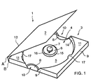
- the data carrier packaging 1 in FIG. 1 comprises a lid 2 and a recording part 3 for a disk that has something is raised, it is folded around the axes A or B.
- the receiving element 4 with a substantially round Well 5 and a concentric to it Survey is evident.
- a cylindrical locating pin 7 is preferably also concentric on the elevation surface 6 arranged.
- the outer diameter of the survey area 6 or the receiving pin 7 are somewhat smaller than the diameter of the central, non-data bearing area of a data carrier to be used or the central, standardized opening of a data carrier to be used, which is known to accommodate a drive spindle Data reader is used.
- recessed grips 8 are visible to facilitate them removing a disk.
- the side walls 9 of the data carrier packaging cut out In the area of the recessed grips 8 are the side walls 9 of the data carrier packaging cut out. Deviating from the illustration in FIG. 1 can in a further embodiment on the recessed grips 8 or at least partially omitted the cutouts 10 become.
- Cover surfaces 11 of the envelope element 12 cover the outer, high parts of the receiving element 4.
- the high parts of the receiving element 4 are vertical, preferably circular and slightly conical Inner walls 14 connected to the bottom of the recess 5 or molded in one piece. Likewise, it can preferably be conical trained survey level 15 and the at least approximately cylindrical receiving pin 7 with its substantially vertical end face 16 with the rest of the receiving element be connected or integrally formed.
- the top surfaces 11 have, according to a first or second embodiment, molded retaining clips 17, which in essentially horizontal direction over the inner walls 14 in the Survive depression 5. Deviating from that rounded off in FIG. 1 shown shape, the holding clips 17 a for example, have polygonal design.
- FIGS. 2 to 5 Embodiments of a box-shaped according to the invention Data carrier packaging presented. Of course this list is not exhaustive; are as well any combination of the features described below conceivable and are encompassed by the present invention.
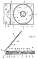
- the first embodiment of the data carrier packaging according to the invention shown in FIG. 2 comprises a preferably cylindrical receiving pin 7, which is produced independently of the receiving element 4, which is preferably made of solid cardboard and whose diameter is smaller than the central opening of a data carrier standardized in terms of its dimensions.
- the conical inner walls 14 connect the bottom of the recess 5 with the elevated parts 13 of the receiving element 4 and give the data carrier the possibility of inserting or removing movements with its peripheral edge region to below the level of the top surface 11.
- the data carrier 18 used is spaced on its circumference from the inner walls 14 and lies only on the survey surface 6 with the area that does not carry any data that can be called up.
- the data-carrying areas of a CD are thus suspended in a free-floating manner and cannot be scratched by unintentional contact with the data carrier packaging.
- the cover surfaces 11 have molded-on holding clips 17 which protrude beyond the inner walls 14 into the recess 5 in a substantially horizontal direction. If a data carrier, for example a CD, is used, it is centered via its central opening with the receiving pin 7 engaging in it. A slight press on the data carrier brings its peripheral edge regions to a level below the top surface 11 and thereby allows the holding clips 17 to spring out of the way around the periphery of the data carrier and to resume their starting position in an equally resilient manner.
- the data carrier used is prevented by the receiving pin from executing a movement parallel to the bottom of the recess 5 of the receiving element 4, so that the edge regions of the data carrier cannot just touch the inner walls 14.
- the dropping of the data carrier out of the packaging or the execution of an unintentional movement perpendicular to the bottom of the recess 5 of the receiving element 4 is prevented by the preferably three holding clips 17 integrated into the cover surfaces 11.
- more or fewer retaining clips 17 can also be provided.
- three holding clips have proven particularly useful, since at least one holding clip 17 is always on both sides of a randomly selected tilt axis that grazes the elevation surface 6 and therefore successfully prevents the data carrier from unintentionally tilting and thus preventing it from falling out.
- the shape of the receiving element 4 is supported by a correspondingly folded stabilizing element 19, preferably glued in its final shape.
- the receiving pin 7 extends through a recess in the receiving element 4 to the stabilizing element 19 to which it is glued.
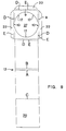
- the cover 2 comprises an inner part 20 with a handle opening 21.
- the inner part 20 is fastened to the outer part of the cover 2 by means of adhesive tabs 22 such that, for example, a brochure 23 or an "inlay card" can be inserted. Deviating from the illustration in FIG.
- the handle opening 21 lies on one of the other three sides of the cover 2, that is to say the “inlay card” corresponding to the viewing direction in FIG. 2a) from above can be inserted on the left or from below.
- a brochure comprising several pages, a “booklet” is inserted or fastened to the inner part 20 of the cover 2 or a pocket is dispensed with. It is clearly evident that the lid is folded around axes A and B when the data carrier packaging is opened or closed.
- the second embodiment of the data carrier packaging according to the invention shown in FIG. 3 comprises an at least approximately cylindrical receiving pin 7, which is made in one piece with the receiving element 4 and whose diameter is smaller than the central opening of a data carrier.
- the receiving pin 7 is filled by a support element 24 which extends to the stabilizing element 19 and is glued to it.
- the shape of the receiving element 4 is, according to the first embodiment, supported by a stabilizing element 19.
- the insertion, storage and removal of a data carrier in a packaging, according to this second embodiment, is identical to that of the first embodiment.
- the data carrier 18 used is spaced on its circumference from the inner walls 14 and lies only on the survey surface 6 with the area that does not carry any data that can be called up.
- a CD The data-carrying areas of a CD are thus suspended in a free-floating manner and cannot be scratched by unintentional contact with the data carrier packaging.
- the design of a pocket 26, which comprises an inner part 20 and a handle opening 21 as well as adhesive flaps 22, can be omitted by gluing the inner part 20 directly to the outer part of the cover 2.
- a brochure comprising several pages, a "booklet" is attached to the inner part 20 of the cover 2 or a pocket is dispensed with.
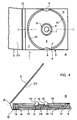
- the third embodiment of the data carrier packaging according to the invention shown in FIG. 4 comprises, in accordance with the second embodiment, a preferably cylindrical receptacle 7 which is produced in one piece with the receiving element 4, but whose diameter is practically identical to that of the central opening of a data carrier. Due to this approximately the same diameter, a frictional engagement is effective between an inserted data carrier 18 and the end faces 16 of the receiving pin 7, thanks to which the data carrier is prevented from falling out of the packaging. Holding clips can therefore be dispensed with.
- the data carrier 18 used is spaced on its circumference from the inner walls 14 and lies only on the survey surface 6 with the area that does not carry any data that can be called up.
- the data-carrying areas of a CD are thus suspended in a free-floating manner and cannot be scratched by unintentional contact with the data carrier packaging. If a data carrier, for example a CD, is inserted, it is centered and frictionally fixed via its central opening with the receiving pin 7, which essentially fills this central opening and engages in it.
- the data carrier used is prevented by the mounting pin 7 from executing a movement parallel to the bottom of the recess 5 of the mounting element 4 and perpendicular to it. When removing the data carrier, only the frictional force on the mounting pin has to be overcome.
- the shape of the receiving element 4 is, according to the first embodiment, supported by a stabilizing element 19. 4, the cover 2 can have a pocket 26 for an "inlay card” or a "booklet", the latter also being able to be fastened to the inner part 20 of the cover 2.
- the fourth embodiment of the data carrier packaging according to the invention shown in FIG. 5 comprises, in accordance with the third embodiment, a preferably cylindrical receptacle 7 which is produced in one piece with the receiving element 4 and whose diameter is practically identical to that of the central opening of a data carrier and causes a frictional engagement with it , thanks to which the data carrier is prevented from falling out of the packaging.
- the inserted data carrier 18 lies with the central area - which does not contain any retrievable data - on the survey surface 6 and is additionally supported in its peripheral area, which also does not contain retrievable data, by an intermediate stage 25, which is made in one piece with the inner walls 14.
- the insertion, storage and removal of a data carrier in a packaging, according to this fourth embodiment, is identical to that of the third embodiment.
- a fifth (not shown), simplified embodiment comprises elements of the first or second embodiment, according to FIG. 2 or FIG. 3, but the support element 24 is omitted.
- FIGS for the production of the data carrier packaging that can be used in one piece or their elements described.
- the specified Examples are by no means to be considered conclusive, variations in the process flows, materials and dimensions encompassed by the present invention.
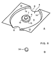
- FIG. 6a shows a receiving element 4, according to a second or third embodiment of the data carrier packaging according to the invention 1.
- the function of this receiving element 4 includes - as described above - the recording and the Locking of the product or data carrier to be packaged inside the data carrier packaging.
- Using the specially for it shaped elevation surface 6 becomes, for example CD held in floating position, making it accessible Data-bearing areas from scratch, abrasion and impact damage are protected.
- Blanks of such receiving elements 4 are according to a first method according to the invention flat cardboard material punched and grooved in one piece. Subsequently are these blanks (preferably with the same machine) in a deformation tool or a Thermoforming mold 28 conveyed and using pressure and Heat pressed in one piece into its final shape.
- a further embodiment for the production of receiving elements 4 comprises the following steps: A pulp is applied to a mold (not shown) and then the water contained in the pulp is drawn off. The blank is already in shape and needs to be dried. For a higher refinement of the material, the pulp can be pressed before drying, which increases the density of the material and its stability.
- Such further embodiments include a fiber casting method or a fiber spraying method, to which a pressing of the blanks preferably follows.
- FIG. 6b shows a support element 24, which is essentially a has a cylindrical shape, preferably by punching from a flat cardboard sheet (gray cardboard or the like) manufactured and with the stabilizing element 19 and the Receiving element 4 is glued.
- the function of this support element 24 includes the inclusion of a data carrier (cf. 2: locating pin 7 of the first embodiment) or the support of the one-piece with the receiving element 4, Locating pin 7.
- This locating pin 7 covers the support element 24 preferably completely and reduced its fatigue considerably. This extends the Lifetime or functional life of the combination of the journal / support element.
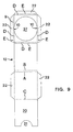
- the function of the stabilizing element shown in Fig. 7 19 includes the positioning of the receiving element 4 and the reinforcement of the entire packaging unit, whereby excellent protective properties, storability, stackability, Transport stability and lifespan of the data carrier packaging 1 is reached.
- the shape of the stabilizing element 19 is chosen so that all larger cavities the data carrier packaging 1 are essentially filled out.
- the stabilizing element 19 shown in the development is preferably made of flat corrugated cardboard sheets (E-Weile or F wave). or solid cardboard produced. For example a flat sheet of corrugated cardboard punched on a machine and grooved so that from the sheet one or more flat Stabilizing elements 19 arise. Punching the cutouts 27 and the recessed grips 8 can in the same operation be carried out.
- a one-piece according to the invention Stabilizing element 19 can also be used exclusively Presses and punches are manufactured.
- the function of the envelope element 12 shown in FIG. 8 includes the accommodation and encasing of all other elements or parts of the data carrier packaging according to the invention and of the product or data carrier to be packaged. As a result of the folding according to the invention, it forms a compact unit from the individual elements of the packaging.
- the part of the envelope element 12 designed as a cover 2 can have a compartment or a pocket 26 for receiving descriptions 23 or brochures referred to as "booklets" or "inlay cards”.
- the wrapping element 12 shown in the development is preferably produced from flat cardboard sheets. It can be printed and / or varnished in one or more colors. As a further finishing step, blind, relief or foil stamping can be provided, for example.
- the wrapping element 12 in addition to the cutouts 10 in the side walls 9, the wrapping element 12 also has 3 holding clips 17 molded onto the cover surfaces 11. Adhesive tabs 22 are formed on the side walls 9.
- the area of the enveloping element 12 which is provided as the inner lid part 20 or which adjoins it may also have adhesive tabs 22 in order to form a pocket 26 for a description 23 or an "inlay card". Like the handle opening 21, these are not shown here.
- envelope element 12 corresponds to that of the first or second embodiment.
- the envelope element 12 has Cutouts 10 in the side walls 9.
- adhesive tabs 22 are formed on the side walls 9 .
- the inner cover part 20 the area of the Envelope element 12 has or is a handle opening 21, to form a pocket 26 for a description 23 or an "inlay card", also provided with adhesive tabs 22.
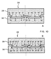
- the deep-drawing mold 28 shown as an example in FIG. 10 a) comprises the devices for pressing a receiving element 4 of a data carrier packaging 1 into the shape, according to a second and third embodiment.
- the deep-drawing mold 28 shown as an example in FIG. 10b) comprises the devices for pressing a receiving element 4 of a data carrier packaging 1 into the shape according to a fourth embodiment.
- the shaped surfaces of the punch 29 and the die 30 of the deep-drawing mold 28 were corresponding to the surfaces of the receiving element 4 to be pressed into the mold, with 5 ', 6', 7 ', 13', 14 ', 15', 16 'and 25' designated.
- a deep-drawing mold 28 for use in a method according to the invention for producing a data carrier packaging can comprise means for punching out a central recess, through which a support element 24 with the function of a receiving pin 7, according to a first embodiment of a data carrier packaging 1, is inserted can be.
- this special deep-drawing mold dispenses with the formation of a receiving pin 7 on the receiving element 4, the data carrier packaging 1 according to the invention therefore still has a receiving pin.
- the mono material used to manufacture the data carrier packaging 1 is, as is apparent from the description preferably flat material, the base material in essentially from generic natural fibers, mostly vegetable, of animal or mineral origin Dewatering a pulp slurry is formed. Optionally, small amounts of synthetic fibers can also be used be added. All parts of the packaging exist basically from recycled or recyclable and preferably also from biodegradable materials such as cardboard and paper, so this disk packaging 1 as a mono packaging may be referred to. Apply in some countries as mono packagings if they contain a foreign substance content of have less than 5%; nevertheless colors are preferred, Lacquers and adhesives used, which are environmentally friendly used and disposed of. In this respect mineral or synthetic fibers the requirements with regard to recyclability and biodegradability, they can can also be used as raw materials.
- the data carrier is not part of the invention.
- the cover 2 is first folded along the line C and - if a pocket 26 is provided - with the adhesive tabs 22, or otherwise glued over the entire surface.
- a stabilizing element 19 is folded backwards or forwards along the lines designated G or H in FIG. 7 and preferably glued over the entire surface.
- a receiving element 4 is glued to the stabilizing element 19.
- One locating pin 7 per locating element 4 is inserted through the corresponding recess in the locating element 4 and glued to the stabilizing element 19.
- This unit just formed is turned over and glued to the side of the sleeve 12 in which the round recess 27 is located.
- the three short side walls 9 are now erected along the lines D and folded with their adhesive flaps 22 along the lines E and glued to the back of the stabilizing element 19.
- the last step now is that the side on which the glued parts are located is completely folded over along lines E and D and glued over the entire surface.
- the resulting data carrier packaging 1 can be stacked and packaged in the open state or can be fed directly to the loading device with one data carrier each.
- the cover 2 is first folded along the line C and - if a pocket 26 is provided - with the adhesive tabs 22, or otherwise glued over the entire surface.
- a stabilizing element 19 is folded backwards or forwards along the lines designated G or H in FIG. 7 and preferably glued over the entire surface.
- One supporting element 24 per receiving element 4 is glued into the receiving pin on its underside.
- a receiving element 4 is glued to the stabilizing element 19. This unit just formed is turned over and the data carrier packaging 1, corresponding to that of the first embodiment, is completed.
- the resulting data carrier packaging 1 can be opened Condition stacked and packed or directly from the loading can be supplied with one data carrier each.
- Deviate from the described embodiments Data carrier packaging according to the invention, according to a sixth preferred embodiment (not shown), instead of the cover 2 with a further receiving element 4 all elements of the first to fifth embodiments, creating a packaging for two data carriers becomes.
- the receiving element 4 As an alternative adhesive connection between the receiving element 4, the support element 24, the stabilizing element 19 and / or the enveloping element 12 come in addition to the adhesive, for example gluing, welding or pressing into question.
Landscapes
- Packaging For Recording Disks (AREA)
- Liquid Crystal (AREA)
- Materials For Medical Uses (AREA)
- Ultra Sonic Daignosis Equipment (AREA)
- Endoscopes (AREA)
- Medicines Containing Material From Animals Or Micro-Organisms (AREA)
- Packaging Of Annular Or Rod-Shaped Articles, Wearing Apparel, Cassettes, Or The Like (AREA)
Description
Eine weitere Datenträgerverpackung ist aus EP 0 698 883 bekannt. Dieses Dokument wird als nächstliegender Stand der Technik betrachtet und offenbart eine Datenträgerverpackung, welche eine Klappkartonverpackung und eine Halterung aufweist, welche weitestgehend aus einem biologisch abbaubaren Material (mit zumindest 25 Gew.%, vorzugsweise 80 Gew.% Stärke) im Spritzgussverfahren gefertigt wird. Zur Erzielung eines elastisch federnden Aufnahmeteils (vgl. Segmente 61 in Fig. 3) mit einem ähnlichen Verhalten wie ein spritzgegossenes Kunststoffelement - als dessen direkter Ersatz es dienen soll - wird dieses Spritzguss-Element aus natürlichen Polymeren mit Zuschlägen, wie z.B. pflanzlichen Fasern, versetzt. Diese Verpackung wird der gestellten Aufgabe nicht gerecht, weil die Forderung nach einem einheitlichen Verpackungsmaterial nicht erfüllt ist: Der hohe Anteil von Stärke verhindert den biologischen Abbau nicht, die Wiederverwendung des Verpackungsmaterials wird dadurch aber zumindest erschwert.
Aus DE 44 00 048 ist eine Verpackung für eine CD in Form einer verschliessbaren Einlegehülle aus Papier bekannt. Damit der Datenträger aus dieser Verpackung herausgenommen werden kann, muss diese Hülle zumindest teilweise zerstört werden; sie weist zu diesem Zweck eine Perforation auf. Zur weiteren Aufbewahrung soll eine der üblichen Kunststoffschachteln dienen. Diese Verpackung wird der gestellten Aufgabe nicht gerecht, weil zur sicheren, vor Beschädigung schützenden Aufbewahrung eine Kunststoffschachtel benötigt wird und damit die Forderung nach dem einheitlichen Verpackungsmaterial nicht erfüllt ist. Zudem kommt eine Oberfläche der Verpackung mit den datentragenden Teilen der CD in Berührung, was vermieden werden soll.
- Fig. 1
- Eine 3D-Darstellung einer teilweise geöffneten Datenträgerverpackung, gemäss einer ersten bzw. zweiten Ausführungsform;
- Fig. 2
- Eine Datenträgerverpackung, gemäss einer ersten
Ausführungsform, welche in
- a) geöffnet in einer Draufsicht und in
- b) in einer leicht vergrösserten Schnittdarstellung, entsprechend der in a) mit X--X bezeichneten Linie, dargestellt ist;
- Fig. 3
- Eine Datenträgerverpackung, gemäss einer zweiten
Ausführungsform, welche in
- a) geöffnet in einer Draufsicht und in
- b) in einer leicht vergrösserten Schnittdarstellung, entsprechend der in a) mit X--X bezeichneten Linie, dargestellt ist;
- Fig. 4
- Eine Datenträgerverpackung, gemäss einer dritten
Ausführungsform, welche in
- a) geöffnet in einer Draufsicht und in
- b) in einer leicht vergrösserten Schnittdarstellung, entsprechend der in a) mit X--X bezeichneten Linie, dargestellt ist;
- Fig. 5
- Eine Datenträgerverpackung, gemäss einer vierten
Ausführungsform, welche in
- a) geöffnet in einer Draufsicht und in
- b) in einer leicht vergrösserten Schnittdarstellung, entsprechend der in a) mit X--X bezeichneten Linie, dargestellt ist;
- Fig. 6
- Eine 3D-Darstellung eines Aufnahmeelements, gemäss
einer zweiten bzw. dritten Ausführungsform, wobei
in
- a) das vorzugsweise mittels Tiefziehen hergestellte Aufnahmeelement und in
- b) ein Stützelement, abgebildet ist;
- Fig. 7
- Eine Draufsicht der Abwicklung eines Stabilisierungselements;
- Fig. 8
- Eine Draufsicht der Abwicklung eines Hüllelements, gemäss einer ersten bzw. zweiten Ausführungsform;
- Fig. 9
- Eine Draufsicht der Abwicklung eines Hüllelements, gemäss einer dritten bzw. vierten Ausführungsform;
- Fig. 10
- Eine Tiefziehform, gemäss einer zweiten, dritten bzw. vierten Ausführungsform einer Datenträgerverpackung.
Wird ein Datenträger, beispielsweise eine CD eingesetzt, so wird sie über ihre zentrale Öffnung mit dem in diese eingreifenden Aufnahmezapfen 7 zentriert. Ein leichtes Drücken auf den Datenträger bringt seine peripheren Randbereiche auf ein Niveau unterhalb der Deckfläche 11 und erlaubt dadurch den Halteclips 17 ein federndes Ausweichen um die Peripherie des Datenträgers herum und ein ebenso federndes Wiedereinnehmen ihrer Ausgangsposition. Der eingesetzte Datenträger wird, gemäss dieser ersten Ausführungsform, durch den Aufnahmezapfen am Ausführen einer zum Boden der Vertiefung 5 des Aufnahmeelements 4 parallelen Bewegung gehindert, so dass die Randbereiche des Datenträgers die Innenwände 14 gerade nicht berühren können. Das Herausfallen des Datenträgers aus der Verpackung bzw. das Ausführen einer unbeabsichtigten, zum Boden der Vertiefung 5 des Aufnahmeelements 4 senkrechten Bewegung wird durch die vorzugsweise drei, in die Deckflächen 11 integrierten, Halteclips 17 verhindert. In weiteren Ausführungsformen können auch mehr oder weniger Halteclips 17 vorgesehen sein. Besonders bewährt haben sich in der Praxis drei Halteclips, da immer mindestens ein Halteclip 17 auf beiden Seiten einer zufällig gewählten, die Erhebungsfläche 6 mindestens streifenden, Kippachse liegt und deshalb erfolgreich eine unbeabsichtigte Kippbewegung des Datenträgers und damit dessen Herausfallen verhindert. Beim Herausnehmen des Datenträgers sind wiederum drei Halteclips 17 bevorzugt, weil dann nur die Federkraft eines Halteclips 17 überwunden werden muss. Das Herausnehmen eines Datenträgers aus seiner Verpackung wird durch die vorhandenen Ausschnitte 10 in den Seitenwänden 9 und den Griffmulden 8 erheblich erleichtert.
Die Form des Aufnahmeelementes 4 wird durch ein entsprechend gefaltetes, vorzugsweise in seiner endgültigen Form verklebtes Stabilisierungselement 19 gestützt. Der Aufnahmezapfen 7 reicht durch eine Aussparung im Aufnahmeelement 4 bis auf das Stabilisierungselement 19, mit dem er verklebt ist. Der Deckel 2 umfasst einen Innenteil 20 mit einer Grifföffnung 21. Der Innenteil 20 ist mittels Klebelaschen 22 am Aussenteil des Deckels 2 so befestigt, dass beispielsweise eine Broschüre 23 bzw. eine "inlay card" eingeschoben werden kann. Abweichend von der Darstellung in Fig. 2 kann in einer weiteren Ausführungsform vorgesehen sein, dass die Grifföffnung 21 auf einer der anderen drei Seiten des Deckels 2 liegt, dass also die "inlay card" entsprechend der Blickrichtung in Fig. 2a) von oben, von links oder von unten eingeschoben werden kann. Des weiteren kann vorgesehen sein, dass eine mehrere Seiten umfassende Broschüre, ein "booklet" eingeschoben bzw. am Innenteil 20 des Deckels 2 befestigt ist bzw. auf eine Tasche verzichtet wird. Klar ersichtlich ist das Klappen des Deckels um die Achsen A und B beim Öffnen oder Schliessen der Datenträgerverpackung.
Das Einsetzen, Lagern und Herausnehmen eines Datenträgers in eine Verpackung, gemäss dieser zweiten Ausführungsform, ist mit jenem der ersten Ausführungsform identisch. Der eingesetzte Datenträger 18 ist an seinem Umfang von den Innenwänden 14 beabstandet und liegt nur mit dem Bereich, der keine abrufbaren Daten trägt auf der Erhebungsfläche 6 auf. Die datentragenden Bereiche einer CD sind also frei schwebend gelagert und können keine Schleifspuren durch unbeabsichtigte Kontakte mit der Datenträgerverpackung erleiden. Die Ausbildung einer Tasche 26, welche einen Innenteil 20 und eine Grifföffnung 21 sowie Klebelaschen 22 umfasst, kann in einer weiteren Ausführungsform weggelassen werden, indem der Innenteil 20 direkt mit dem Aussenteil des Deckels 2 verklebt wird. Des weiteren kann vorgesehen sein, dass eine mehrere Seiten umfassende Broschüre, ein "booklet" am Innenteil 20 des Deckels 2 befestigt ist bzw. auf eine Tasche verzichtet wird.
Wird ein Datenträger, beispielsweise eine CD eingesetzt, so wird sie über ihre zentrale Öffnung mit dem - diese zentrale Öffnung im wesentlichen ausfüllenden und in diese eingreifenden - Aufnahmezapfen 7 zentriert und reibschlüssig fixiert. Der eingesetzte Datenträger wird durch den Aufnahmezapfen 7 am Ausführen einer zum Boden der Vertiefung 5 des Aufnahmeelements 4 parallelen sowie einer dazu senkrechten Bewegung gehindert. Beim Herausnehmen des Datenträgers muss lediglich die Reibkraft am Aufnahmezapfen überwunden werden. Die Form des Aufnahmeelementes 4 wird, entsprechend der ersten Ausführungsform, durch ein Stabilisierungselement 19 gestützt.
Der Deckel 2 kann, abweichend von der Darstellung in Fig. 4, eine Tasche 26 für eine "inlay card" bzw. ein "booklet" aufweisen, wobei das letztere auch am Innenteil 20 des Deckels 2 befestigt sein kann.
Der Deckel 2 kann, abweichend von der Darstellung in Fig. 5, eine Tasche 26 für eine "inlay card" bzw. ein "booklet" aufweisen, wobei das letztere auch am Innenteil 20 des Deckels 2 befestigt sein kann.
Eine fünfte (nicht dargestellte), vereinfachte Ausführungsform umfasst Elemente der ersten bzw. zweiten Ausführungsform, gemäss Fig. 2 bzw. Fig. 3, wobei jedoch das Stützelement 24 weggelassen wird.
Ein Faserstoffbrei wird auf eine (nicht dargestellte) Form aufgebracht und dann das im Faserstoffbrei enthaltene Wasser abgezogen. Der Rohling ist damit bereits in Form gebracht und braucht noch getrocknet zu werden. Zur höheren Veredelung des Werkstoffes kann der Faserstoffbrei vor der Trocknung gepresst werden, wodurch sich die Dichte des Materials und dessen Stabilität erhöht. Solche weiteren Ausführungsformen umfassen ein Fasergussverfahren bzw. ein Faserspritzverfahren, an welche jeweils vorzugsweise ein Pressen der Rohlinge anschliesst.
Das in der Abwicklung dargestellte Hüllelement 12 wird vorzugsweise aus flachen Kartonbogen produziert. Es kann ein- oder mehrfarbig bedruckt und/oder lackiert werden. Als weiterer Veredelungsschritt kann beispielsweise eine Blind-, Relief- oder Folienprägung vorgesehen werden. Danach wird der Bogen auf einer Maschine gestanzt und gerillt, so dass aus einem Bogen eines oder mehrere dieser noch flächigen Hüllelemente 12 entstehen. Gemäss der ersten bzw. zweiten Ausführungsform der erfindungsgemässen Datenträgerverpackung weist das Hüllelement 12 neben den Ausschnitten 10 in den Seitenwänden 9 ausserdem 3, an die Deckflächen 11 angeformte, Halteclips 17 auf. An die Seitenwände 9 sind Klebelaschen 22 angeformt. Der als Deckelinnenteil 20 vorgesehene bzw. der gerade daran anschliessende Bereich des Hüllelements 12 kann, zwecks Bildung einer Tasche 26 für eine Beschreibung 23 bzw. eine "inlay card", ebenfalls Klebelaschen 22 aufweisen. Diese sind, wie die Grifföffnung 21, hier nicht dargestellt.
Die in Fig. 10b) als Beispiel dargestellte Tiefziehform 28 umfasst in einer zweiten Ausführungsform die Einrichtungen zum In-die-Form-Pressen eines Aufnahmeelementes 4 einer Datenträgerverpackung 1, gemäss einer vierten Ausführungsform. Die Formflächen des Stempels 29 und der Matrize 30 der Tiefziehform 28 wurden entsprechend den Flächen des damit in die Form zu pressenden Aufnahmeelementes 4, mit 5', 6', 7', 13', 14', 15', 16' und 25' bezeichnet.
Eine weitere (nicht dargestellte) Ausführungsform einer Tiefziehform 28 zur Verwendung in einem erfindungsgemässen Verfahren zur Herstellung einer Datenträgerverpackung kann Mittel zum Ausstanzen einer zentralen Aussparung umfassen, durch welche ein Stützelement 24 mit der Funktion eines Aufnahmezapfens 7, gemäss einer ersten Ausführungsform einer Datenträgerverpackung 1, gesteckt werden kann. Obwohl mit der Verwendung dieser speziellen Tiefziehform auf die Ausbildung eines Aufnahmezapfens 7 am Aufnahmeelement 4 verzichtet wird, weist die erfindungsgemässe Datenträgerverpackung 1 somit trotzdem einen Aufnahmezapfen auf.
Diese eben gebildete Einheit wird umgedreht und auf die Seite der Hülle 12 geklebt, in welcher sich die runde Aussparung 27 befindet. Die drei kurzen Seitenwände 9 werden nun entlang der Linien D aufgerichtet und mit ihren Klebelaschen 22 entlang der Linien E gefaltet und auf die Rückseite des Stabilisierungselementes 19 geklebt.
Die so entstandene Datenträgerverpackung 1 kann in offenem Zustande gestapelt und verpackt oder direkt der Beschickung mit je einem Datenträger zugeführt werden.
Diese eben gebildete Einheit wird umgedreht und die Datenträgerverpackung 1, entsprechend derjenigen der ersten Ausführungsform, fertiggestellt.
- Die Ausbildung einer Erhebungsfläche im Deckelinnenteil 20, welche einen Abstand zwischen Deckel und Datenträger bewirkt.
- Die zweiteilige Ausführung des Deckels 2, wobei die klappbaren Teile in der Grösse gleich oder verschieden sind.
- Einen zweiteiligen Deckel, dessen einer Teil durch den anderen Teil verriegelbar ist.
- Zwei gleich grosse Deckelteile, welche am bzw. im Aufnahmezapfen eingreifen und damit eine Verriegelung des Deckels bewirken.
- Eine Datenträgerverpackung, welche anstatt eines Aufnahmezapfens, zwei oder mehrere solche in einer Ebene umfasst. Damit wird eine handliche Datenträgerverpackung für beispielsweise drei bis sieben Mini Discs geschaffen, welche vorzugsweise in einer dichten Anordnung befestigt sind.
- Aufnahmezapfen 7, welche von der runden, zylindrischen Form abweichen. Sie können dabei gerade Stirnflächen 16 und einen polyedrischen oder kreuz- bzw. sternförmigen oder auch gekrümmte Stirnflächen 16 und einen zylindrisch gewellten Querschnitt aufweisen. Für diese Ausführungsformen speziell geeignet ist die Herstellung der Aufnahmeelemente 4 mittels Faserguss- bzw. Faserspritzverfahren.
- Halteclips 17 bzw. einen Aufnahmezapfen 7, welche einen Datenträger 18 am Ausführen einer Bewegung mit einer zum Boden der Vertiefung 5 senkrechten Komponente hindern.
Claims (23)
- Verfahren zur Herstellung einer Datenträgerverpackung (1) - zur Aufnahme mindestens eines im wesentlichen runden, eine zentrale Öffnung aufweisenden Datenträgers, insbesondere Compact Disc (CD), Video Disc (VD) oder Mini Disc (MD) - mit einem Deckel (2) und einem Aufnahmeteil (3), welcher ein Aufnahmeelement (4) und einen Aufnahmezapfen (7) zur Aufnahme und Zentrierung eines Datenträgers (18) an seiner zentralen Öffnung umfasst, gekennzeichnet durch das Anordnen eines Stabilisierungselementes (19) zum Ausfüllen von Hohlräumen sowie eines Hüllelementes (12) zur Aufnahme und Umhüllung aller anderen Elemente der Datenträgerverpackung (1) und des zu verpackenden Datenträgers, wobei alle Elemente aus gattungsgleichem Monomaterial zusammengefügt werden und wobei das Monomaterial aus zumindest 95 %, im wesentlichen gattungsleichen Naturfasern besteht.
- Verfahren nach Anspruch 1, dadurch gekennzeichnet, dass die Ausbildung dieses Aufnahmeelementes (4) mittels Tiefverformung bzw. die Herstellung dieses Aufnahmeelementes (4) mittels eines Faserguss- oder Faserspritzverfahrens erfolgt.
- Verfahren nach Anspruch 1 der 2, dadurch gekennzeichnet, dass der Aufnahmezapfen (7) einstückig mit dem Aufnahmeelement (4) ausgebildet, bzw. hergestellt wird.
- Verfahren nach einem der Ansprüche 1 bis 3, dadurch gekennzeichnet, dass der Aufnahmeteil (3) zudem ein Stützelement (24) zur Bildung bzw. Stützung des Aufnahmezapfens (7) umfasst, wobei alle Elemente untrennbar zusammengefügt werden.
- Verfahren nach einem der Ansprüche 1 bis 4, dadurch gekennzeichnet, dass das Aufnahmeelement (4) und/oder das Stützelement (24) und/oder das Stabilisierungselement (19) und/oder das Hüllelement (12) untereinander haft-verbunden werden.
- Verfahren nach einem der Ansprüche 1 bis 4, dadurch gekennzeichnet, dass das Aufnahmeelement (4) und/oder das Stützelement (24) und/oder das Stabilisierungselement (19) und/oder das Hüllelement (12) einstückig hergestellt werden.
- Verfahren nach einem der Ansprüche 1 bis 6, dadurch gekennzeichnet, dass zum einstückigen Herstellen des Aufnahmeelementes (4) eine Tiefziehform (28) verwendet wird.
- Verfahren nach Anspruch 7, dadurch gekennzeichnet, dass die Tiefziehform (28) Formflächen (5', 6', 13', 14' und 15') umfasst, mit welchen eine Vertiefung (5), eine Erhebungsfläche (6), zur Erhebungsfläche (6) konzentrische Innenwände (14), die in hochliegende Teile (13) übergehen sowie eine Erhebungsstufe (15) des Aufnahmeelementes (4) in Form gepresst werden.
- Verfahren nach Anspruch 7 oder 8, dadurch gekennzeichnet, dass die Tiefziehform Formflächen (6', 7' und 16') umfasst, mit welchen eine Erhebungsfläche (6) und ein zur Erhebungsfläche (6) konzentrischer Aufnahmezapfen (7) mit einer Stirnfläche (16) in Form gepresst werden.
- Verfahren nach einem der Ansprüche 7 bis 9, dadurch gekennzeichnet, dass die Tiefziehform eine Formfläche (25') umfasst, mit welcher im Bereich der Innenwände (14) des Aufnahmeelementes (4) Zwischenstufen (25) in Form gepresst werden.
- Datenträgerverpackung (1) in der Form einer Schachtel - zur Aufnahme mindestens eines im wesentlichen runden, eine zentrale Öffnung aufweisenden Datenträgers, insbesondere Compact Disc (CD), Video Disc (VD) oder Mini Disc (MD) - mit einem Deckel (2) und einem Aufnahmeteil (3), welcher ein Aufnahmeelement (4) mit einer Erhebungsfläche (6) zur Stützung eines Datenträgers (18) im zentralen Bereich, der keine abrufbaren Daten aufweist und einen Aufnahmezapfen (7) zur Aufnahme und Zentrierung dieses Datenträgers an seiner zentralen Öffnung umfasst, gekennzeichnet durch ein Stabilisierungselement (19) zum Ausfüllen von Hohlräumen sowie ein Hüllelement (12) zur Aufnahme und Umhüllung aller anderen Elemente der Datenträgerverpackung (1) und des zu verpackenden Datenträgers, wobei alle Elemente aus gattungsgleichem Monomaterial zusammengefügt sind und wobei das Monomaterial aus zumindest 95 %, im wesentlichen gattungsleichen Naturfasern besteht.
- Datenträgerverpackung nach Anspruch 11, dadurch gekennzeichnet, dass das Aufnahmeelement (4) mittels Tiefverformung ausgebildet bzw. mittels eines Faserguss- oder Faserspritzverfahrens hergestellt ist.
- Datenträgerverpackung nach Anspruch 11 oder 12, dadurch gekennzeichnet, dass der Aufnahmezapfen (7) einstückig mit dem Aufnahmeelement (4) ausgebildet, bzw. hergestellt ist.
- Datenträgerverpackung nach einem der Ansprüche 11 bis 13, dadurch gekennzeichnet, dass der Aufnahmeteil (3) zudem ein Stützelement (24) zur Bildung bzw. Stützung des Aufnahmezapfens (7) umfasst.
- Datenträgerverpackung nach einem der Ansprüche 11 bis 14, dadurch gekennzeichnet, dass der Aufnahmezapfen (7) so dimensioniert ist, dass er die zentrale Öffnung eines eingesetzten Datenträgers (18) im wesentlichen ausfüllt und diesen mindestens am Ausführen einer zum Boden einer Vertiefung (5) parallelen Bewegung hindert.
- Datenträgerverpackung nach einem der Ansprüche 14 oder 15, dadurch gekennzeichnet, dass das Stützelement (24) als Aufnahmezapfen (7) ausgebildet ist und durch eine Öffnung im Aufnahmeelement (4) reicht.
- Datenträgerverpackung nach einem der Ansprüche 11 bis 16, dadurch gekennzeichnet, dass das Hüllelement (12) Deckflächen (11) mit daran angeformten Halteclips (17) umfasst, welche einen Datenträger (18) am Ausführen einer Bewegung mit einer zum Boden der Vertiefung (5) senkrechten Komponente hindern.
- Datenträgerverpackung nach einem der Ansprüche 11 bis 16, dadurch gekennzeichnet, dass der Aufnahmezapfen (7) so dimensioniert ist, dass er diesen Datenträger (18) am Ausführen einer Bewegung mit einer zum Boden der Vertiefung (5) senkrechten Komponente hindert.
- Datenträgerverpackung nach Anspruch 17 oder 18, dadurch gekennzeichnet, dass das Aufnahmeelement (4) Innenwände (14) umfasst, welche einen eingesetzten Datenträger (18) an seinem Umfang nicht berühren und welchem hochliegende Teile (13) einstückig angeformt sind.
- Datenträgerverpackung nach Anspruch 19, dadurch gekennzeichnet, dass die Innenwände (14) den eingesetzten Datenträger (18) kreisförmig und konisch umschliessen.
- Datenträgerverpackung nach Anspruch 19 oder 20, dadurch gekennzeichnet, dass das Aufnahmeelement (4) im Bereich der Innenwände (14) eine Zwischenstufe (25) umfasst.
- Datenträgerverpackung nach einem der vorhergehenden Ansprüche 11 bis 21, dadurch gekennzeichnet, dass das Grundmaterial, aus dem die Datenträgerverpackung hergestellt ist, rezyklierte bzw. rezyklierbare und/oder biodegradierbare Stoffe umfasst.
- Datenträgerverpackung nach einem der vorhergehenden Ansprüche 11 bis 22, dadurch gekennzeichnet, dass der Deckel (2) eine Tasche (26) für eine Beschreibung (23) umfasst bzw. dass die Beschreibung (23) mit dem Deckel (2) unlösbar verbunden ist.
Applications Claiming Priority (4)
| Application Number | Priority Date | Filing Date | Title |
|---|---|---|---|
| CH142096 | 1996-06-05 | ||
| CH1420/96 | 1996-06-05 | ||
| CH142096 | 1996-06-05 | ||
| PCT/CH1997/000187 WO1997047008A1 (de) | 1996-06-05 | 1997-05-13 | Datenträgerverpackung |
Publications (2)
| Publication Number | Publication Date |
|---|---|
| EP0902948A1 EP0902948A1 (de) | 1999-03-24 |
| EP0902948B1 true EP0902948B1 (de) | 2000-08-16 |
Family
ID=4210049
Family Applications (1)
| Application Number | Title | Priority Date | Filing Date |
|---|---|---|---|
| EP97917983A Expired - Lifetime EP0902948B1 (de) | 1996-06-05 | 1997-05-13 | Datenträgerverpackung |
Country Status (9)
| Country | Link |
|---|---|
| EP (1) | EP0902948B1 (de) |
| JP (1) | JP2001503353A (de) |
| AT (1) | ATE195607T1 (de) |
| AU (1) | AU2630797A (de) |
| CZ (1) | CZ387698A3 (de) |
| DE (2) | DE59702212D1 (de) |
| ES (1) | ES2151257T3 (de) |
| HU (1) | HUP0004371A3 (de) |
| WO (1) | WO1997047008A1 (de) |
Families Citing this family (7)
| Publication number | Priority date | Publication date | Assignee | Title |
|---|---|---|---|---|
| JP3062617U (ja) | 1999-03-31 | 1999-10-08 | 株式会社不二コーン製作所 | Cdパッケ―ジ |
| US7257971B2 (en) | 2000-07-31 | 2007-08-21 | Autronics Plastics Inc. | Case with internal lock |
| DE20008746U1 (de) * | 2000-05-15 | 2000-08-03 | Sony Music Entertainment (Germany) GmbH, 60313 Frankfurt | Deckel mit Mitteln zum lösbaren Befestigen eines scheibenförmigen Datenträgers |
| DE20021924U1 (de) * | 2000-12-21 | 2001-05-10 | Irgang, Thorsten, 14089 Berlin | CD-Verpackung (Karte) |
| US7610782B2 (en) | 2003-02-07 | 2009-11-03 | Viva Onetime Limited | Lockable container having an integral and internal locking mechanism and methods of use |
| USD544743S1 (en) | 2005-09-26 | 2007-06-19 | Autronic Plastics, Inc. | Media storage case |
| KR102928210B1 (ko) * | 2023-09-11 | 2026-02-19 | 주식회사 신우 | 종이 재질의 cd케이스 및 이의 제조방법 |
Family Cites Families (6)
| Publication number | Priority date | Publication date | Assignee | Title |
|---|---|---|---|---|
| EP0503171A1 (de) * | 1991-03-12 | 1992-09-16 | Schwerdtle & Schantz GmbH | Schutzhülle für einen scheibenförmigen Aufzeichnungsträger |
| US5186327A (en) * | 1992-06-04 | 1993-02-16 | Mccafferty Daniel K | Compact disc retaining sheet |
| US5462158A (en) * | 1993-07-09 | 1995-10-31 | The C.W. Zumbiel Co. | Disc package |
| DE4400048A1 (de) * | 1994-01-03 | 1995-07-13 | Rotaform Druckerei Gmbh | Verpackung für eine Compact-Disc |
| US5772018A (en) * | 1994-03-30 | 1998-06-30 | Walch; Herbert | Packages for storage media and processes for production of same |
| EP0698883B1 (de) * | 1994-08-25 | 2000-06-14 | topac MultimediaPrint GmbH | Vepackung für ein scheibenförmiges Speichermedium |
-
1997
- 1997-05-13 AU AU26307/97A patent/AU2630797A/en not_active Abandoned
- 1997-05-13 ES ES97917983T patent/ES2151257T3/es not_active Expired - Lifetime
- 1997-05-13 EP EP97917983A patent/EP0902948B1/de not_active Expired - Lifetime
- 1997-05-13 DE DE59702212T patent/DE59702212D1/de not_active Expired - Fee Related
- 1997-05-13 DE DE19780519T patent/DE19780519D2/de not_active Expired - Lifetime
- 1997-05-13 JP JP50005698A patent/JP2001503353A/ja active Pending
- 1997-05-13 HU HU0004371A patent/HUP0004371A3/hu unknown
- 1997-05-13 CZ CZ983876A patent/CZ387698A3/cs unknown
- 1997-05-13 WO PCT/CH1997/000187 patent/WO1997047008A1/de not_active Ceased
- 1997-05-13 AT AT97917983T patent/ATE195607T1/de not_active IP Right Cessation
Also Published As
| Publication number | Publication date |
|---|---|
| DE59702212D1 (de) | 2000-09-21 |
| EP0902948A1 (de) | 1999-03-24 |
| AU2630797A (en) | 1998-01-05 |
| ATE195607T1 (de) | 2000-09-15 |
| ES2151257T3 (es) | 2000-12-16 |
| WO1997047008A1 (de) | 1997-12-11 |
| DE19780519D2 (de) | 1999-06-17 |
| JP2001503353A (ja) | 2001-03-13 |
| CZ387698A3 (cs) | 1999-04-14 |
| HUP0004371A3 (en) | 2001-08-28 |
| HUP0004371A2 (en) | 2001-03-28 |
Similar Documents
| Publication | Publication Date | Title |
|---|---|---|
| DE69416436T2 (de) | Aufbewahrungsbehälter für einen Aufzeichnungsträger | |
| DE69535021T2 (de) | Verpackung und etikettensatz für disketten | |
| DE69719198T2 (de) | Verpackungssystem zum aufnehmen, zurschaustellen und handhaben scheibenförmiger gegenstände | |
| DE69501268T2 (de) | Plattenlagerbehälter mit bedruckter Kartonschichten | |
| DE20300817U1 (de) | Faltschachtel | |
| EP0902948B1 (de) | Datenträgerverpackung | |
| EP0503171A1 (de) | Schutzhülle für einen scheibenförmigen Aufzeichnungsträger | |
| EP0455593A1 (de) | Verpackung für stossempfindliche Gebrauchsgüter | |
| DE602004002233T2 (de) | Präsentierschachtel mit Elementen zum Verhindern der Drehung und der Verschiebung eines in die Schachtel eingelegten Behälters | |
| EP0531654A1 (de) | Verkaufsverpackung für Gerätebatterien | |
| EP1195329A2 (de) | Faltschachtel mit schachteleinwärts versetztem Innenboden | |
| DE9103114U1 (de) | Schutzhülle für einen scheibenförmigen Aufzeichnungsträger | |
| DE19532162A1 (de) | Verpackung aus Karton und Verfahren zur Herstellung einer Verpackung | |
| DE10043850A1 (de) | Faltschachtel mit schachteleinwärts versetztem Boden | |
| WO1996015902A2 (de) | Verfahren und faltzuschnitt zur herstellung von faltschachteln | |
| DE202022106016U1 (de) | Verpackung und Verpackungszuschnitt | |
| DE9314008U1 (de) | Falttasche zur Verpackung | |
| DE9205433U1 (de) | Verpackungseinheit | |
| DE202020101928U1 (de) | Faltschachtel | |
| DE9303822U1 (de) | Verpackung für einen scheibenförmigen Aufzeichnungsträger | |
| DE202009013627U1 (de) | Verpackung für ein optisches Speichermedium | |
| DE20010914U1 (de) | Anordnung zur Beifügung von CD's in einer Zeitschrift | |
| DE4115389A1 (de) | Verfahren zur verpackung scheibenfoermiger aufzeichnungstraeger | |
| DE9109946U1 (de) | Verpackung, insbesondere Verkaufsverpackung | |
| DE29514901U1 (de) | Leicht zusammensetzbarer und gegen die Umgebung abgeschlossener Aufnahmebehälter |
Legal Events
| Date | Code | Title | Description |
|---|---|---|---|
| PUAI | Public reference made under article 153(3) epc to a published international application that has entered the european phase |
Free format text: ORIGINAL CODE: 0009012 |
|
| 17P | Request for examination filed |
Effective date: 19981128 |
|
| AK | Designated contracting states |
Kind code of ref document: A1 Designated state(s): AT BE CH DE ES FR GB IE IT LI LU NL SE |
|
| GRAG | Despatch of communication of intention to grant |
Free format text: ORIGINAL CODE: EPIDOS AGRA |
|
| 17Q | First examination report despatched |
Effective date: 19990430 |
|
| RTI1 | Title (correction) |
Free format text: PACKAGING FOR DATA MEDIA |
|
| GRAG | Despatch of communication of intention to grant |
Free format text: ORIGINAL CODE: EPIDOS AGRA |
|
| GRAH | Despatch of communication of intention to grant a patent |
Free format text: ORIGINAL CODE: EPIDOS IGRA |
|
| GRAH | Despatch of communication of intention to grant a patent |
Free format text: ORIGINAL CODE: EPIDOS IGRA |
|
| GRAA | (expected) grant |
Free format text: ORIGINAL CODE: 0009210 |
|
| AK | Designated contracting states |
Kind code of ref document: B1 Designated state(s): AT BE CH DE ES FR GB IE IT LI LU NL SE |
|
| REF | Corresponds to: |
Ref document number: 195607 Country of ref document: AT Date of ref document: 20000915 Kind code of ref document: T |
|
| REG | Reference to a national code |
Ref country code: CH Ref legal event code: EP |
|
| REG | Reference to a national code |
Ref country code: IE Ref legal event code: FG4D Free format text: GERMAN |
|
| REF | Corresponds to: |
Ref document number: 59702212 Country of ref document: DE Date of ref document: 20000921 |
|
| ITF | It: translation for a ep patent filed | ||
| REG | Reference to a national code |
Ref country code: CH Ref legal event code: NV Representative=s name: R. A. EGLI & CO. PATENTANWAELTE |
|
| GBT | Gb: translation of ep patent filed (gb section 77(6)(a)/1977) |
Effective date: 20001109 |
|
| ET | Fr: translation filed | ||
| REG | Reference to a national code |
Ref country code: ES Ref legal event code: FG2A Ref document number: 2151257 Country of ref document: ES Kind code of ref document: T3 |
|
| REG | Reference to a national code |
Ref country code: IE Ref legal event code: FD4D |
|
| PLBE | No opposition filed within time limit |
Free format text: ORIGINAL CODE: 0009261 |
|
| STAA | Information on the status of an ep patent application or granted ep patent |
Free format text: STATUS: NO OPPOSITION FILED WITHIN TIME LIMIT |
|
| 26N | No opposition filed | ||
| REG | Reference to a national code |
Ref country code: GB Ref legal event code: IF02 |
|
| PGFP | Annual fee paid to national office [announced via postgrant information from national office to epo] |
Ref country code: IE Payment date: 20020423 Year of fee payment: 6 |
|
| PGFP | Annual fee paid to national office [announced via postgrant information from national office to epo] |
Ref country code: NL Payment date: 20020430 Year of fee payment: 6 |
|
| PGFP | Annual fee paid to national office [announced via postgrant information from national office to epo] |
Ref country code: SE Payment date: 20020502 Year of fee payment: 6 |
|
| PGFP | Annual fee paid to national office [announced via postgrant information from national office to epo] |
Ref country code: ES Payment date: 20020516 Year of fee payment: 6 |
|
| PGFP | Annual fee paid to national office [announced via postgrant information from national office to epo] |
Ref country code: BE Payment date: 20020522 Year of fee payment: 6 |
|
| PGFP | Annual fee paid to national office [announced via postgrant information from national office to epo] |
Ref country code: LU Payment date: 20020605 Year of fee payment: 6 |
|
| PGFP | Annual fee paid to national office [announced via postgrant information from national office to epo] |
Ref country code: GB Payment date: 20030428 Year of fee payment: 7 |
|
| PGFP | Annual fee paid to national office [announced via postgrant information from national office to epo] |
Ref country code: AT Payment date: 20030506 Year of fee payment: 7 |
|
| PGFP | Annual fee paid to national office [announced via postgrant information from national office to epo] |
Ref country code: FR Payment date: 20030512 Year of fee payment: 7 |
|
| PG25 | Lapsed in a contracting state [announced via postgrant information from national office to epo] |
Ref country code: LU Free format text: LAPSE BECAUSE OF NON-PAYMENT OF DUE FEES Effective date: 20030513 Ref country code: IE Free format text: LAPSE BECAUSE OF NON-PAYMENT OF DUE FEES Effective date: 20030513 |
|
| PG25 | Lapsed in a contracting state [announced via postgrant information from national office to epo] |
Ref country code: SE Free format text: LAPSE BECAUSE OF NON-PAYMENT OF DUE FEES Effective date: 20030514 Ref country code: ES Free format text: LAPSE BECAUSE OF NON-PAYMENT OF DUE FEES Effective date: 20030514 |
|
| PG25 | Lapsed in a contracting state [announced via postgrant information from national office to epo] |
Ref country code: BE Free format text: LAPSE BECAUSE OF NON-PAYMENT OF DUE FEES Effective date: 20030531 |
|
| BERE | Be: lapsed |
Owner name: *PAWI VERPACKUNGEN A.G. Effective date: 20030531 |
|
| PG25 | Lapsed in a contracting state [announced via postgrant information from national office to epo] |
Ref country code: NL Free format text: LAPSE BECAUSE OF NON-PAYMENT OF DUE FEES Effective date: 20031201 |
|
| EUG | Se: european patent has lapsed | ||
| NLV4 | Nl: lapsed or anulled due to non-payment of the annual fee |
Effective date: 20031201 |
|
| REG | Reference to a national code |
Ref country code: IE Ref legal event code: MM4A |
|
| PG25 | Lapsed in a contracting state [announced via postgrant information from national office to epo] |
Ref country code: GB Free format text: LAPSE BECAUSE OF NON-PAYMENT OF DUE FEES Effective date: 20040513 Ref country code: AT Free format text: LAPSE BECAUSE OF NON-PAYMENT OF DUE FEES Effective date: 20040513 |
|
| REG | Reference to a national code |
Ref country code: ES Ref legal event code: FD2A Effective date: 20030514 |
|
| PGFP | Annual fee paid to national office [announced via postgrant information from national office to epo] |
Ref country code: CH Payment date: 20040825 Year of fee payment: 8 |
|
| GBPC | Gb: european patent ceased through non-payment of renewal fee |
Effective date: 20040513 |
|
| PG25 | Lapsed in a contracting state [announced via postgrant information from national office to epo] |
Ref country code: FR Free format text: LAPSE BECAUSE OF NON-PAYMENT OF DUE FEES Effective date: 20050131 |
|
| REG | Reference to a national code |
Ref country code: FR Ref legal event code: ST |
|
| PGFP | Annual fee paid to national office [announced via postgrant information from national office to epo] |
Ref country code: DE Payment date: 20050510 Year of fee payment: 9 |
|
| PG25 | Lapsed in a contracting state [announced via postgrant information from national office to epo] |
Ref country code: IT Free format text: LAPSE BECAUSE OF NON-PAYMENT OF DUE FEES;WARNING: LAPSES OF ITALIAN PATENTS WITH EFFECTIVE DATE BEFORE 2007 MAY HAVE OCCURRED AT ANY TIME BEFORE 2007. THE CORRECT EFFECTIVE DATE MAY BE DIFFERENT FROM THE ONE RECORDED. Effective date: 20050513 |
|
| PG25 | Lapsed in a contracting state [announced via postgrant information from national office to epo] |
Ref country code: LI Free format text: LAPSE BECAUSE OF NON-PAYMENT OF DUE FEES Effective date: 20050531 Ref country code: CH Free format text: LAPSE BECAUSE OF NON-PAYMENT OF DUE FEES Effective date: 20050531 |
|
| REG | Reference to a national code |
Ref country code: CH Ref legal event code: PL |
|
| PG25 | Lapsed in a contracting state [announced via postgrant information from national office to epo] |
Ref country code: DE Free format text: LAPSE BECAUSE OF NON-PAYMENT OF DUE FEES Effective date: 20061201 |