EP0902948B1 - Packaging for data media - Google Patents
Packaging for data media Download PDFInfo
- Publication number
- EP0902948B1 EP0902948B1 EP97917983A EP97917983A EP0902948B1 EP 0902948 B1 EP0902948 B1 EP 0902948B1 EP 97917983 A EP97917983 A EP 97917983A EP 97917983 A EP97917983 A EP 97917983A EP 0902948 B1 EP0902948 B1 EP 0902948B1
- Authority
- EP
- European Patent Office
- Prior art keywords
- data medium
- holding
- packaging
- data
- data carrier
- Prior art date
- Legal status (The legal status is an assumption and is not a legal conclusion. Google has not performed a legal analysis and makes no representation as to the accuracy of the status listed.)
- Expired - Lifetime
Links
Images


Classifications
-
- G—PHYSICS
- G11—INFORMATION STORAGE
- G11B—INFORMATION STORAGE BASED ON RELATIVE MOVEMENT BETWEEN RECORD CARRIER AND TRANSDUCER
- G11B33/00—Constructional parts, details or accessories not provided for in the other groups of this subclass
- G11B33/02—Cabinets; Cases; Stands; Disposition of apparatus therein or thereon
- G11B33/04—Cabinets; Cases; Stands; Disposition of apparatus therein or thereon modified to store record carriers
- G11B33/0405—Cabinets; Cases; Stands; Disposition of apparatus therein or thereon modified to store record carriers for storing discs
- G11B33/0433—Multiple disc containers
- G11B33/0444—Multiple disc containers for discs without cartridge
- G11B33/045—Multiple disc containers for discs without cartridge comprising centre hole locking means
Definitions
- the invention relates to packaging for holding thin, essentially round, at most damage-taking disks, which one - in their Dimensions standardized - central opening for insertion the spindle of a device that is used for retrieval or reading the stored data is suitable.
- Disk such as compact disks (CD), video disks (VD) or mini disks (MD) have precisely this shape, which is why the inventive Packaging for storage, display, sale and transporting such data carriers is particularly suitable.
- the invention relates to a method and a device for producing this packaging.
- CD packaging made of transparent plastic material in various embodiments is known. That packaging consists of one or more boxes for one or two CDs each. The boxes are connected to one another via hinges or with lids, so that each desired CD can be removed individually from the opened packaging. Inserts printed in one or more colors (so-called "inlay cards”), preferably made of paper, inform the interested buyer or user of the CD, for example, about the content or the possibilities thereof. The amount of information is often so large that a small booklet or booklet is placed in the packaging of the CD. Such CD packaging thus contains both plastic and paper.
- GB 2 272 685 ( D7 ) describes pocket-shaped containers which are folded from a piece of paper and have bellows-like side parts. Data carriers are inserted into these pockets from the side in an unusual way, so that loading with CDs that has already become standard has to be avoided. These bags can optionally be pushed into another container made of the same material, which ensures improved stability of the packaging. Nevertheless, the areas of the CD from which data can be called up are at least partially directly on the packaging, so that there are fears of grinding marks on the CD surface.
- the data-carrying surface of a CD is here at least partially brought into contact with the packaging, which in turn, together with the low stability, can be regarded as a disadvantage.
- This second group (D7 to D10) of data carrier packaging has significant disadvantages, above all due to the necessary alternative types of loading with CDs and the low stability.
- the goal of using monomaterial in US Pat. No. 5,427,236 ( D13 ) has also been insufficiently achieved because, despite largely avoiding plastic material, the central receiver for the CD still contains such material.
- the stability of the packaging also leaves something to be desired here.
- the object of the present invention is to provide a packaging for disk-shaped data carriers, in particular CDs, VDs or MDs, which combines the demand for the use of a uniform packaging material made of ecologically harmless and renewable raw material, economy, unbreakability, stability, printability and low weight the possibility of using CDs as standard, ie preferably automatically, and storing them in such a way that they only come into contact with the packaging in areas that do not contain any information that can be called up.
- Another data carrier packaging is known from EP 0 698 883.
- This document is considered to be the closest prior art and discloses a data carrier packaging which has a folding cardboard packaging and a holder which is largely manufactured from a biodegradable material (with at least 25% by weight, preferably 80% by weight starch) by injection molding.
- a biodegradable material with at least 25% by weight, preferably 80% by weight starch
- the direct replacement of which it is intended to serve this injection-molded element made of natural polymers is mixed with additives, such as vegetable fibers .
- This packaging does not live up to the task because the demand for a uniform packaging material is not fulfilled: the high proportion of starch does not prevent biodegradation, but it at least makes it difficult to reuse the packaging material.
- a cardboard packaging is known from WO 95/27286. She points a receiving part (with or without a lid) and a cover in which the receiving part - to prevent opening the cover or the data carrier falls out) is inserted.
- Another disk packaging from monomaterial is known from US 5,186,327. This exists from a recording part in which the data carrier is inserted and from a shell in which the receiving part is inserted (see there Figures 3 and 4). To take out of the data medium, the recording part must first again be pulled out of the envelope. These two packages do not do the job because through them the demand for standard loading a disk is not met.
- the task is accomplished by the method fulfilled according to claim 1.
- Preferred further training this inventive method result from the dependent claims 2 to 10.
- Preferred developments of this invention Packaging result from the dependent claims 12 to 23.
- the basic material of such Papers or boxes consist of natural fibers, which as Primary fibers in the form of cellulose from various Tree species or as secondary fibers by recycling waste paper and carton can be obtained.
- This according to the invention Packaging is, according to further aspects of the invention, produced by a method or an apparatus which processing by means of creasing, folding and gluing or the deep deformation of parts of the packaging. The Manufacturing is carried out simply, quickly and automatically and is therefore also economical.
- This packaging out A mono material is characterized by one - the one used Corresponding material paper or cardboard - unbreakability and printability.
- CDs can - Using an embodiment of the invention Packaging - using standard methods, e.g. automated used or loaded and stored so that the CDs only in areas that are not accessible Information touches the packaging come. These disks are from the bottom and the Cover inner surface spaced and are only in the central or peripheral part which does not have any retrievable data on a step-like surface.
- the mounting pin fixes the CD so that the data carrier is immobile in all directions of the packaging is held.
- the present data carrier packaging according to the invention compared to known CD packaging made of mixed material (first group) can biodegradability or biodegradability or compostability, use as renewable Energy source or recycling as a supplier of secondary or recycled fibers.
- first group biodegradability or biodegradability or compostability
- second group monomaterial
- D1 and D2 probably most widespread packaging
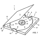
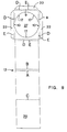
- the data carrier packaging 1 in FIG. 1 comprises a lid 2 and a recording part 3 for a disk that has something is raised, it is folded around the axes A or B.
- the receiving element 4 with a substantially round Well 5 and a concentric to it Survey is evident.
- a cylindrical locating pin 7 is preferably also concentric on the elevation surface 6 arranged.
- the outer diameter of the survey area 6 or the receiving pin 7 are somewhat smaller than the diameter of the central, non-data bearing area of a data carrier to be used or the central, standardized opening of a data carrier to be used, which is known to accommodate a drive spindle Data reader is used.
- recessed grips 8 are visible to facilitate them removing a disk.
- the side walls 9 of the data carrier packaging cut out In the area of the recessed grips 8 are the side walls 9 of the data carrier packaging cut out. Deviating from the illustration in FIG. 1 can in a further embodiment on the recessed grips 8 or at least partially omitted the cutouts 10 become.
- Cover surfaces 11 of the envelope element 12 cover the outer, high parts of the receiving element 4.
- the high parts of the receiving element 4 are vertical, preferably circular and slightly conical Inner walls 14 connected to the bottom of the recess 5 or molded in one piece. Likewise, it can preferably be conical trained survey level 15 and the at least approximately cylindrical receiving pin 7 with its substantially vertical end face 16 with the rest of the receiving element be connected or integrally formed.
- the top surfaces 11 have, according to a first or second embodiment, molded retaining clips 17, which in essentially horizontal direction over the inner walls 14 in the Survive depression 5. Deviating from that rounded off in FIG. 1 shown shape, the holding clips 17 a for example, have polygonal design.
- FIGS. 2 to 5 Embodiments of a box-shaped according to the invention Data carrier packaging presented. Of course this list is not exhaustive; are as well any combination of the features described below conceivable and are encompassed by the present invention.
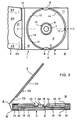
- the first embodiment of the data carrier packaging according to the invention shown in FIG. 2 comprises a preferably cylindrical receiving pin 7, which is produced independently of the receiving element 4, which is preferably made of solid cardboard and whose diameter is smaller than the central opening of a data carrier standardized in terms of its dimensions.
- the conical inner walls 14 connect the bottom of the recess 5 with the elevated parts 13 of the receiving element 4 and give the data carrier the possibility of inserting or removing movements with its peripheral edge region to below the level of the top surface 11.
- the data carrier 18 used is spaced on its circumference from the inner walls 14 and lies only on the survey surface 6 with the area that does not carry any data that can be called up.
- the data-carrying areas of a CD are thus suspended in a free-floating manner and cannot be scratched by unintentional contact with the data carrier packaging.
- the cover surfaces 11 have molded-on holding clips 17 which protrude beyond the inner walls 14 into the recess 5 in a substantially horizontal direction. If a data carrier, for example a CD, is used, it is centered via its central opening with the receiving pin 7 engaging in it. A slight press on the data carrier brings its peripheral edge regions to a level below the top surface 11 and thereby allows the holding clips 17 to spring out of the way around the periphery of the data carrier and to resume their starting position in an equally resilient manner.
- the data carrier used is prevented by the receiving pin from executing a movement parallel to the bottom of the recess 5 of the receiving element 4, so that the edge regions of the data carrier cannot just touch the inner walls 14.
- the dropping of the data carrier out of the packaging or the execution of an unintentional movement perpendicular to the bottom of the recess 5 of the receiving element 4 is prevented by the preferably three holding clips 17 integrated into the cover surfaces 11.
- more or fewer retaining clips 17 can also be provided.
- three holding clips have proven particularly useful, since at least one holding clip 17 is always on both sides of a randomly selected tilt axis that grazes the elevation surface 6 and therefore successfully prevents the data carrier from unintentionally tilting and thus preventing it from falling out.
- the shape of the receiving element 4 is supported by a correspondingly folded stabilizing element 19, preferably glued in its final shape.
- the receiving pin 7 extends through a recess in the receiving element 4 to the stabilizing element 19 to which it is glued.
- the cover 2 comprises an inner part 20 with a handle opening 21.
- the inner part 20 is fastened to the outer part of the cover 2 by means of adhesive tabs 22 such that, for example, a brochure 23 or an "inlay card" can be inserted. Deviating from the illustration in FIG.
- the handle opening 21 lies on one of the other three sides of the cover 2, that is to say the “inlay card” corresponding to the viewing direction in FIG. 2a) from above can be inserted on the left or from below.
- a brochure comprising several pages, a “booklet” is inserted or fastened to the inner part 20 of the cover 2 or a pocket is dispensed with. It is clearly evident that the lid is folded around axes A and B when the data carrier packaging is opened or closed.
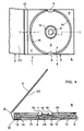
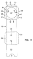
- the second embodiment of the data carrier packaging according to the invention shown in FIG. 3 comprises an at least approximately cylindrical receiving pin 7, which is made in one piece with the receiving element 4 and whose diameter is smaller than the central opening of a data carrier.
- the receiving pin 7 is filled by a support element 24 which extends to the stabilizing element 19 and is glued to it.
- the shape of the receiving element 4 is, according to the first embodiment, supported by a stabilizing element 19.
- the insertion, storage and removal of a data carrier in a packaging, according to this second embodiment, is identical to that of the first embodiment.
- the data carrier 18 used is spaced on its circumference from the inner walls 14 and lies only on the survey surface 6 with the area that does not carry any data that can be called up.
- a CD The data-carrying areas of a CD are thus suspended in a free-floating manner and cannot be scratched by unintentional contact with the data carrier packaging.
- the design of a pocket 26, which comprises an inner part 20 and a handle opening 21 as well as adhesive flaps 22, can be omitted by gluing the inner part 20 directly to the outer part of the cover 2.
- a brochure comprising several pages, a "booklet" is attached to the inner part 20 of the cover 2 or a pocket is dispensed with.
- the third embodiment of the data carrier packaging according to the invention shown in FIG. 4 comprises, in accordance with the second embodiment, a preferably cylindrical receptacle 7 which is produced in one piece with the receiving element 4, but whose diameter is practically identical to that of the central opening of a data carrier. Due to this approximately the same diameter, a frictional engagement is effective between an inserted data carrier 18 and the end faces 16 of the receiving pin 7, thanks to which the data carrier is prevented from falling out of the packaging. Holding clips can therefore be dispensed with.
- the data carrier 18 used is spaced on its circumference from the inner walls 14 and lies only on the survey surface 6 with the area that does not carry any data that can be called up.
- the data-carrying areas of a CD are thus suspended in a free-floating manner and cannot be scratched by unintentional contact with the data carrier packaging. If a data carrier, for example a CD, is inserted, it is centered and frictionally fixed via its central opening with the receiving pin 7, which essentially fills this central opening and engages in it.
- the data carrier used is prevented by the mounting pin 7 from executing a movement parallel to the bottom of the recess 5 of the mounting element 4 and perpendicular to it. When removing the data carrier, only the frictional force on the mounting pin has to be overcome.
- the shape of the receiving element 4 is, according to the first embodiment, supported by a stabilizing element 19. 4, the cover 2 can have a pocket 26 for an "inlay card” or a "booklet", the latter also being able to be fastened to the inner part 20 of the cover 2.
- the fourth embodiment of the data carrier packaging according to the invention shown in FIG. 5 comprises, in accordance with the third embodiment, a preferably cylindrical receptacle 7 which is produced in one piece with the receiving element 4 and whose diameter is practically identical to that of the central opening of a data carrier and causes a frictional engagement with it , thanks to which the data carrier is prevented from falling out of the packaging.
- the inserted data carrier 18 lies with the central area - which does not contain any retrievable data - on the survey surface 6 and is additionally supported in its peripheral area, which also does not contain retrievable data, by an intermediate stage 25, which is made in one piece with the inner walls 14.
- the insertion, storage and removal of a data carrier in a packaging, according to this fourth embodiment, is identical to that of the third embodiment.
- a fifth (not shown), simplified embodiment comprises elements of the first or second embodiment, according to FIG. 2 or FIG. 3, but the support element 24 is omitted.
- FIGS for the production of the data carrier packaging that can be used in one piece or their elements described.
- the specified Examples are by no means to be considered conclusive, variations in the process flows, materials and dimensions encompassed by the present invention.
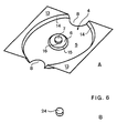
- FIG. 6a shows a receiving element 4, according to a second or third embodiment of the data carrier packaging according to the invention 1.
- the function of this receiving element 4 includes - as described above - the recording and the Locking of the product or data carrier to be packaged inside the data carrier packaging.
- Using the specially for it shaped elevation surface 6 becomes, for example CD held in floating position, making it accessible Data-bearing areas from scratch, abrasion and impact damage are protected.
- Blanks of such receiving elements 4 are according to a first method according to the invention flat cardboard material punched and grooved in one piece. Subsequently are these blanks (preferably with the same machine) in a deformation tool or a Thermoforming mold 28 conveyed and using pressure and Heat pressed in one piece into its final shape.
- a further embodiment for the production of receiving elements 4 comprises the following steps: A pulp is applied to a mold (not shown) and then the water contained in the pulp is drawn off. The blank is already in shape and needs to be dried. For a higher refinement of the material, the pulp can be pressed before drying, which increases the density of the material and its stability.
- Such further embodiments include a fiber casting method or a fiber spraying method, to which a pressing of the blanks preferably follows.
- FIG. 6b shows a support element 24, which is essentially a has a cylindrical shape, preferably by punching from a flat cardboard sheet (gray cardboard or the like) manufactured and with the stabilizing element 19 and the Receiving element 4 is glued.
- the function of this support element 24 includes the inclusion of a data carrier (cf. 2: locating pin 7 of the first embodiment) or the support of the one-piece with the receiving element 4, Locating pin 7.
- This locating pin 7 covers the support element 24 preferably completely and reduced its fatigue considerably. This extends the Lifetime or functional life of the combination of the journal / support element.
- the function of the stabilizing element shown in Fig. 7 19 includes the positioning of the receiving element 4 and the reinforcement of the entire packaging unit, whereby excellent protective properties, storability, stackability, Transport stability and lifespan of the data carrier packaging 1 is reached.
- the shape of the stabilizing element 19 is chosen so that all larger cavities the data carrier packaging 1 are essentially filled out.
- the stabilizing element 19 shown in the development is preferably made of flat corrugated cardboard sheets (E-Weile or F wave). or solid cardboard produced. For example a flat sheet of corrugated cardboard punched on a machine and grooved so that from the sheet one or more flat Stabilizing elements 19 arise. Punching the cutouts 27 and the recessed grips 8 can in the same operation be carried out.
- a one-piece according to the invention Stabilizing element 19 can also be used exclusively Presses and punches are manufactured.
- the function of the envelope element 12 shown in FIG. 8 includes the accommodation and encasing of all other elements or parts of the data carrier packaging according to the invention and of the product or data carrier to be packaged. As a result of the folding according to the invention, it forms a compact unit from the individual elements of the packaging.
- the part of the envelope element 12 designed as a cover 2 can have a compartment or a pocket 26 for receiving descriptions 23 or brochures referred to as "booklets" or "inlay cards”.
- the wrapping element 12 shown in the development is preferably produced from flat cardboard sheets. It can be printed and / or varnished in one or more colors. As a further finishing step, blind, relief or foil stamping can be provided, for example.
- the wrapping element 12 in addition to the cutouts 10 in the side walls 9, the wrapping element 12 also has 3 holding clips 17 molded onto the cover surfaces 11. Adhesive tabs 22 are formed on the side walls 9.
- the area of the enveloping element 12 which is provided as the inner lid part 20 or which adjoins it may also have adhesive tabs 22 in order to form a pocket 26 for a description 23 or an "inlay card". Like the handle opening 21, these are not shown here.
- envelope element 12 corresponds to that of the first or second embodiment.
- the envelope element 12 has Cutouts 10 in the side walls 9.
- adhesive tabs 22 are formed on the side walls 9 .
- the inner cover part 20 the area of the Envelope element 12 has or is a handle opening 21, to form a pocket 26 for a description 23 or an "inlay card", also provided with adhesive tabs 22.
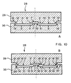
- the deep-drawing mold 28 shown as an example in FIG. 10 a) comprises the devices for pressing a receiving element 4 of a data carrier packaging 1 into the shape, according to a second and third embodiment.
- the deep-drawing mold 28 shown as an example in FIG. 10b) comprises the devices for pressing a receiving element 4 of a data carrier packaging 1 into the shape according to a fourth embodiment.
- the shaped surfaces of the punch 29 and the die 30 of the deep-drawing mold 28 were corresponding to the surfaces of the receiving element 4 to be pressed into the mold, with 5 ', 6', 7 ', 13', 14 ', 15', 16 'and 25' designated.
- a deep-drawing mold 28 for use in a method according to the invention for producing a data carrier packaging can comprise means for punching out a central recess, through which a support element 24 with the function of a receiving pin 7, according to a first embodiment of a data carrier packaging 1, is inserted can be.
- this special deep-drawing mold dispenses with the formation of a receiving pin 7 on the receiving element 4, the data carrier packaging 1 according to the invention therefore still has a receiving pin.
- the mono material used to manufacture the data carrier packaging 1 is, as is apparent from the description preferably flat material, the base material in essentially from generic natural fibers, mostly vegetable, of animal or mineral origin Dewatering a pulp slurry is formed. Optionally, small amounts of synthetic fibers can also be used be added. All parts of the packaging exist basically from recycled or recyclable and preferably also from biodegradable materials such as cardboard and paper, so this disk packaging 1 as a mono packaging may be referred to. Apply in some countries as mono packagings if they contain a foreign substance content of have less than 5%; nevertheless colors are preferred, Lacquers and adhesives used, which are environmentally friendly used and disposed of. In this respect mineral or synthetic fibers the requirements with regard to recyclability and biodegradability, they can can also be used as raw materials.
- the data carrier is not part of the invention.
- the cover 2 is first folded along the line C and - if a pocket 26 is provided - with the adhesive tabs 22, or otherwise glued over the entire surface.
- a stabilizing element 19 is folded backwards or forwards along the lines designated G or H in FIG. 7 and preferably glued over the entire surface.
- a receiving element 4 is glued to the stabilizing element 19.
- One locating pin 7 per locating element 4 is inserted through the corresponding recess in the locating element 4 and glued to the stabilizing element 19.
- This unit just formed is turned over and glued to the side of the sleeve 12 in which the round recess 27 is located.
- the three short side walls 9 are now erected along the lines D and folded with their adhesive flaps 22 along the lines E and glued to the back of the stabilizing element 19.
- the last step now is that the side on which the glued parts are located is completely folded over along lines E and D and glued over the entire surface.
- the resulting data carrier packaging 1 can be stacked and packaged in the open state or can be fed directly to the loading device with one data carrier each.
- the cover 2 is first folded along the line C and - if a pocket 26 is provided - with the adhesive tabs 22, or otherwise glued over the entire surface.
- a stabilizing element 19 is folded backwards or forwards along the lines designated G or H in FIG. 7 and preferably glued over the entire surface.
- One supporting element 24 per receiving element 4 is glued into the receiving pin on its underside.
- a receiving element 4 is glued to the stabilizing element 19. This unit just formed is turned over and the data carrier packaging 1, corresponding to that of the first embodiment, is completed.
- the resulting data carrier packaging 1 can be opened Condition stacked and packed or directly from the loading can be supplied with one data carrier each.
- Deviate from the described embodiments Data carrier packaging according to the invention, according to a sixth preferred embodiment (not shown), instead of the cover 2 with a further receiving element 4 all elements of the first to fifth embodiments, creating a packaging for two data carriers becomes.
- the receiving element 4 As an alternative adhesive connection between the receiving element 4, the support element 24, the stabilizing element 19 and / or the enveloping element 12 come in addition to the adhesive, for example gluing, welding or pressing into question.
Landscapes
- Packaging For Recording Disks (AREA)
- Packaging Of Annular Or Rod-Shaped Articles, Wearing Apparel, Cassettes, Or The Like (AREA)
- Liquid Crystal (AREA)
- Materials For Medical Uses (AREA)
- Ultra Sonic Daignosis Equipment (AREA)
- Endoscopes (AREA)
- Medicines Containing Material From Animals Or Micro-Organisms (AREA)
Abstract
Description
Die Erfindung betrifft in einem ersten Aspekt eine Verpackung zur Aufnahme von dünnen, im wesentlichen runden, allenfalls schadennehmenden Scheiben, welche eine - in ihren Dimensionen genormte - zentrale Öffnung, die zum Einführen der Spindel eines Gerätes, welches zum Abrufen bzw. Lesen der gespeicherten Daten geeignet ist, aufweisen. Datenträger wie Compact Disks (CD), Video Disks (VD) oder Mini Disks (MD) weisen gerade diese Form auf, weshalb sich die erfindungsgemässe Verpackung zum Lagern, Ausstellen, Verkaufen und Transportieren insbesondere solcher Datenträger eignet. In einem zweiten Aspekt betrifft die Erfindung ein Verfahren und eine Vorrichtung zur Herstellung dieser Verpackung.In a first aspect, the invention relates to packaging for holding thin, essentially round, at most damage-taking disks, which one - in their Dimensions standardized - central opening for insertion the spindle of a device that is used for retrieval or reading the stored data is suitable. Disk such as compact disks (CD), video disks (VD) or mini disks (MD) have precisely this shape, which is why the inventive Packaging for storage, display, sale and transporting such data carriers is particularly suitable. In a second aspect, the invention relates to a method and a device for producing this packaging.
Bekannt sind vor allem, wie z.B. in EP 0 420 350 (D1) beschrieben, CD-Verpackungen aus durchsichtigem Kunststoffmaterial in verschiedenen Ausführungsformen. Jene Verpackung besteht aus einer oder mehreren Schachteln für je eine oder zwei CDs. Die Schachteln sind über Gelenke untereinander bzw. mit Deckeln verbunden, so dass jede gewünschte CD einzeln der aufgeklappten Verpackung entnommen werden kann. Ein- oder mehrfarbig bedruckte Einlagen (sogenannte "inlay cards") - vorzugsweise aus Papier - informieren den interessierten Käufer bzw. Anwender der CD z.B. über den Inhalt bzw. die Möglichkeiten derselben. Oft ist der Umfang der Informationen so gross, dass ein kleines Heft oder Büchlein (ein sogenanntes "booklet") in die Verpackung der CD gelegt wird. Derartige CD-Verpackungen enthalten also sowohl Kunststoff als auch Papier.Above all, as described for example in EP 0 420 350 ( D1 ), CD packaging made of transparent plastic material in various embodiments is known. That packaging consists of one or more boxes for one or two CDs each. The boxes are connected to one another via hinges or with lids, so that each desired CD can be removed individually from the opened packaging. Inserts printed in one or more colors (so-called "inlay cards"), preferably made of paper, inform the interested buyer or user of the CD, for example, about the content or the possibilities thereof. The amount of information is often so large that a small booklet or booklet is placed in the packaging of the CD. Such CD packaging thus contains both plastic and paper.
Die zunehmende Einsicht, dass solche Datenträgerverpackungen in riesiger Zahl - nicht nur möglichst umweltschonend hergestellt - sondern auch ebenso entsorgt werden müssen, führte mehr und mehr zur Suche nach Ersatzmaterialien für die aus nicht-erneuerbaren Rohstoffen hergestellten Kunststoff Verpackungen. So wurde der Plastikanteil der CD-Verpackungen beispielsweise auf einen relativ stabilen Boden (US 5,307, 927, D2; US 5, 236,081, D3) reduziert, der - verbunden mit der Verpackung aus Papier oder Karton - die Funktion der Aufnahme einer CD erfüllt. Eine andere Schrift (US 5,379, 890, D4) beschreibt einen ebenfalls stabilen Kunststoffträger, der in eine aus einem Stück gefaltete Kartonschachtel eingeschoben werden kann. In einer weiteren Schrift (US 5, 421,453, D5) wird - als weitere mögliche Reduktion des Kunststoffanteils an der Verpackung - eine dünne, flexible Kunststoffeinlage für eine aus einem Stück gefaltete Kartonschachtel beschrieben. Die EP 0 493 983 (D6) schliesslich schlägt vor, kleine runde Scheiben, welche im wesentlichen nur die Auflage und den Schnappmechanismus - welche beide z.B. aus D1 bekannt sind - für die Aufnahme der CD umfassen, auf eine gefaltete Papier- oder Kartonhülle zu kleben. Allen diesen Veröffentlichungen einer ersten Gruppe (D1 bis D6) ist jedoch gemeinsam, dass sie aus dem nicht nachwachsenden Rohstoff Erdöl produzierten Material Kunststoff bzw. aus einer Kombination von Kunststoff und Papier bestehen. Setzt man sich die Wiederverwertung des zur CD-Verpackung verwendeten Materials zum Ziel, so müssen die Materialien getrennt werden, was einen enormen technischen und finanziellen Aufwand bedeuten kann.The increasing insight that such data carrier packaging in huge numbers - not only as environmentally friendly as possible - but also has to be disposed of, led more and more to the search for replacement materials for plastic packaging made from non-renewable raw materials. For example, the plastic part of the CD packaging was reduced to a relatively stable base (US 5,307,927, D2 ; US 5, 236,081, D3 ), which - combined with the paper or cardboard packaging - fulfills the function of holding a CD. Another document (US 5,379,890, D4 ) describes a likewise stable plastic carrier which can be inserted into a cardboard box folded from one piece. Another document (US Pat. No. 5,421,453, D5 ) describes - as a further possible reduction in the proportion of plastic in the packaging - a thin, flexible plastic insert for a cardboard box folded from one piece. Finally, EP 0 493 983 ( D6 ) proposes to glue small round disks, which essentially only comprise the support and the snap mechanism - both of which are known, for example, from D1 - for holding the CD, onto a folded paper or cardboard sleeve . However, all these publications of a first group (D1 to D6) have in common that they consist of the non-renewable raw material petroleum, plastic, or a combination of plastic and paper. If the goal is to recycle the material used for CD packaging, the materials must be separated, which can mean enormous technical and financial expense.
Verpackungen einer zweiten Gruppe aus nur einem Material,
sogenanntem Monomaterial, wurden deshalb vorgeschlagen. Neben
dem Vorteil einer einfachen Entsorgung bzw. Wiederverwertung
brachte dies auch eine erhebliche Gewichtseinsparung
des Verpackungsmaterials mit sich. GB 2 272 685 (D7) beschreibt
aus einem Stück Papier gefaltete, balgähnliche Seitenteile
aufweisende, taschenförmige Behälter. In diese Taschen
werden Datenträger in unüblicher Weise seitlich eingeschoben,
so dass auf eine bereits zum Standard gewordene Beschickung
mit CDs verzichtet werden muss. Diese Taschen können
wahlweise in einen weiteren, aus dem gleichen Material
hergestellten Behälter geschoben werden, was eine verbesserte
Stabilität der Verpackung gewährleistet. Trotzdem liegen
die Bereiche der CD, von denen Daten abgerufen werden
können, mindestens teilweise direkt auf der Verpackung auf,
so dass Schleifspuren in der CD-Oberfläche befürchtet werden
müssen. Weitere und vor allem stabilere Verpackungen aus
Monomaterial sind aus WO 93/21086 (D8) und US 5,422,875 (D9)
bekannt. Diese halten - im Unterschied zu der vorher beschriebenen
D7 - die CDs seitlich am Umfang über speziell
ausgebildete Auflagen oder Nocken fest, damit die Oberflächenbereiche
der CD, welche abrufbare Daten trägt, nicht direkt
mit der Verpackung in Berührung kommen kann. Weil in D8
eine Art Schnappverschluss den Rand der CD festhält und in
D9 die Datenträger seitlich eingeschoben werden müssen,
kommt auch hier eine automatisierte Standardbeschickung der
Verpackung kaum in Frage. Extrem leicht ausgebildet ist die,
aus nur einem Faltblatt Papier bestehende Verpackung in US
5,472,083 (D10). Die datentragende Oberfläche einer CD wird
hier mindestens teilweise mit der Verpackung in Berührung
gebracht, was wiederum zusammen mit der geringen Stabilität
als Nachteil gewertet werden kann. Diese zweite Gruppe (D7
bis D10) von Datenträgerverpackungen weist vor allem durch
die notwendigen, alternativen Beschickungsarten mit CDs bzw.
die geringe Stabilität wesentliche Nachteile auf. Ebenfalls
ungenügend erreicht ist das Ziel der Verwendung von Monomaterial
in US 5,427,236 (D13), weil, trotz weitgehendem Vermeiden
von Kunststoffmaterial, der zentrale Aufnehmer für
die CD immer noch solches umfasst. Zudem lässt auch hier die
Stabilität der Verpackung zu wünschen übrig.Packaging of a second group of only one material, so-called monomaterial, has therefore been proposed. In addition to the advantage of simple disposal or recycling, this also resulted in considerable weight savings in the packaging material.
Die Aufgabe der vorliegenden Erfindung besteht darin, eine
Verpackung für scheibenförmige Datenträger, insbesondere
CDs, VDs oder MDs bereitzustellen, welche die Forderung nach
der Verwendung eines einheitlichen Verpackungsmaterials aus
ökologisch unbedenklichem und nachwachsendem Rohstoff, Wirtschaftlichkeit,
Unzerbrechlichkeit, Stabilität, Bedruckbarkeit
und geringem Gewicht verbindet mit der Möglichkeit, CDs
standardmässig, d.h. vorzugsweise automatisiert, einzusetzen
und diese so zu lagern, dass sie ausschliesslich in Bereichen,
welche keine abrufbaren Informationen tragen, mit der
Verpackung in Berührung kommen.
Eine weitere Datenträgerverpackung ist aus EP 0 698 883 bekannt.
Dieses Dokument wird als nächstliegender Stand der
Technik betrachtet und offenbart eine Datenträgerverpackung,
welche eine Klappkartonverpackung und eine Halterung aufweist,
welche weitestgehend aus einem biologisch abbaubaren
Material (mit zumindest 25 Gew.%, vorzugsweise 80 Gew.%
Stärke) im Spritzgussverfahren gefertigt wird. Zur Erzielung
eines elastisch federnden Aufnahmeteils (vgl. Segmente 61 in
Fig. 3) mit einem ähnlichen Verhalten wie ein spritzgegossenes
Kunststoffelement - als dessen direkter Ersatz es
dienen soll - wird dieses Spritzguss-Element aus natürlichen
Polymeren mit Zuschlägen, wie z.B. pflanzlichen Fasern,
versetzt. Diese Verpackung wird der gestellten Aufgabe nicht
gerecht, weil die Forderung nach einem einheitlichen
Verpackungsmaterial nicht erfüllt ist: Der hohe Anteil von
Stärke verhindert den biologischen Abbau nicht, die Wiederverwendung
des Verpackungsmaterials wird dadurch aber zumindest
erschwert.
Aus DE 44 00 048 ist eine Verpackung für eine CD in Form
einer verschliessbaren Einlegehülle aus Papier bekannt. Damit
der Datenträger aus dieser Verpackung herausgenommen
werden kann, muss diese Hülle zumindest teilweise zerstört
werden; sie weist zu diesem Zweck eine Perforation auf. Zur
weiteren Aufbewahrung soll eine der üblichen Kunststoffschachteln
dienen. Diese Verpackung wird der gestellten
Aufgabe nicht gerecht, weil zur sicheren, vor Beschädigung
schützenden Aufbewahrung eine Kunststoffschachtel benötigt
wird und damit die Forderung nach dem einheitlichen Verpackungsmaterial
nicht erfüllt ist. Zudem kommt eine Oberfläche
der Verpackung mit den datentragenden Teilen der CD
in Berührung, was vermieden werden soll.The object of the present invention is to provide a packaging for disk-shaped data carriers, in particular CDs, VDs or MDs, which combines the demand for the use of a uniform packaging material made of ecologically harmless and renewable raw material, economy, unbreakability, stability, printability and low weight the possibility of using CDs as standard, ie preferably automatically, and storing them in such a way that they only come into contact with the packaging in areas that do not contain any information that can be called up.
Another data carrier packaging is known from EP 0 698 883. This document is considered to be the closest prior art and discloses a data carrier packaging which has a folding cardboard packaging and a holder which is largely manufactured from a biodegradable material (with at least 25% by weight, preferably 80% by weight starch) by injection molding. In order to achieve an elastically resilient receiving part (see segments 61 in FIG. 3) with behavior similar to an injection-molded plastic element - the direct replacement of which it is intended to serve - this injection-molded element made of natural polymers is mixed with additives, such as vegetable fibers . This packaging does not live up to the task because the demand for a uniform packaging material is not fulfilled: the high proportion of starch does not prevent biodegradation, but it at least makes it difficult to reuse the packaging material.
From DE 44 00 048 a packaging for a CD in the form of a closable insert sleeve made of paper is known. In order for the data carrier to be removed from this packaging, this sleeve must be at least partially destroyed; for this purpose it has a perforation. One of the usual plastic boxes should be used for further storage. This packaging does not do justice to the task at hand, because a plastic box is required for safe, protective storage and therefore the requirement for the uniform packaging material is not met. In addition, a surface of the packaging comes into contact with the data-carrying parts of the CD, which should be avoided.
Eine Kartonverpackung ist aus WO 95/27286 bekannt. Sie weist einen Aufnahmeteil (mit oder ohne Deckel) und eine Hülle auf, in welche der Aufnahmeteil - zum Verhindern des Aufklappens des Deckels bzw. des Herausfallens des Datenträgers) eingeschoben wird. Eine weitere Datenträgerverpackung aus Monomaterial ist aus US 5,186,327 bekannt. Diese besteht aus einem Aufnahmeteil, in den der Datenträger eingesetzt wird und aus einer Hülle, in welche der Aufnahmeteil eingeschoben wird (siehe dort Figuren 3 und 4). Zum Herausnehmen des Datenträgers muss der Aufnahmeteil zuerst wieder aus der Hülle herausgezogen werden. Diese beiden Verpackungen werden der gestellten Aufgabe nicht gerecht, weil durch sie die Forderung nach standardmässiger Beladung mit einem Datenträger nicht erfüllt wird.A cardboard packaging is known from WO 95/27286. She points a receiving part (with or without a lid) and a cover in which the receiving part - to prevent opening the cover or the data carrier falls out) is inserted. Another disk packaging from monomaterial is known from US 5,186,327. This exists from a recording part in which the data carrier is inserted and from a shell in which the receiving part is inserted (see there Figures 3 and 4). To take out of the data medium, the recording part must first again be pulled out of the envelope. These two packages do not do the job because through them the demand for standard loading a disk is not met.
Die Aufgabe wird, gemäss einem ersten Aspekt, durch das Verfahren
nach Anspruch 1 erfüllt. Bevorzugte Weiterbildungen
dieses erfindungsgemässen Verfahrens ergeben sich aus den
abhängigen Ansprüchen 2 bis 10. Gemäss einem zweiten Aspekt
wird die Aufgabe durch die Datenträgerverpackung nach Anspruch
11 erfüllt. Bevorzugte Weiterbildungen dieser erfindungsgemässen
Verpackung ergeben sich aus den abhängigen Ansprüchen
12 bis 23.According to a first aspect, the task is accomplished by the method
fulfilled according to
Somit wird eine Datenträgerverpackung aus Papier bzw. Karton bereitgestellt, deren natürlicher Rohstoff Holz in grosser Menge zur Verfügung steht und auch nachwächst. Thus, a data carrier packaging made of paper or cardboard provided whose natural raw material is wood in large Amount is available and also growing back.
Das Grundmaterial solcher Papiere oder Kartons besteht aus Naturfasern, welche als Primärfasern in Form von Zellulose aus verschiedenen Baumarten bzw. als Sekundärfasern durch Recycling von Altpapier und -karton gewonnen werden. Diese erfindungsgemässe Verpackung wird, gemäss weiteren Aspekten der Erfindung, durch ein Verfahren bzw. eine Vorrichtung hergestellt, welche das Bearbeiten mittels Rillen, Falten und Kleben bzw. der Tiefverformung von Teilen der Verpackung umfasst. Die Herstellung wird einfach, rasch und automatisiert ausgeführt und ist deshalb auch wirtschaftlich. Diese Verpackung aus einem Monomaterial zeichnet sich durch eine - dem verwendeten Material Papier bzw. Karton entsprechende - Unzerbrechlichkeit und Bedruckbarkeit aus. Die hohe Stabilität wird dadurch erreicht, dass - im Unterschied zu D4-D6, D10 und D11 - ein Füllmaterial vorzugsweise aus Wellpappe oder dergleichen verwendet wird, so dass keine grossen zusammendrückbaren Hohlräume zurückbleiben. Die Gewichtsreduktion beträgt je nach Vergleichsverpackung bis zu 50%. CDs können - in Verwendung einer erfindungsgemässen Ausführungsform der Verpackung - mit standardmässigen Methoden, z.B. automatisiert eingesetzt bzw. beschickt und so gelagert werden, dass die CDs ausschliesslich in Bereichen, welche keine abrufbaren Informationen tragen mit der Verpackung in Berührung kommen. Diese Datenträger sind von der Boden- und der Deckelinnenfläche beabstandet und liegen nur im zentralen bzw. peripheren, keine abrufbaren Daten aufweisenden Teil auf einer treppenartigen Unterlage auf. Dabei kann ein, in die zentrale - in ihren Dimensionen genormte - Öffnung der CD eingreifender, Aufnahmezapfen die CD so fixieren, dass der Datenträger in allen Richtungen der Verpackung unbeweglich gehalten ist.The basic material of such Papers or boxes consist of natural fibers, which as Primary fibers in the form of cellulose from various Tree species or as secondary fibers by recycling waste paper and carton can be obtained. This according to the invention Packaging is, according to further aspects of the invention, produced by a method or an apparatus which processing by means of creasing, folding and gluing or the deep deformation of parts of the packaging. The Manufacturing is carried out simply, quickly and automatically and is therefore also economical. This packaging out A mono material is characterized by one - the one used Corresponding material paper or cardboard - unbreakability and printability. The high stability will achieved that - in contrast to D4-D6, D10 and D11 - a filling material preferably made of corrugated cardboard or the like is used so that no large compressible Cavities remain. The weight loss is up to 50% depending on the comparison packaging. CDs can - Using an embodiment of the invention Packaging - using standard methods, e.g. automated used or loaded and stored so that the CDs only in areas that are not accessible Information touches the packaging come. These disks are from the bottom and the Cover inner surface spaced and are only in the central or peripheral part which does not have any retrievable data on a step-like surface. Here, one in the central opening - standardized in its dimensions - of When the CD engages, the mounting pin fixes the CD so that the data carrier is immobile in all directions of the packaging is held.
Als Vorteil der vorliegenden erfindungsgemässen Datenträgerverpackung gegenüber bekannten CD-Verpackungen aus Mischmaterial (erste Gruppe) kann die Bioabbau- bzw. Biodegradierbarkeit oder Kompostierbarkeit, die Nutzung als erneuerbare Energiequelle oder aber die Wiederverwertung als Lieferant von Sekundär- bzw. Recyclingfasern genannt werden. Als Vorteil gegenüber bekannten CD-Verpackungen aus Monomaterial (zweite Gruppe) kann die erhöhte Stabilität, die standardmässige Beschickbarkeit und schonendste Aufbewahrung der Datenträger in der erfindungsgemässen Datenträgerverpackung sowie eine den wahrscheinlich weitestverbreiteten Verpackungen (D1 und D2) vergleichbare Verwendung und gegebenenfalls sogar anpassbare Dimension genannt werden.As an advantage of the present data carrier packaging according to the invention compared to known CD packaging made of mixed material (first group) can biodegradability or biodegradability or compostability, use as renewable Energy source or recycling as a supplier of secondary or recycled fibers. As an advantage compared to known CD packaging made of monomaterial (second group) can the increased stability, the standard Loadability and most careful storage of the Data carriers in the data carrier packaging according to the invention as well as one of the probably most widespread packaging (D1 and D2) comparable use and where appropriate even called a customizable dimension.
In den folgenden Figuren sind bevorzugte, beispielhafte Ausführungsformen der erfindungsgemässen Verpackung dargestellt. Es zeigen:
- Fig. 1
- Eine 3D-Darstellung einer teilweise geöffneten Datenträgerverpackung, gemäss einer ersten bzw. zweiten Ausführungsform;
- Fig. 2
- Eine Datenträgerverpackung, gemäss einer ersten
Ausführungsform, welche in
- a) geöffnet in einer Draufsicht und in
- b) in einer leicht vergrösserten Schnittdarstellung, entsprechend der in a) mit X--X bezeichneten Linie, dargestellt ist;
- Fig. 3
- Eine Datenträgerverpackung, gemäss einer zweiten
Ausführungsform, welche in
- a) geöffnet in einer Draufsicht und in
- b) in einer leicht vergrösserten Schnittdarstellung, entsprechend der in a) mit X--X bezeichneten Linie, dargestellt ist;
- Fig. 4
- Eine Datenträgerverpackung, gemäss einer dritten
Ausführungsform, welche in
- a) geöffnet in einer Draufsicht und in
- b) in einer leicht vergrösserten Schnittdarstellung, entsprechend der in a) mit X--X bezeichneten Linie, dargestellt ist;
- Fig. 5
- Eine Datenträgerverpackung, gemäss einer vierten
Ausführungsform, welche in
- a) geöffnet in einer Draufsicht und in
- b) in einer leicht vergrösserten Schnittdarstellung, entsprechend der in a) mit X--X bezeichneten Linie, dargestellt ist;
- Fig. 6
- Eine 3D-Darstellung eines Aufnahmeelements, gemäss
einer zweiten bzw. dritten Ausführungsform, wobei
in
- a) das vorzugsweise mittels Tiefziehen hergestellte Aufnahmeelement und in
- b) ein Stützelement, abgebildet ist;
- Fig. 7
- Eine Draufsicht der Abwicklung eines Stabilisierungselements;
- Fig. 8
- Eine Draufsicht der Abwicklung eines Hüllelements, gemäss einer ersten bzw. zweiten Ausführungsform;
- Fig. 9
- Eine Draufsicht der Abwicklung eines Hüllelements, gemäss einer dritten bzw. vierten Ausführungsform;
- Fig. 10
- Eine Tiefziehform, gemäss einer zweiten, dritten bzw. vierten Ausführungsform einer Datenträgerverpackung.
- Fig. 1
- A 3D representation of a partially opened data carrier packaging, according to a first or second embodiment;
- Fig. 2
- A data carrier packaging, according to a first embodiment, which in
- a) open in a top view and in
- b) is shown in a slightly enlarged sectional view, corresponding to the line designated X - X in a);
- Fig. 3
- A data carrier packaging, according to a second embodiment, which in
- a) open in a top view and in
- b) is shown in a slightly enlarged sectional view, corresponding to the line designated X - X in a);
- Fig. 4
- A data carrier packaging, according to a third embodiment, which in
- a) open in a top view and in
- b) is shown in a slightly enlarged sectional view, corresponding to the line designated X - X in a);
- Fig. 5
- A data carrier packaging, according to a fourth embodiment, which in
- a) open in a top view and in
- b) is shown in a slightly enlarged sectional view, corresponding to the line designated X - X in a);
- Fig. 6
- A 3D representation of a receiving element, according to a second or third embodiment, wherein in
- a) the receiving element, preferably produced by deep drawing, and in
- b) a support element is shown;
- Fig. 7
- A top view of the settlement of a stabilizing element;
- Fig. 8
- A plan view of the development of an envelope element, according to a first or second embodiment;
- Fig. 9
- A plan view of the development of an envelope element, according to a third or fourth embodiment;
- Fig. 10
- A deep-drawing mold, according to a second, third or fourth embodiment of a data carrier packaging.
Die Datenträgerverpackung 1 in Fig. 1 umfasst einen Deckel 2
und einen Aufnahmeteil 3 für einen Datenträger, der etwas
angehoben ist, dabei wird er um die Achsen A bzw. B geklappt.
Das Aufnahmeelement 4 mit einer im wesentlichen runden
Vertiefung 5 und einer dazu vorzugsweise konzentrischen
Erhebung ist ersichtlich. Ein zylindrischer Aufnahmezapfen 7
ist vorzugsweise ebenfalls konzentrisch auf der Erhebungsfläche
6 angeordnet. Die äusseren Durchmesser der Erhebungsfläche
6 bzw. des Aufnahmezapfens 7 sind dabei etwas kleiner
als der Durchmesser des zentralen, keine Daten tragenden Bereiches
eines einzusetzenden Datenträgers bzw. der zentralen,
genormten Öffnung eines einzusetzenden Datenträgers,
welche bekanntlich zur Aufnahme einer Antriebsspindel eines
Datenlesegerätes dient. Auf beiden Seiten der Datenträgerverpackung
sind Griffmulden 8 sichtbar, diese erleichtern
das Herausnehmen eines Datenträgers. Im Bereich der Griffmulden
8 sind die Seitenwände 9 der Datenträgerverpackung
ausgeschnitten. Abweichend von der Darstellung in Fig. 1
kann in einer weiteren Ausführungsform auf die Griffmulden 8
bzw. die Ausschnitte 10 mindestens teilweise verzichtet
werden. Deckflächen 11 des Hüllelements 12 decken die äusseren,
hochliegenden Teile des Aufnahmeelements 4 ab. Die
hochliegenden Teile des Aufnahmeelements 4 sind über senkrechte,
vorzugsweise kreisförmig und leicht konisch geformte
Innenwände 14 mit dem Boden der Vertiefung 5 verbunden bzw.
einstückig geformt. Ebenso kann die vorzugsweise konisch
ausgebildete Erhebungsstufe 15 und der mindestens annähernd
zylindrische Aufnahmezapfen 7 mit seiner im wesentlichen
senkrechten Stirnfläche 16 mit dem Rest des Aufnahmeelements
verbunden bzw. einstückig geformt sein. Die Deckflächen 11
weisen, entsprechend einer ersten bzw. zweiten Ausführungsform,
angeformte Halteclips 17 auf, welche in im wesentlichen
horizontaler Richtung über die Innenwände 14 in die
Vertiefung 5 überstehen. Abweichend von der in Fig. 1 abgerundet
dargestellten Form, können die Halteclips 17 eine
beispielsweise polygonale Ausbildung aufweisen.The
Im folgenden werden, anhand der Figuren 2 bis 5, vier bevorzugte Ausführungsformen einer erfindungsgemässen, schachtelförmigen Datenträgerverpackung vorgestellt. Selbstverständlich ist diese Aufzählung nicht abschliessend; ebenso sind beliebige Kombinationen der untenstehend beschriebenen Merkmale denkbar und werden von der vorliegenden Erfindung umfasst.In the following, four are preferred on the basis of FIGS. 2 to 5 Embodiments of a box-shaped according to the invention Data carrier packaging presented. Of course this list is not exhaustive; are as well any combination of the features described below conceivable and are encompassed by the present invention.
Die in Fig. 2 dargestellte, erste Ausführungsform der erfindungsgemässen
Datenträgerverpackung umfasst einen vorzugsweise
zylindrischen, vom Aufnahmeelement 4 unabhängig hergestellten
Aufnahmezapfen 7, der vorzugsweise aus Vollpappe
hergestellt ist und dessen Durchmesser kleiner ist als die
in ihren Dimensionen genormte, zentrale Öffnung eines Datenträgers.
Die konischen Innenwände 14 verbinden den Boden der
Vertiefung 5 absatzlos mit den hochliegenden Teilen 13 des
Aufnahmeelements 4 und geben dem Datenträger die Möglichkeit,
beim Einsetzen oder Herausnehmen mit seinem peripheren
Randbereich Bewegungen bis unter das Niveau der Deckfläche
11 auszuführen. Der eingesetzte Datenträger 18 ist an seinem
Umfang von den Innenwänden 14 beabstandet und liegt nur mit
dem Bereich, der keine abrufbaren Daten trägt auf der Erhebungsfläche
6 auf. Die datentragenden Bereiche einer CD sind
also frei schwebend gelagert und können keine Schleifspuren
durch unbeabsichtigte Kontakte mit der Datenträgerverpackung
erleiden. Die Deckflächen 11 weisen angeformte Halteclips 17
auf, welche in im wesentlichen horizontaler Richtung über
die Innenwände 14 in die Vertiefung 5 überstehen.
Wird ein Datenträger, beispielsweise eine CD eingesetzt, so
wird sie über ihre zentrale Öffnung mit dem in diese eingreifenden
Aufnahmezapfen 7 zentriert. Ein leichtes Drücken
auf den Datenträger bringt seine peripheren Randbereiche auf
ein Niveau unterhalb der Deckfläche 11 und erlaubt dadurch
den Halteclips 17 ein federndes Ausweichen um die Peripherie
des Datenträgers herum und ein ebenso federndes Wiedereinnehmen
ihrer Ausgangsposition. Der eingesetzte Datenträger
wird, gemäss dieser ersten Ausführungsform, durch den Aufnahmezapfen
am Ausführen einer zum Boden der Vertiefung 5
des Aufnahmeelements 4 parallelen Bewegung gehindert, so
dass die Randbereiche des Datenträgers die Innenwände 14 gerade
nicht berühren können. Das Herausfallen des Datenträgers
aus der Verpackung bzw. das Ausführen einer unbeabsichtigten,
zum Boden der Vertiefung 5 des Aufnahmeelements 4
senkrechten Bewegung wird durch die vorzugsweise drei, in
die Deckflächen 11 integrierten, Halteclips 17 verhindert.
In weiteren Ausführungsformen können auch mehr oder weniger
Halteclips 17 vorgesehen sein. Besonders bewährt haben sich
in der Praxis drei Halteclips, da immer mindestens ein Halteclip
17 auf beiden Seiten einer zufällig gewählten, die
Erhebungsfläche 6 mindestens streifenden, Kippachse liegt
und deshalb erfolgreich eine unbeabsichtigte Kippbewegung
des Datenträgers und damit dessen Herausfallen verhindert.
Beim Herausnehmen des Datenträgers sind wiederum drei Halteclips
17 bevorzugt, weil dann nur die Federkraft eines Halteclips
17 überwunden werden muss. Das Herausnehmen eines
Datenträgers aus seiner Verpackung wird durch die vorhandenen
Ausschnitte 10 in den Seitenwänden 9 und den Griffmulden
8 erheblich erleichtert.
Die Form des Aufnahmeelementes 4 wird durch ein entsprechend
gefaltetes, vorzugsweise in seiner endgültigen Form verklebtes
Stabilisierungselement 19 gestützt. Der Aufnahmezapfen 7
reicht durch eine Aussparung im Aufnahmeelement 4 bis auf
das Stabilisierungselement 19, mit dem er verklebt ist. Der
Deckel 2 umfasst einen Innenteil 20 mit einer Grifföffnung
21. Der Innenteil 20 ist mittels Klebelaschen 22 am Aussenteil
des Deckels 2 so befestigt, dass beispielsweise eine
Broschüre 23 bzw. eine "inlay card" eingeschoben werden
kann. Abweichend von der Darstellung in Fig. 2 kann in einer
weiteren Ausführungsform vorgesehen sein, dass die Grifföffnung
21 auf einer der anderen drei Seiten des Deckels 2
liegt, dass also die "inlay card" entsprechend der Blickrichtung
in Fig. 2a) von oben, von links oder von unten
eingeschoben werden kann. Des weiteren kann vorgesehen sein,
dass eine mehrere Seiten umfassende Broschüre, ein "booklet"
eingeschoben bzw. am Innenteil 20 des Deckels 2 befestigt
ist bzw. auf eine Tasche verzichtet wird. Klar ersichtlich
ist das Klappen des Deckels um die Achsen A und B beim Öffnen
oder Schliessen der Datenträgerverpackung.The first embodiment of the data carrier packaging according to the invention shown in FIG. 2 comprises a preferably
If a data carrier, for example a CD, is used, it is centered via its central opening with the receiving
The shape of the receiving
Die in Fig. 3 dargestellte, zweite Ausführungsform der erfindungsgemässen
Datenträgerverpackung umfasst, im Unterschied
zur ersten Ausführungsform, einen mindestens annähernd
zylindrischen, einstückig mit dem Aufnahmeelement 4
hergestellten Aufnahmezapfen 7, dessen Durchmesser kleiner
ist als die zentrale Öffnung eines Datenträgers. Der Aufnahmezapfen
7 wird durch ein Stützelement 24 ausgefüllt, das
bis auf das Stabilisierungselement 19 reicht und mit diesem
verklebt ist. Die Form des Aufnahmeelementes 4 wird, entsprechend
der ersten Ausführungsform, durch ein Stabilisierungselement
19 gestützt.
Das Einsetzen, Lagern und Herausnehmen eines Datenträgers in
eine Verpackung, gemäss dieser zweiten Ausführungsform, ist
mit jenem der ersten Ausführungsform identisch. Der eingesetzte
Datenträger 18 ist an seinem Umfang von den Innenwänden
14 beabstandet und liegt nur mit dem Bereich, der
keine abrufbaren Daten trägt auf der Erhebungsfläche 6 auf.
Die datentragenden Bereiche einer CD sind also frei schwebend
gelagert und können keine Schleifspuren durch unbeabsichtigte
Kontakte mit der Datenträgerverpackung erleiden.
Die Ausbildung einer Tasche 26, welche einen Innenteil 20
und eine Grifföffnung 21 sowie Klebelaschen 22 umfasst, kann
in einer weiteren Ausführungsform weggelassen werden, indem
der Innenteil 20 direkt mit dem Aussenteil des Deckels 2
verklebt wird. Des weiteren kann vorgesehen sein, dass eine
mehrere Seiten umfassende Broschüre, ein "booklet" am Innenteil
20 des Deckels 2 befestigt ist bzw. auf eine Tasche
verzichtet wird.In contrast to the first embodiment, the second embodiment of the data carrier packaging according to the invention shown in FIG. 3 comprises an at least approximately
The insertion, storage and removal of a data carrier in a packaging, according to this second embodiment, is identical to that of the first embodiment. The
Die in Fig. 4 dargestellte, dritte Ausführungsform der erfindungsgemässen
Datenträgerverpackung umfasst, entsprechend
der zweiten Ausführungsform, einen vorzugsweise zylindrischen,
einstückig mit dem Aufnahmeelement 4 hergestellten
Aufnahmezapfen 7, dessen Durchmesser jedoch praktisch identisch
ist zu jenem der zentralen Öffnung eines Datenträgers.
Durch diese annähernd gleichen Durchmesser wird zwischen
einem eingesetzten Datenträger 18 und den Stirnflächen 16
des Aufnahmezapfens 7 ein Reibschluss wirksam, dank dessen
der Datenträger am Herausfallen aus der Verpackung gehindert
wird. Auf Halteclips kann deshalb verzichtet werden. Der
eingesetzte Datenträger 18 ist an seinem Umfang von den
Innenwänden 14 beabstandet und liegt nur mit dem Bereich,
der keine abrufbaren Daten trägt auf der Erhebungsfläche 6
auf. Die datentragenden Bereiche einer CD sind also frei
schwebend gelagert und können keine Schleifspuren durch
unbeabsichtigte Kontakte mit der Datenträgerverpackung
erleiden.
Wird ein Datenträger, beispielsweise eine CD eingesetzt, so
wird sie über ihre zentrale Öffnung mit dem - diese zentrale
Öffnung im wesentlichen ausfüllenden und in diese eingreifenden
- Aufnahmezapfen 7 zentriert und reibschlüssig fixiert.
Der eingesetzte Datenträger wird durch den Aufnahmezapfen
7 am Ausführen einer zum Boden der Vertiefung 5 des
Aufnahmeelements 4 parallelen sowie einer dazu senkrechten
Bewegung gehindert. Beim Herausnehmen des Datenträgers muss
lediglich die Reibkraft am Aufnahmezapfen überwunden werden.
Die Form des Aufnahmeelementes 4 wird, entsprechend der ersten
Ausführungsform, durch ein Stabilisierungselement 19
gestützt.
Der Deckel 2 kann, abweichend von der Darstellung in Fig. 4,
eine Tasche 26 für eine "inlay card" bzw. ein "booklet" aufweisen,
wobei das letztere auch am Innenteil 20 des Deckels
2 befestigt sein kann.The third embodiment of the data carrier packaging according to the invention shown in FIG. 4 comprises, in accordance with the second embodiment, a preferably
If a data carrier, for example a CD, is inserted, it is centered and frictionally fixed via its central opening with the receiving
4, the
Die in Fig. 5 dargestellte, vierte Ausführungsform der erfindungsgemässen
Datenträgerverpackung umfasst, entsprechend
der dritten Ausführungsform, einen vorzugsweise zylindrischen,
einstückig mit dem Aufnahmeelement 4 hergestellten
Aufnahmezapfen 7, dessen Durchmesser praktisch identisch ist
zu jenem der zentralen Öffnung eines Datenträgers und mit
diesem einen Reibschluss bewirkt, dank dessen der Datenträger
am Herausfallen aus der Verpackung gehindert wird.
Der eingesetzte Datenträger 18 liegt mit dem zentralen Bereich
- der keine abrufbaren Daten trägt - auf der Erhebungsfläche
6 auf und wird in seinem peripheren, ebenfalls
keine abrufbaren Daten tragenden Bereich zusätzlich durch
eine, mit den Innenwänden 14 einstückig hergestellte, Zwischenstufe
25 gestützt. Das Einsetzen, Lagern und Herausnehmen
eines Datenträgers in eine Verpackung, gemäss dieser
vierten Ausführungsform, ist mit jenem der dritten Ausführungsform
identisch. Die datentragenden Bereiche einer CD
sind also auch hier frei schwebend gelagert und können keine
Schleifspuren durch unbeabsichtigte Kontakte mit der Datenträgerverpackung
erleiden.
Der Deckel 2 kann, abweichend von der Darstellung in Fig. 5,
eine Tasche 26 für eine "inlay card" bzw. ein "booklet" aufweisen,
wobei das letztere auch am Innenteil 20 des Deckels
2 befestigt sein kann.
Eine fünfte (nicht dargestellte), vereinfachte Ausführungsform
umfasst Elemente der ersten bzw. zweiten Ausführungsform,
gemäss Fig. 2 bzw. Fig. 3, wobei jedoch das Stützelement
24 weggelassen wird.The fourth embodiment of the data carrier packaging according to the invention shown in FIG. 5 comprises, in accordance with the third embodiment, a preferably
5, in contrast to the illustration in FIG. 5, the
A fifth (not shown), simplified embodiment comprises elements of the first or second embodiment, according to FIG. 2 or FIG. 3, but the
In den Figuren 6 bis 9 wird das erfindungsgemässe Verfahren zur Herstellung der einstückig verwendbaren Datenträgerverpackung bzw. ihrer Elemente beschrieben. Die angegebenen Beispiele sind keinesfalls als abschliessend zu betrachten, ebenso werden Variationen in den Prozessabläufen, Materialien und Dimensionen von der vorliegenden Erfindung umfasst.The method according to the invention is shown in FIGS for the production of the data carrier packaging that can be used in one piece or their elements described. The specified Examples are by no means to be considered conclusive, variations in the process flows, materials and dimensions encompassed by the present invention.
Fig. 6a) zeigt ein Aufnahmeelement 4, gemäss einer zweiten
bzw. dritten Ausführungsform der erfindungsgemässen Datenträgerverpackung
1. Die Funktion dieses Aufnahmeelements 4
umfasst - wie vorstehend beschrieben - die Aufnahme und die
Arretierung des zu verpackenden Produktes bzw. Datenträgers
im Innern der Datenträgerverpackung. Mittels der dafür speziell
geformten Erhebungsfläche 6 wird beispielsweise eine
CD in schwebender Position gehalten, wodurch deren abrufbare
Daten tragende Bereiche vor Kratz-, Scheuer- und Schlagschäden
geschützt sind. Rohlinge solcher Aufnahmeelemente 4 werden
gemäss einem ersten, erfindungsgemässen Verfahren aus
flachem Kartonmaterial einstückig gestanzt und gerillt. Anschliessend
werden diese Rohlinge (vorzugsweise mit der
gleichen Maschine) in ein Verformungswerkzeug bzw. eine
Tiefziehform 28 befördert und unter Anwendung von Druck und
Wärme einstückig in ihre endgültige Form gepresst. Die konzentrische
Bauweise der oben beschriebenen Ausführungsformen
der Aufnahmeelemente 4, insbesondere die konzentrische Anordnung
der Erhebungsfläche 6, des Aufnahmezapfens 7 sowie
der Innenwände 14, der Erhebungsstufe 15, der Stirnfläche 16
und der wahlweisen Zwischenstufe 25, unterstützt und erleichtert
diese Herstellungsart eines einstückigen Aufnahmeelementes
4 wesentlich.6a) shows a receiving
Eine weitere Ausführungsform für das Herstellen von Aufnahmeelementen
4 umfasst folgende Schritte:
Ein Faserstoffbrei wird auf eine (nicht dargestellte) Form
aufgebracht und dann das im Faserstoffbrei enthaltene Wasser
abgezogen. Der Rohling ist damit bereits in Form gebracht
und braucht noch getrocknet zu werden. Zur höheren Veredelung
des Werkstoffes kann der Faserstoffbrei vor der Trocknung
gepresst werden, wodurch sich die Dichte des Materials
und dessen Stabilität erhöht. Solche weiteren Ausführungsformen
umfassen ein Fasergussverfahren bzw. ein Faserspritzverfahren,
an welche jeweils vorzugsweise ein Pressen der
Rohlinge anschliesst.A further embodiment for the production of receiving
A pulp is applied to a mold (not shown) and then the water contained in the pulp is drawn off. The blank is already in shape and needs to be dried. For a higher refinement of the material, the pulp can be pressed before drying, which increases the density of the material and its stability. Such further embodiments include a fiber casting method or a fiber spraying method, to which a pressing of the blanks preferably follows.
Die Herstellung eines Aufnahmeelements, gemäss einer ersten, vierten bzw. weiteren Ausführungsform, verläuft sinngemäss und wird hier nicht weiter beschrieben.The production of a receiving element according to a first fourth or further embodiment, runs analogously and will not be described further here.
Fig. 6b) zeigt ein Stützelement 24, das eine im wesentlichen
zylindrische Form aufweist, vorzugsweise mittels Ausstanzen
aus einem flachen Pappebogen (Graukarton oder dergleichen)
hergestellt und mit dem Stabilisierungselement 19 bzw. dem
Aufnahmeelement 4 verklebt wird. Die Funktion dieses Stützelements
24 umfasst die Aufnahme eines Datenträgers (vergl.
Fig. 2: Aufnahmezapfen 7 der ersten Ausführungsform) bzw.
die Stützung des, einstückig mit dem Aufnahmeelement 4 hergestellten,
Aufnahmezapfens 7. Dieser Aufnahmezapfen 7 deckt
das Stützelement 24 vorzugsweise vollständig ab und reduziert
dessen Ermüdung erheblich. Dadurch verlängert sich die
Lebens- bzw. Funktionsdauer der Kombination Aufnahmezapfen/Stützelement.6b) shows a
Die Funktion des in Fig. 7 dargestellten Stabilisierungselementes
19 umfasst die Positionierung des Aufnahmeelementes 4
und die Verstärkung der gesamten Verpackungseinheit, wodurch
eine vorzügliche Schutzeigenschaft, Lagerfähigkeit, Stapelbarkeit,
Transportstabilität und Lebensdauer der Datenträgerverpackung
1 erreicht wird. Die Form des Stabilisierungselementes
19 ist so gewählt, dass alle grösseren Hohlräume
der Datenträgerverpackung 1 im wesentlichen ausgefüllt sind.
Das in der Abwicklung dargestellte Stabilisierungselement 19
wird vorzugsweise aus flachen Wellpappebogen (E-Weile oder
F-Welle). bzw. Vollpappe produziert. Dabei wird beispielsweise
ein flacher Wellpappebogen auf einer Maschine gestanzt
und gerillt, so dass aus dem Bogen ein oder mehrere flächige
Stabilisierungselemente 19 entstehen. Das Stanzen der Aussparungen
27 und der Griffmulden 8 kann im selben Arbeitsgang
vollzogen werden. Ein erfindungsgemässes einstückiges
Stabilisierungselement 19 kann auch ausschliesslich durch
Pressen und Stanzen hergestellt werden.The function of the stabilizing element shown in Fig. 7
19 includes the positioning of the receiving
Die Funktion des in Fig. 8 dargestellten Hüllelements 12 umfasst
die Aufnahme und Umhüllung aller anderen Elemente bzw.
Teile der erfindungsgemässen Datenträgerverpackung und des
zu verpackenden Produkts bzw. Datenträgers. Durch die erfindungsgemässe
Faltung bildet sie aus den einzelnen Elementen
der Verpackung eine kompakte Einheit. Wie oben beschrieben,
kann der als Deckel 2 ausgebildete Teil des Hüllelements 12
ein Fach oder eine Tasche 26 zur Aufnahme von, als "booklets"
oder "inlay card" bezeichneten, Beschreibungen 23 oder
Prospekten aufweisen.
Das in der Abwicklung dargestellte Hüllelement 12 wird vorzugsweise
aus flachen Kartonbogen produziert. Es kann ein-
oder mehrfarbig bedruckt und/oder lackiert werden. Als weiterer
Veredelungsschritt kann beispielsweise eine Blind-,
Relief- oder Folienprägung vorgesehen werden. Danach wird
der Bogen auf einer Maschine gestanzt und gerillt, so dass
aus einem Bogen eines oder mehrere dieser noch flächigen
Hüllelemente 12 entstehen. Gemäss der ersten bzw. zweiten
Ausführungsform der erfindungsgemässen Datenträgerverpackung
weist das Hüllelement 12 neben den Ausschnitten 10 in den
Seitenwänden 9 ausserdem 3, an die Deckflächen 11 angeformte,
Halteclips 17 auf. An die Seitenwände 9 sind Klebelaschen
22 angeformt. Der als Deckelinnenteil 20 vorgesehene
bzw. der gerade daran anschliessende Bereich des Hüllelements
12 kann, zwecks Bildung einer Tasche 26 für eine Beschreibung
23 bzw. eine "inlay card", ebenfalls Klebelaschen
22 aufweisen. Diese sind, wie die Grifföffnung 21, hier
nicht dargestellt.The function of the
The wrapping
Die Funktion des in Fig. 9, gemäss der dritten bzw. vierten
Ausführungsform der erfindungsgemässen Datenträgerverpackung
dargestellten Hüllelements 12 entspricht derjenigen der ersten
bzw. zweiten Ausführungsform. Das Hüllelement 12 weist
Ausschnitte 10 in den Seitenwänden 9 auf. An die Seitenwände
9 sind Klebelaschen 22 angeformt. Der als Deckelinnenteil 20
vorgesehene bzw. der gerade daran anschliessende Bereich des
Hüllelements 12 weist eine Grifföffnung 21 auf bzw. ist,
zwecks Bildung einer Tasche 26 für eine Beschreibung 23 bzw.
eine "inlay card", ebenfalls mit Klebelaschen 22 versehen.
Auf die Ausbildung einer Tasche 26 kann, wie in Fig. 8 dargestellt,
verzichtet werden.The function of the in Fig. 9, according to the third or fourth
Embodiment of the data carrier packaging according to the invention
shown
Die in Fig. 10a) als Beispiel dargestellte Tiefziehform 28
umfasst in einer ersten Ausführungsform die Einrichtungen
zum In-die-Form-Pressen eines Aufnahmeelementes 4 einer
Datenträgerverpackung 1, gemäss einer zweiten und dritten
Ausführungsform.
Die in Fig. 10b) als Beispiel dargestellte Tiefziehform 28
umfasst in einer zweiten Ausführungsform die Einrichtungen
zum In-die-Form-Pressen eines Aufnahmeelementes 4 einer Datenträgerverpackung
1, gemäss einer vierten Ausführungsform.
Die Formflächen des Stempels 29 und der Matrize 30 der Tiefziehform
28 wurden entsprechend den Flächen des damit in die
Form zu pressenden Aufnahmeelementes 4, mit 5', 6', 7', 13',
14', 15', 16' und 25' bezeichnet.
Eine weitere (nicht dargestellte) Ausführungsform einer
Tiefziehform 28 zur Verwendung in einem erfindungsgemässen
Verfahren zur Herstellung einer Datenträgerverpackung kann
Mittel zum Ausstanzen einer zentralen Aussparung umfassen,
durch welche ein Stützelement 24 mit der Funktion eines Aufnahmezapfens
7, gemäss einer ersten Ausführungsform einer
Datenträgerverpackung 1, gesteckt werden kann. Obwohl mit
der Verwendung dieser speziellen Tiefziehform auf die Ausbildung
eines Aufnahmezapfens 7 am Aufnahmeelement 4 verzichtet
wird, weist die erfindungsgemässe Datenträgerverpackung
1 somit trotzdem einen Aufnahmezapfen auf. In a first embodiment, the deep-drawing
In a second embodiment, the deep-drawing
Another embodiment (not shown) of a deep-drawing
Das verwendete Monomaterial zur Herstellung der Datenträgerverpackung
1 ist, wie aus der Beschreibung hervorgeht, ein
vorzugsweise flächiger Werkstoff, dessen Grundmaterial im
wesentlichen aus gattungsgleichen Naturfasern, meist pflanzlicher,
tierischer oder auch mineralischer Herkunft, durch
Entwässern einer Faserstoffaufschlämmung gebildet wird.
Wahlweise können auch geringe Anteile an synthetischen Fasern
beigemischt sein. Alle Teile der Verpackung bestehen
grundsätzlich aus rezyklierten bzw. rezyklierbaren und vorzugsweise
auch aus biodegradierbaren Materialien wie Karton
und Papier, so dass diese Datenträgerverpackung 1 als Monoverpackung
bezeichnet werden darf. In einigen Ländern gelten
als Monoverpackungen, wenn diese einen Fremdstoffanteil von
weniger als 5 % aufweisen; trotzdem werden vorzugsweise Farben,
Lacke und Klebemittel verwendet, welche umweltfreundlich
einzusetzen und zu entsorgen sind. Insofern mineralische
bzw. synthetische Fasern die Ansprüche bezüglich Rezyklierbarkeit
und Biodegradierbarkeit erfüllen, können sie
ebenfalls als Rohstoffe eingesetzt werden.The mono material used to manufacture the
In weiteren Arbeitsgängen (vorzugsweise in einer einzigen
Maschine) werden die einzelnen Elemente der Datenträgerverpackung
1 gemäss einem erfinderischen Verfahren wie nachstehend
beschrieben gefaltet, geklebt und zusammengefügt.
Die Verarbeitung der einzelnen Elemente verläuft dabei vorzugsweise
gleichzeitig, so dass deren Endmontage zur Datenträgerverpackung
taktmässig ausgeführt werden kann. Alle beschriebenen
Elemente einer erfindungsgemässen Datenträgerverpackungen
1 sind nach dem vollendeten Zusammenfügen untrennbar
miteinander verbunden, sie können ohne Zerstörung
der Datenträgerverpackung nicht voneinander getrennt werden.
In weiteren Ausführungsformen können die Elemente der erfindungsgemässen
Datenträgerverpackung mindestens teilweise
trennbar (beispielsweise mittels Einstecken) zusammengefügt
sein. Auch können einzelne Bauteile einer Datenträgerverpackung
1 eines oder mehrere Elemente umfassen, so dass beispielsweise
das Aufnahmeelement 4 und das Stützelement 24
bzw. das Aufnahmeelement 4, das Stützelement 24 und das Stabilisationselement
19 jeweils zusammen einstückig hergestellt
werden.In further operations (preferably in one
Machine) are the individual elements of the
Der Datenträger ist nicht Bestandteil der Erfindung.The data carrier is not part of the invention.
Am Hüllelement 12 wird zuerst der Deckel 2 entlang der Linie
C gefaltet und - falls eine Tasche 26 vorgesehen ist - mit
den Klebelaschen 22, oder sonst vollflächig verklebt. Ein
Stabilisierungselement 19 wird entlang der in Fig. 7 mit G
bzw. H bezeichneten Linien nach hinten bzw. nach vorne gefaltet
und vorzugsweise vollflächig verklebt. Ein Aufnahmeelement
4 wird auf das Stabilisierungselement 19 geklebt.
Ein Aufnahmezapfen 7 pro Aufnahmeelement 4 wird durch die
entsprechende Aussparung im Aufnahmeelement 4 gesteckt und
mit dem Stabilisierungselement 19 verklebt.
Diese eben gebildete Einheit wird umgedreht und auf die Seite
der Hülle 12 geklebt, in welcher sich die runde Aussparung
27 befindet. Die drei kurzen Seitenwände 9 werden nun
entlang der Linien D aufgerichtet und mit ihren Klebelaschen
22 entlang der Linien E gefaltet und auf die Rückseite des
Stabilisierungselementes 19 geklebt.On the
This unit just formed is turned over and glued to the side of the
Der letzte Schritt besteht nun darin, dass die Seite, auf
welcher sich die aufgeklebten Teile befinden, entlang der
Linien E und D komplett umgelegt und vollflächig verklebt
wird.
Die so entstandene Datenträgerverpackung 1 kann in offenem
Zustande gestapelt und verpackt oder direkt der Beschickung
mit je einem Datenträger zugeführt werden.The last step now is that the side on which the glued parts are located is completely folded over along lines E and D and glued over the entire surface.
The resulting
Am Hüllelement 12 wird zuerst der Deckel 2 entlang der Linie
C gefaltet und - falls eine Tasche 26 vorgesehen ist - mit
den Klebelaschen 22, oder sonst vollflächig verklebt. Ein
Stabilisierungselement 19 wird entlang der in Fig. 7 mit G
bzw. H bezeichneten Linien nach hinten bzw. nach vorne gefaltet
und vorzugsweise vollflächig verklebt. Je ein Stützelement
24 pro Aufnahmeelement 4 wird an dessen Unterseite
in den Aufnahmezapfen eingeklebt. Ein Aufnahmeelement 4 wird
auf das Stabilisierungselement 19 geklebt.
Diese eben gebildete Einheit wird umgedreht und die Datenträgerverpackung
1, entsprechend derjenigen der ersten Ausführungsform,
fertiggestellt.On the
This unit just formed is turned over and the
Die so entstandene Datenträgerverpackung 1 kann in offenem
Zustande gestapelt und verpackt oder direkt der Beschickung
mit je einem Datenträger zugeführt werden.The resulting
In Abweichung von den beschriebenen Ausführungsformen weisen
erfindungsgemässe Datenträgerverpackungen, gemäss einer
sechsten bevorzugten (nicht dargestellten) Ausführungsform,
anstelle des Deckels 2 ein weiteres Aufnahmeelement 4 mit
allen Elementen der ersten bis fünften Ausführungsform auf,
wodurch eine Verpackung für zwei Datenträger geschaffen
wird.Deviate from the described embodiments
Data carrier packaging according to the invention, according to a
sixth preferred embodiment (not shown),
instead of the
Als alternative Haftverbindungen zwischen dem Aufnahmeelement
4, dem Stützelement 24, dem Stabilisierungselement 19
und/oder dem Hüllelement 12 kommen neben dem Kleben, beispielsweise
das Leimen, Schweissen oder Pressen in Frage.As an alternative adhesive connection between the receiving
Weitere erfindungsgemässe Ausführungsformen umfassen:
- Die Ausbildung einer
Erhebungsfläche im Deckelinnenteil 20, welche einen Abstand zwischen Deckel und Datenträger bewirkt. - Die zweiteilige Ausführung des
Deckels 2, wobei die klappbaren Teile in der Grösse gleich oder verschieden sind. - Einen zweiteiligen Deckel, dessen einer Teil durch den anderen Teil verriegelbar ist.
- Zwei gleich grosse Deckelteile, welche am bzw. im Aufnahmezapfen eingreifen und damit eine Verriegelung des Deckels bewirken.
- Eine Datenträgerverpackung, welche anstatt eines Aufnahmezapfens, zwei oder mehrere solche in einer Ebene umfasst. Damit wird eine handliche Datenträgerverpackung für beispielsweise drei bis sieben Mini Discs geschaffen, welche vorzugsweise in einer dichten Anordnung befestigt sind.
Aufnahmezapfen 7, welche von der runden, zylindrischen Form abweichen. Sie können dabei gerade Stirnflächen 16 und einen polyedrischen oder kreuz- bzw. sternförmigen oder auch gekrümmte Stirnflächen 16 und einen zylindrisch gewellten Querschnitt aufweisen. Für diese Ausführungsformen speziell geeignet ist dieHerstellung der Aufnahmeelemente 4 mittels Faserguss- bzw. Faserspritzverfahren.Halteclips 17 bzw.einen Aufnahmezapfen 7, welche einen Datenträger 18 am Ausführen einer Bewegung mit einer zumBoden der Vertiefung 5 senkrechten Komponente hindern.
- The formation of a raised surface in the
inner cover part 20, which causes a distance between the cover and the data carrier. - The two-part design of the
cover 2, the foldable parts being the same or different in size. - A two-part cover, one part of which can be locked by the other part.
- Two cover parts of the same size, which engage on or in the locating pin and thus lock the cover.
- A data carrier packaging which, instead of a receiving pin, comprises two or more such on one level. This creates a handy data carrier packaging for, for example, three to seven mini discs, which are preferably attached in a tight arrangement.
- Locating
pin 7, which differ from the round, cylindrical shape. They can have straight end faces 16 and a polyhedral or cross-shaped or star-shaped or curved end faces 16 and a cylindrically corrugated cross section. The production of the receivingelements 4 by means of fiber molding or fiber spraying methods is particularly suitable for these embodiments. - Retaining clips 17 or a receiving
pin 7, which prevent adata carrier 18 from executing a movement with a component perpendicular to the bottom of thedepression 5.
Claims (23)
- Method for producing a data medium package (1) - for accommodating at least one essentially round data medium having a central opening, in particular a compact disk (CD), video disk (VD) or mini disk (MD) - having a cover (2) and a holding part (3), which comprises a holding element (4) and a holding pin (7) for holding and centring a data medium (18) on its central opening, characterized by the arrangement of a stabilization element (19) for filling cavities, and a case element (12) for holding and encasing all the other elements of the data medium package (1) and of the data medium to be packed, in which case all the elements are assembled from a single material of the same generic type, and in which at least 95% of the single material is composed of natural fibres of essentially the same generic type.
- Method according to Claim 1, characterized in that this holding element (4) is formed by means of deep drawing, or this holding element (4) is produced by means of a fibre moulding or fibre spraying method.
- Method according to Claim 1 or 2, characterized in that the holding pin (7) is formed or produced integrally with the holding element (4).
- Method according to one of Claims 1 to 3, characterized in that the holding part (3) also comprises a supporting element (24) for forming or supporting the holding pin (7), in which all the elements are joined together such that they cannot be disconnected.
- Method according to one of Claims 1 to 4, characterized in that the holding element (4) and/or the supporting element (24) and/or the stabilization element (19) and/or the case element (12) are adhesively bonded to one another.
- Method according to one of Claims 1 to 4, characterized in that the holding element (4) and/or the supporting element (24) and/or the stabilization element (19) and/or the case element (12) are produced integrally.
- Method according to one of Claims 1 to 6, characterized in that a deep drawing mould (28) is used for integral production of the holding element (4).
- Method according to Claim 7, characterized in that the deep drawing mould (28) comprises mould surfaces (5', 6', 13', 14' and 15') by means of which a depression (5), a raised area (6), inner walls (14) which are concentric to the raised area (6) and merge into raised parts (13) as well as a raised step (15) of the holding element (4) can be pressed in the mould.
- Method according to Claim 7 or 8, characterized in that the deep drawing mould comprises mould surfaces (6', 7' and 16') by means of which a raised area (6) and a holding pin (7) which is concentric to the raised area (6) and has an end surface (16) are pressed in the mould.
- Method according to one of Claim 7 to 9, characterized in that the deep drawing mould comprises a mould surface (25') by means of which intermediate steps (25) in the region of the inner walls (14) of the holding element (4) can be pressed in the mould.
- Data medium package (1) in the form of a box - for accommodating at least one essentially round data medium having a central opening, in particular a compact disk (CD), video disk (VD) or mini disk (MD) - having a cover (2) and a holding part (3), which comprises a holding element (4) with a raised area (6) for supporting a data medium (18) in the central region , where there are no data which can be called up, and a holding pin (7) for holding and centring this data medium on its central opening characterized by a stabilization element (19) for filling cavities and a case element (12) for holding and encasing all the other elements of the data medium package (1) and of the data medium to be packed, in which case all the elements are assembled from a single material of the same generic type, and in which at least 95% of the single material is composed of natural fibres of essentially the same generic type.
- Data medium package according to Claim 11, characterized in that the holding element (4) is formed by means of deep drawing or is produced by means of a fibre moulding or fibre spraying method.
- Data medium package according to Claim 11 or 12, characterized in that the holding pin (7) is formed or produced integrally with the holding element (4).
- Data medium package according to one of Claims 11 to 13, characterized in that the holding part (3) also comprises a supporting element (24) for forming or supporting the holding pin (7).
- Data medium package according to one of Claims 11 to 14, characterized in that the holding pin (7) is designed such that it essentially fills the central opening in a data medium (18) which has been inserted, and prevents this data medium (18) at least from carrying out any movement parallel to the base of a depression (5).
- Data medium package according to one of Claims 14 or 15, characterized in that the supporting element (24) is designed as the holding pin (7) and extends through an opening in the holding element (4).
- Data medium package according to one of Claims 11 to 16, characterized in that the case element (12) comprises covering surfaces (11) with retaining clips (17) which are integrally formed on them and prevent a data medium (18) from carrying out any movement with a component at right angles to the base of the depression (5).
- Data medium package according to one of Claims 11 to 16, characterized in that the holding pin (7) is designed such that it prevents this data medium (18) from carrying out any movement with a component at right angles to the base of the depression (5).
- Data medium package according to Claim 17 or 18, characterized in that the holding element (4) comprises inner walls (14) which do not touch the circumference of an inserted data medium (18) and on which raised parts (13) are integrally formed.
- Data medium package according to Claim 19, characterized in that the inner walls (14) enclose the inserted data medium (14) in a circular or conical shape.
- Data medium package according to Claim 19 or 20, characterized in that the holding element (4) comprises an intermediate step (25) in the region of the inner walls (14).
- Data medium package according to one of the preceding Claims 11 to 21, characterized in that the basic material from which the data medium package is produced comprises materials which have been or can be recycled and/or are biodegradable.
- Data medium package according to one of the preceding Claims 11 to 22, characterized in that the cover (2) comprises a pocket (26) for a description (23) or in that the description (23) is connected to the cover (2) such that it cannot be detached.
Applications Claiming Priority (4)
| Application Number | Priority Date | Filing Date | Title |
|---|---|---|---|
| CH142096 | 1996-06-05 | ||
| CH1420/96 | 1996-06-05 | ||
| CH142096 | 1996-06-05 | ||
| PCT/CH1997/000187 WO1997047008A1 (en) | 1996-06-05 | 1997-05-13 | Pakaging for data media |
Publications (2)
| Publication Number | Publication Date |
|---|---|
| EP0902948A1 EP0902948A1 (en) | 1999-03-24 |
| EP0902948B1 true EP0902948B1 (en) | 2000-08-16 |
Family
ID=4210049
Family Applications (1)
| Application Number | Title | Priority Date | Filing Date |
|---|---|---|---|
| EP97917983A Expired - Lifetime EP0902948B1 (en) | 1996-06-05 | 1997-05-13 | Packaging for data media |
Country Status (9)
| Country | Link |
|---|---|
| EP (1) | EP0902948B1 (en) |
| JP (1) | JP2001503353A (en) |
| AT (1) | ATE195607T1 (en) |
| AU (1) | AU2630797A (en) |
| CZ (1) | CZ387698A3 (en) |
| DE (2) | DE19780519D2 (en) |
| ES (1) | ES2151257T3 (en) |
| HU (1) | HUP0004371A3 (en) |
| WO (1) | WO1997047008A1 (en) |
Families Citing this family (7)
| Publication number | Priority date | Publication date | Assignee | Title |
|---|---|---|---|---|
| JP3062617U (en) * | 1999-03-31 | 1999-10-08 | 株式会社不二コーン製作所 | CD package |
| US7257971B2 (en) | 2000-07-31 | 2007-08-21 | Autronics Plastics Inc. | Case with internal lock |
| DE20008746U1 (en) * | 2000-05-15 | 2000-08-03 | Sony Music Entertainment (Germany) GmbH, 60313 Frankfurt | Cover with means for releasably attaching a disk-shaped data carrier |
| DE20021924U1 (en) * | 2000-12-21 | 2001-05-10 | Irgang, Thorsten, 14089 Berlin | CD packaging (card) |
| US7610782B2 (en) | 2003-02-07 | 2009-11-03 | Viva Onetime Limited | Lockable container having an integral and internal locking mechanism and methods of use |
| USD544743S1 (en) | 2005-09-26 | 2007-06-19 | Autronic Plastics, Inc. | Media storage case |
| KR102928210B1 (en) * | 2023-09-11 | 2026-02-19 | 주식회사 신우 | Cd cases made of paper and their manufacturing methods |
Family Cites Families (6)
| Publication number | Priority date | Publication date | Assignee | Title |
|---|---|---|---|---|
| EP0503171A1 (en) * | 1991-03-12 | 1992-09-16 | Schwerdtle & Schantz GmbH | Protecting cover for a discoid record carrier |
| US5186327A (en) * | 1992-06-04 | 1993-02-16 | Mccafferty Daniel K | Compact disc retaining sheet |
| US5462158A (en) * | 1993-07-09 | 1995-10-31 | The C.W. Zumbiel Co. | Disc package |
| DE4400048A1 (en) * | 1994-01-03 | 1995-07-13 | Rotaform Druckerei Gmbh | Packing system for CD or CD-ROM |
| US5772018A (en) * | 1994-03-30 | 1998-06-30 | Walch; Herbert | Packages for storage media and processes for production of same |
| ES2149296T3 (en) * | 1994-08-25 | 2000-11-01 | Topac Multimediaprint Gmbh | CASE FOR A DISC SHAPED RECORD STAND. |
-
1997
- 1997-05-13 WO PCT/CH1997/000187 patent/WO1997047008A1/en not_active Ceased
- 1997-05-13 JP JP50005698A patent/JP2001503353A/en active Pending
- 1997-05-13 CZ CZ983876A patent/CZ387698A3/en unknown
- 1997-05-13 AU AU26307/97A patent/AU2630797A/en not_active Abandoned
- 1997-05-13 HU HU0004371A patent/HUP0004371A3/en unknown
- 1997-05-13 DE DE19780519T patent/DE19780519D2/en not_active Expired - Lifetime
- 1997-05-13 AT AT97917983T patent/ATE195607T1/en not_active IP Right Cessation
- 1997-05-13 DE DE59702212T patent/DE59702212D1/en not_active Expired - Fee Related
- 1997-05-13 EP EP97917983A patent/EP0902948B1/en not_active Expired - Lifetime
- 1997-05-13 ES ES97917983T patent/ES2151257T3/en not_active Expired - Lifetime
Also Published As
| Publication number | Publication date |
|---|---|
| AU2630797A (en) | 1998-01-05 |
| HUP0004371A2 (en) | 2001-03-28 |
| EP0902948A1 (en) | 1999-03-24 |
| DE19780519D2 (en) | 1999-06-17 |
| WO1997047008A1 (en) | 1997-12-11 |
| DE59702212D1 (en) | 2000-09-21 |
| JP2001503353A (en) | 2001-03-13 |
| CZ387698A3 (en) | 1999-04-14 |
| HUP0004371A3 (en) | 2001-08-28 |
| ES2151257T3 (en) | 2000-12-16 |
| ATE195607T1 (en) | 2000-09-15 |
Similar Documents
| Publication | Publication Date | Title |
|---|---|---|
| DE69416436T2 (en) | Storage container for a record carrier | |
| DE69535021T2 (en) | PACKAGING AND LABEL SET FOR DISCS | |
| DE69719198T2 (en) | PACKING SYSTEM FOR RECORDING, DISPLAYING AND HANDLING DISC-SHAPED ITEMS | |
| DE9305332U1 (en) | Packaging for a compact disc made from a cut of foldable flat material | |
| DE20300817U1 (en) | Folding box is formed as three-dimensional, curved or pillow-shaped container folded up from rectangular blank, and can be unfolded into blank again, and has flap-form sealing element which fits in holding slot | |
| EP0902948B1 (en) | Packaging for data media | |
| DE60300073T2 (en) | Packaging with a folding sidewall for extracting a package leaflet | |
| EP0503171A1 (en) | Protecting cover for a discoid record carrier | |
| EP0455593A1 (en) | Package for goods sensitive to shocks | |
| DE602004002233T2 (en) | Presentation box with elements for preventing rotation and displacement of a container inserted in the box | |
| DE9103114U1 (en) | Protective cover for a disc-shaped recording medium | |
| DE19532162A1 (en) | Blister pack carton holds product between front and rear walls | |
| DE102013019921A1 (en) | Protective and clamping packaging for a lens blank or a spectacle lens | |
| WO1996015902A2 (en) | Process and folding blanks for the production of folded cartons | |
| DE69507840T2 (en) | METHOD FOR PRODUCING A PACKAGING, CUT FOR IT AND PACKAGING MADE THEREOF | |
| DE202022106016U1 (en) | Packaging and packaging cutting | |
| DE9314008U1 (en) | Folding bag for packaging | |
| DE29605323U1 (en) | Packaging device for a CD disc | |
| DE9205433U1 (en) | Packaging Unit | |
| DE202020101928U1 (en) | Folding box | |
| DE202009013627U1 (en) | Packaging for an optical storage medium | |
| DE29813045U1 (en) | Packaging for a disk-shaped storage medium | |
| DE202008007753U1 (en) | Cardboard for different sized cuboids with an equal area | |
| DE20010914U1 (en) | Arrangement for inserting CD's in a magazine | |
| DE4115389A1 (en) | Packaging method for compact discs - using centring insert enclosed by carton packaging web |
Legal Events
| Date | Code | Title | Description |
|---|---|---|---|
| PUAI | Public reference made under article 153(3) epc to a published international application that has entered the european phase |
Free format text: ORIGINAL CODE: 0009012 |
|
| 17P | Request for examination filed |
Effective date: 19981128 |
|
| AK | Designated contracting states |
Kind code of ref document: A1 Designated state(s): AT BE CH DE ES FR GB IE IT LI LU NL SE |
|
| GRAG | Despatch of communication of intention to grant |
Free format text: ORIGINAL CODE: EPIDOS AGRA |
|
| 17Q | First examination report despatched |
Effective date: 19990430 |
|
| RTI1 | Title (correction) |
Free format text: PACKAGING FOR DATA MEDIA |
|
| GRAG | Despatch of communication of intention to grant |
Free format text: ORIGINAL CODE: EPIDOS AGRA |
|
| GRAH | Despatch of communication of intention to grant a patent |
Free format text: ORIGINAL CODE: EPIDOS IGRA |
|
| GRAH | Despatch of communication of intention to grant a patent |
Free format text: ORIGINAL CODE: EPIDOS IGRA |
|
| GRAA | (expected) grant |
Free format text: ORIGINAL CODE: 0009210 |
|
| AK | Designated contracting states |
Kind code of ref document: B1 Designated state(s): AT BE CH DE ES FR GB IE IT LI LU NL SE |
|
| REF | Corresponds to: |
Ref document number: 195607 Country of ref document: AT Date of ref document: 20000915 Kind code of ref document: T |
|
| REG | Reference to a national code |
Ref country code: CH Ref legal event code: EP |
|
| REG | Reference to a national code |
Ref country code: IE Ref legal event code: FG4D Free format text: GERMAN |
|
| REF | Corresponds to: |
Ref document number: 59702212 Country of ref document: DE Date of ref document: 20000921 |
|
| ITF | It: translation for a ep patent filed | ||
| REG | Reference to a national code |
Ref country code: CH Ref legal event code: NV Representative=s name: R. A. EGLI & CO. PATENTANWAELTE |
|
| GBT | Gb: translation of ep patent filed (gb section 77(6)(a)/1977) |
Effective date: 20001109 |
|
| ET | Fr: translation filed | ||
| REG | Reference to a national code |
Ref country code: ES Ref legal event code: FG2A Ref document number: 2151257 Country of ref document: ES Kind code of ref document: T3 |
|
| REG | Reference to a national code |
Ref country code: IE Ref legal event code: FD4D |
|
| PLBE | No opposition filed within time limit |
Free format text: ORIGINAL CODE: 0009261 |
|
| STAA | Information on the status of an ep patent application or granted ep patent |
Free format text: STATUS: NO OPPOSITION FILED WITHIN TIME LIMIT |
|
| 26N | No opposition filed | ||
| REG | Reference to a national code |
Ref country code: GB Ref legal event code: IF02 |
|
| PGFP | Annual fee paid to national office [announced via postgrant information from national office to epo] |
Ref country code: IE Payment date: 20020423 Year of fee payment: 6 |
|
| PGFP | Annual fee paid to national office [announced via postgrant information from national office to epo] |
Ref country code: NL Payment date: 20020430 Year of fee payment: 6 |
|
| PGFP | Annual fee paid to national office [announced via postgrant information from national office to epo] |
Ref country code: SE Payment date: 20020502 Year of fee payment: 6 |
|
| PGFP | Annual fee paid to national office [announced via postgrant information from national office to epo] |
Ref country code: ES Payment date: 20020516 Year of fee payment: 6 |
|
| PGFP | Annual fee paid to national office [announced via postgrant information from national office to epo] |
Ref country code: BE Payment date: 20020522 Year of fee payment: 6 |
|
| PGFP | Annual fee paid to national office [announced via postgrant information from national office to epo] |
Ref country code: LU Payment date: 20020605 Year of fee payment: 6 |
|
| PGFP | Annual fee paid to national office [announced via postgrant information from national office to epo] |
Ref country code: GB Payment date: 20030428 Year of fee payment: 7 |
|
| PGFP | Annual fee paid to national office [announced via postgrant information from national office to epo] |
Ref country code: AT Payment date: 20030506 Year of fee payment: 7 |
|
| PGFP | Annual fee paid to national office [announced via postgrant information from national office to epo] |
Ref country code: FR Payment date: 20030512 Year of fee payment: 7 |
|
| PG25 | Lapsed in a contracting state [announced via postgrant information from national office to epo] |
Ref country code: LU Free format text: LAPSE BECAUSE OF NON-PAYMENT OF DUE FEES Effective date: 20030513 Ref country code: IE Free format text: LAPSE BECAUSE OF NON-PAYMENT OF DUE FEES Effective date: 20030513 |
|
| PG25 | Lapsed in a contracting state [announced via postgrant information from national office to epo] |
Ref country code: SE Free format text: LAPSE BECAUSE OF NON-PAYMENT OF DUE FEES Effective date: 20030514 Ref country code: ES Free format text: LAPSE BECAUSE OF NON-PAYMENT OF DUE FEES Effective date: 20030514 |
|
| PG25 | Lapsed in a contracting state [announced via postgrant information from national office to epo] |
Ref country code: BE Free format text: LAPSE BECAUSE OF NON-PAYMENT OF DUE FEES Effective date: 20030531 |
|
| BERE | Be: lapsed |
Owner name: *PAWI VERPACKUNGEN A.G. Effective date: 20030531 |
|
| PG25 | Lapsed in a contracting state [announced via postgrant information from national office to epo] |
Ref country code: NL Free format text: LAPSE BECAUSE OF NON-PAYMENT OF DUE FEES Effective date: 20031201 |
|
| EUG | Se: european patent has lapsed | ||
| NLV4 | Nl: lapsed or anulled due to non-payment of the annual fee |
Effective date: 20031201 |
|
| REG | Reference to a national code |
Ref country code: IE Ref legal event code: MM4A |
|
| PG25 | Lapsed in a contracting state [announced via postgrant information from national office to epo] |
Ref country code: GB Free format text: LAPSE BECAUSE OF NON-PAYMENT OF DUE FEES Effective date: 20040513 Ref country code: AT Free format text: LAPSE BECAUSE OF NON-PAYMENT OF DUE FEES Effective date: 20040513 |
|
| REG | Reference to a national code |
Ref country code: ES Ref legal event code: FD2A Effective date: 20030514 |
|
| PGFP | Annual fee paid to national office [announced via postgrant information from national office to epo] |
Ref country code: CH Payment date: 20040825 Year of fee payment: 8 |
|
| GBPC | Gb: european patent ceased through non-payment of renewal fee |
Effective date: 20040513 |
|
| PG25 | Lapsed in a contracting state [announced via postgrant information from national office to epo] |
Ref country code: FR Free format text: LAPSE BECAUSE OF NON-PAYMENT OF DUE FEES Effective date: 20050131 |
|
| REG | Reference to a national code |
Ref country code: FR Ref legal event code: ST |
|
| PGFP | Annual fee paid to national office [announced via postgrant information from national office to epo] |
Ref country code: DE Payment date: 20050510 Year of fee payment: 9 |
|
| PG25 | Lapsed in a contracting state [announced via postgrant information from national office to epo] |
Ref country code: IT Free format text: LAPSE BECAUSE OF NON-PAYMENT OF DUE FEES;WARNING: LAPSES OF ITALIAN PATENTS WITH EFFECTIVE DATE BEFORE 2007 MAY HAVE OCCURRED AT ANY TIME BEFORE 2007. THE CORRECT EFFECTIVE DATE MAY BE DIFFERENT FROM THE ONE RECORDED. Effective date: 20050513 |
|
| PG25 | Lapsed in a contracting state [announced via postgrant information from national office to epo] |
Ref country code: LI Free format text: LAPSE BECAUSE OF NON-PAYMENT OF DUE FEES Effective date: 20050531 Ref country code: CH Free format text: LAPSE BECAUSE OF NON-PAYMENT OF DUE FEES Effective date: 20050531 |
|
| REG | Reference to a national code |
Ref country code: CH Ref legal event code: PL |
|
| PG25 | Lapsed in a contracting state [announced via postgrant information from national office to epo] |
Ref country code: DE Free format text: LAPSE BECAUSE OF NON-PAYMENT OF DUE FEES Effective date: 20061201 |