EP0902867B1 - Schlauchverbindung - Google Patents
Schlauchverbindung Download PDFInfo
- Publication number
- EP0902867B1 EP0902867B1 EP97927574A EP97927574A EP0902867B1 EP 0902867 B1 EP0902867 B1 EP 0902867B1 EP 97927574 A EP97927574 A EP 97927574A EP 97927574 A EP97927574 A EP 97927574A EP 0902867 B1 EP0902867 B1 EP 0902867B1
- Authority
- EP
- European Patent Office
- Prior art keywords
- locking
- groove
- pawl
- male part
- coupling
- Prior art date
- Legal status (The legal status is an assumption and is not a legal conclusion. Google has not performed a legal analysis and makes no representation as to the accuracy of the status listed.)
- Expired - Lifetime
Links
- 230000008878 coupling Effects 0.000 claims description 25
- 238000010168 coupling process Methods 0.000 claims description 25
- 238000005859 coupling reaction Methods 0.000 claims description 25
- 238000007664 blowing Methods 0.000 claims 1
- 238000006073 displacement reaction Methods 0.000 description 3
- 210000002445 nipple Anatomy 0.000 description 3
- 230000000717 retained effect Effects 0.000 description 2
- 238000006243 chemical reaction Methods 0.000 description 1
- 230000014759 maintenance of location Effects 0.000 description 1
- 238000007789 sealing Methods 0.000 description 1
Images
Classifications
-
- F—MECHANICAL ENGINEERING; LIGHTING; HEATING; WEAPONS; BLASTING
- F16—ENGINEERING ELEMENTS AND UNITS; GENERAL MEASURES FOR PRODUCING AND MAINTAINING EFFECTIVE FUNCTIONING OF MACHINES OR INSTALLATIONS; THERMAL INSULATION IN GENERAL
- F16L—PIPES; JOINTS OR FITTINGS FOR PIPES; SUPPORTS FOR PIPES, CABLES OR PROTECTIVE TUBING; MEANS FOR THERMAL INSULATION IN GENERAL
- F16L37/00—Couplings of the quick-acting type
- F16L37/28—Couplings of the quick-acting type with fluid cut-off means
- F16L37/38—Couplings of the quick-acting type with fluid cut-off means with fluid cut-off means in only one of two pipe-end fittings
- F16L37/40—Couplings of the quick-acting type with fluid cut-off means with fluid cut-off means in only one of two pipe-end fittings with a lift valve being opened automatically when the coupling is applied
- F16L37/42—Couplings of the quick-acting type with fluid cut-off means with fluid cut-off means in only one of two pipe-end fittings with a lift valve being opened automatically when the coupling is applied the valve having an axial bore communicating with lateral apertures
-
- F—MECHANICAL ENGINEERING; LIGHTING; HEATING; WEAPONS; BLASTING
- F16—ENGINEERING ELEMENTS AND UNITS; GENERAL MEASURES FOR PRODUCING AND MAINTAINING EFFECTIVE FUNCTIONING OF MACHINES OR INSTALLATIONS; THERMAL INSULATION IN GENERAL
- F16L—PIPES; JOINTS OR FITTINGS FOR PIPES; SUPPORTS FOR PIPES, CABLES OR PROTECTIVE TUBING; MEANS FOR THERMAL INSULATION IN GENERAL
- F16L37/00—Couplings of the quick-acting type
- F16L37/08—Couplings of the quick-acting type in which the connection between abutting or axially overlapping ends is maintained by locking members
- F16L37/084—Couplings of the quick-acting type in which the connection between abutting or axially overlapping ends is maintained by locking members combined with automatic locking
- F16L37/0847—Couplings of the quick-acting type in which the connection between abutting or axially overlapping ends is maintained by locking members combined with automatic locking by means of hooks
- F16L37/0848—Couplings of the quick-acting type in which the connection between abutting or axially overlapping ends is maintained by locking members combined with automatic locking by means of hooks rocking freely
Definitions
- a hose coupling incorporates a male part and a female part, which is surrounded by an axially displaceable sleeve, which affects the retainment and the releasing of the male part, respectively.
- a workshop having tools connected to a net of pressurized air, it is often necessary to move or exchange tools.
- a hard bang At disconnection with a conventional coupling is created a hard bang, at the same time as the reaction force of the escaping pressurized air throws the hose portion outwards.
- a more recent type of coupling incorporates a locking member, which makes it possible to bring about a partial release of the male part for blowoff of the air pressure before the parts of the coupling are entirely separated.
- SE-B-470452 is described such a hose coupling with a male part and a female part, having an axially displaceable slide, and is enclosed in an axially displaceable sleeve arranged to close a passage through the coupling in one position and to open it at axial displacement caused by introduction of the male part in the female part
- the coupling has further one locking pawl, designed as a two-branched lever, balancing on a nib in the female member, and the front cam of which has a locking function onto the male member and the rear cam of which has an interacting locking function with the spring-loaded ring on the slide for holding the inserted male member in sealing contact with the female member, whereby the sleeve at axial displacement releases the locking pawl and keeps the male member in a locking position by means of at
- the above mentioned drawback thereby has been eliminated.
- a secure locking of the parts in connection position can however be difficult to obtain without requiring very large power when the parts shall be separated.
- the present invention refers to a hose coupling of the above mentioned type, wherein the locking pawl has been designed for establishing optimized retainment, without it thereby being necessary to use large power for separating the parts of the coupling, when needed.
- a hose coupling according to the invention is characterized therein that the locking pawl is T-shaped and is insertable in a cross-formed groove in the female part.
- the crossbeam of the locking pawl preferably has smaller thickness than the web of the pawl. The pawl is safely guided in its slot, thus that the crossbeam can be easily picked out from the cross groove part, when the male part finally shall be pulled out.
- the crossbeam end of the web portion is preferably made thicker and shaped to a transversal ridge, which in coupling position cooperates with a circumferential locking groove in the male part.
- the web portion, from the reverse end of the cross beam, is preferably angled, thus that it, in angular position reaches into a circumferential groove in the nonreturn valve.
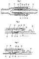
- Fig. 1 shows the coupling in functional position.
- the coupling incorporates a male part 10 and a female part 11.
- the nipple of the male part which is insertable into the female part, is provided with a circumferential locking groove 12.
- the female part is equipped with a slide-shaped, spring-loaded nonreturn valve 13, and it is enclosed by a sleeve 14, which is also spring-loaded. This is equipped with an internal, circumferential groove 15.
- the sleeve 14 guides at one hand at least one locking pawl 16, and on the other hand at least one locking member 17.
- the sleeve 14 When the male part is fully inserted in the female part, the sleeve 14 is retained by its spring in a position wherein the groove has been moved beyond locking pawl 16 and locking member 17, thus that these are retained in a secure engagement with the locking groove 12 of the male part.
- the locking member 17 is angular with an elongated web portion, which is insertable in a groove 18 in the female part and an edge-shaped pawl portion 19, which projects into the locking groove 12 of the male part and in functional position abuts the outer edge thereof.
- the sleeve 14 is moved backwards and thereby guarantees the engagement of the edge 19 of the locking member 17 with the locking groove 12, whereby the locking pawl 16 releases the grip about the nipple of the male part 10, which is urged outwards, and the nonreturn valve closes.
- the locking member 17 has followed the axial displacement outwards of the locking groove 12 with a secure engagement of the edge 19.
- the blowoff holes 20 now will be situated just in front of the groove 18 and the cross-formed groove 24 in the female part. Pressurized air remaining in the coupling and in the hose connected to the male part, then can be blown off without any disturbing sound.
- the locking member 16 is T-shaped in an elongated web portion 21 and a cross beam 22. This is thinner than the web portion, which adjacent the cross beam end is shaped to a transversal ridge 23.
- the outer edges of the cross beam is preferably curved corresponding to the contour of the female part.
- the sleeve 14 urges the cross beam 22 inwards, and urges then the edge 23, situated right inside, against the groove 12 in the male part. This efficiently ascertains retention and makes possible disconnection without large force.
- the locking pawl has been shaped as a two-armed lever, which has caused that the air pressure could exercise a hard pressure which has increased the resistance at disconnection, at the same time as the risk for deformation of the pawl has been present.
- the locking pawl 16 is insertable in a cross-shaped groove 24 in the female part.
- the groove has an elongated main part and a cross groove 25 corresponding to the crossbeam 22 in the locking pawl.
- the end of the locking pawl 16 facing away from the crossbeam 22 is angled with a part 26, which reaches into a circumferential groove 27 in the nonreturn valve.
- the angled part stabilizes the locking pawl, and the groove 27 has such an axial extent that the nonreturn valve can be closed without possibility for the locking pawl to be displaced.
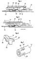
- Figs. 2-5 show the position of the locking pawl at different relative positions between male part and female part.
- Fig. 4 corresponds to the position in fig. 1, i.e. the locking position.
- the cross beam 22 has fallen into the cross groove 25, and the sleeve 14 has been pushed forward by means of its spring.
- the sleeve 14 is pulled backwards, such as shown in fig. 5.
- the annular groove 15 in the sleeve then will be positioned just above the cross beam 22 of the pawl and when the male part is pulled outwards, the inner sloping side wall in the locking groove 12 will press the cross beam in the groove 15 of the sleeve upwards, thus that the nipple will be completely free.
- Fig. 7 shows a partial change of the female part. This is equipped with two, diametrically opposed cross formed grooves 24 for the locking pawl, and straight grooves 18 for the locking body 17, displaced 90° relative to the first mentioned.
Landscapes
- Engineering & Computer Science (AREA)
- General Engineering & Computer Science (AREA)
- Mechanical Engineering (AREA)
- Quick-Acting Or Multi-Walled Pipe Joints (AREA)
Claims (5)
- Schlauchkupplung, umfassend ein Steckteil (10) mit einer Umfangsnut (12) und ein Muffenteil (11), wobei das Muffenteil mit einem Rückschlagventil (13) ausgerüstet ist, das beim Einsetzen des Steckteils betätigbar ist und das den Durchfluss durch die Kupplung steuert, wobei das Muffenteil von einer in axialer Richtung verschiebbaren Hülse (14) mit einer inneren Umfangsnut (15) umschlossen ist, die auf zumindest eine Sperrklinke (16), die das eingesetzte Steckteil zurückhält, und zumindest einen Sperrkörper (17) wirkt, der bei Trennung und teilweisem Zurückziehen des Steckteils stoßartig das Abblasen des Luftdruckes in der Kupplung erlaubt,
dadurch gekennzeichnet, dass die Sperrklinke (16) T-förmig und in eine entsprechend kreuzförmige Ausnehmung (24) in dem Steckteil (11) einsetzbar ist,
dass die Sperrklinke (16) einen Querbalken (23) aufweist,
dass der Stegabschnitt (21) der Sperrklinke am Ende des Querbalkens dicker gemacht und zu einem querverlaufenden Steg (22) geformt ist, der in Kupplungstellung mit der Umfangssperrnut (12) in dem Steckteil (10) zusammenwirkt, und dass bei einer Trennung, wenn die Sperrklinke (16) aus ihrem Eingriff mit dem Steckteil freigegeben ist, die geneigte Innenwand der Sperrnut (12) in der gleichen Art und Weise, was das Sperrelement (17) betrifft, den Querbalken (23) der Sperrklinke (16) nach außen in die Nut (15) in der zurückgezogenen Hülse (14) drückt, wodurch das Steckteil völlig freigegeben wird. - Schlauchkupplung nach Anspruch 1, dadurch gekennzeichnet, dass der Querbalken (23) der Sperrklinke (16) eine kleinere Dicke aufweist als der Stegabschnitt (21) der Sperrklinke.
- Schlauchkupplung nach Anspruch 2, dadurch gekennzeichnet, dass die obere Fläche des Querbalkens (22) im Bereich zu dem Muffenteil (11) gekrümmt ist.
- Schlauchkupplung nach Anspruch 2 oder 3, dadurch gekennzeichnet, dass das von dem Querbalken (23) weg weisende Ende (26) des Stegabschnittes (21) abgewinkelt ist und in montierter Stellung in eine Umfangsnut (27) im Rückschlagventil (13) hervorsteht.
- Schlauchkupplung nach einem der vorhergehenden Ansprüche, dadurch gekennzeichnet, dass das Muffenteil (11) mit zwei genau entgegengesetzten kreuzförmigen Ausnehmungen (24) für die Sperrklinke und zwei geradlinigen Ausnehmungen (24) für den Sperrkörper, die 90° relativ zu den zuerst erwähnten kreuzförmigen Ausnehmungen (24) versetzt sind, versehen ist.
Applications Claiming Priority (3)
| Application Number | Priority Date | Filing Date | Title |
|---|---|---|---|
| SE9602292 | 1996-06-11 | ||
| SE9602292A SE506301C2 (sv) | 1996-06-11 | 1996-06-11 | Snabbkoppling för hopkoppling av slangar |
| PCT/SE1997/001028 WO1997047911A1 (en) | 1996-06-11 | 1997-06-11 | Hose connection |
Publications (2)
| Publication Number | Publication Date |
|---|---|
| EP0902867A1 EP0902867A1 (de) | 1999-03-24 |
| EP0902867B1 true EP0902867B1 (de) | 2003-03-19 |
Family
ID=20402950
Family Applications (1)
| Application Number | Title | Priority Date | Filing Date |
|---|---|---|---|
| EP97927574A Expired - Lifetime EP0902867B1 (de) | 1996-06-11 | 1997-06-11 | Schlauchverbindung |
Country Status (6)
| Country | Link |
|---|---|
| EP (1) | EP0902867B1 (de) |
| AU (1) | AU3200897A (de) |
| DE (1) | DE69719981T2 (de) |
| ES (1) | ES2195146T3 (de) |
| SE (1) | SE506301C2 (de) |
| WO (1) | WO1997047911A1 (de) |
Families Citing this family (3)
| Publication number | Priority date | Publication date | Assignee | Title |
|---|---|---|---|---|
| CN1760563A (zh) * | 2004-10-12 | 2006-04-19 | 何建军 | 一种棘轮式超越离合器 |
| SE529075C2 (sv) | 2005-05-23 | 2007-04-24 | Bjoern Engdahl | Kombinerad spärr- och låskropp |
| ES2455592T3 (es) * | 2011-04-14 | 2014-04-16 | Cejn Ab | Acoplamiento para aire comprimido |
Family Cites Families (3)
| Publication number | Priority date | Publication date | Assignee | Title |
|---|---|---|---|---|
| US4060219A (en) * | 1975-06-04 | 1977-11-29 | Crawford Charles S | Quick disconnect coupler and safety check valve |
| FR2528148B1 (fr) * | 1982-06-08 | 1986-04-18 | Ind | Dispositif d'accouplement autoverrouillable |
| SE9203040L (sv) * | 1992-10-16 | 1994-04-11 | Bjoern Engdahl | Slangkoppling för tryckluft med don för tryckavlastning vid isärkoppling |
-
1996
- 1996-06-11 SE SE9602292A patent/SE506301C2/sv not_active IP Right Cessation
-
1997
- 1997-06-11 ES ES97927574T patent/ES2195146T3/es not_active Expired - Lifetime
- 1997-06-11 EP EP97927574A patent/EP0902867B1/de not_active Expired - Lifetime
- 1997-06-11 DE DE69719981T patent/DE69719981T2/de not_active Expired - Fee Related
- 1997-06-11 WO PCT/SE1997/001028 patent/WO1997047911A1/en not_active Ceased
- 1997-06-11 AU AU32008/97A patent/AU3200897A/en not_active Abandoned
Also Published As
| Publication number | Publication date |
|---|---|
| DE69719981D1 (de) | 2003-04-24 |
| SE9602292L (sv) | 1997-12-01 |
| ES2195146T3 (es) | 2003-12-01 |
| DE69719981T2 (de) | 2004-02-19 |
| EP0902867A1 (de) | 1999-03-24 |
| SE506301C2 (sv) | 1997-12-01 |
| SE9602292D0 (sv) | 1996-06-11 |
| WO1997047911A1 (en) | 1997-12-18 |
| AU3200897A (en) | 1998-01-07 |
Similar Documents
| Publication | Publication Date | Title |
|---|---|---|
| AU679951B2 (en) | Coupling for coupling together hoses or pipes for a pressure medium | |
| US6971684B2 (en) | Fast coupling for irrigation systems, particularly domestic irrigation systems | |
| US5547166A (en) | Hose coupling for compressed air | |
| US6039303A (en) | High pressure fluidline connector | |
| US5445358A (en) | Exhaust type quick action coupler | |
| US6581907B1 (en) | Pipe coupling | |
| JP3319712B2 (ja) | 管継手の雌部材 | |
| US5451031A (en) | Quick-connect-disconnect non-mar coupling | |
| US5752726A (en) | Quick-action coupling, in particular for refrigerant lines | |
| KR101891283B1 (ko) | 압축 공기 커플링 | |
| US4919334A (en) | Blow gun assembly | |
| EP0839298B1 (de) | Kupplungsstück für rohre | |
| US2708589A (en) | Tension actuated pipe coupling | |
| JPH02225898A (ja) | 加圧流体回路用自動結合器 | |
| KR20110004978U (ko) | 하이브리드 퀵 커플러 | |
| EP0902867B1 (de) | Schlauchverbindung | |
| US8267434B2 (en) | Hose coupling provided with non return valve and a combined locking and obstructing body | |
| EP1030993B1 (de) | Schnellkupplung | |
| KR100235820B1 (ko) | 관이음장치 및 관이음용 잠금장치 | |
| JPS605181Y2 (ja) | 管継手 | |
| JP3869150B2 (ja) | 管継手 | |
| JPS605182Y2 (ja) | 管継手 | |
| EP0635668B1 (de) | Verbindungsvorrichtung | |
| US12498068B2 (en) | Quick release connector with safety button | |
| JP4369564B2 (ja) | 管継手 |
Legal Events
| Date | Code | Title | Description |
|---|---|---|---|
| PUAI | Public reference made under article 153(3) epc to a published international application that has entered the european phase |
Free format text: ORIGINAL CODE: 0009012 |
|
| 17P | Request for examination filed |
Effective date: 19990111 |
|
| AK | Designated contracting states |
Kind code of ref document: A1 Designated state(s): DE ES FR GB IT |
|
| 17Q | First examination report despatched |
Effective date: 20010321 |
|
| GRAG | Despatch of communication of intention to grant |
Free format text: ORIGINAL CODE: EPIDOS AGRA |
|
| GRAG | Despatch of communication of intention to grant |
Free format text: ORIGINAL CODE: EPIDOS AGRA |
|
| GRAH | Despatch of communication of intention to grant a patent |
Free format text: ORIGINAL CODE: EPIDOS IGRA |
|
| GRAH | Despatch of communication of intention to grant a patent |
Free format text: ORIGINAL CODE: EPIDOS IGRA |
|
| GRAA | (expected) grant |
Free format text: ORIGINAL CODE: 0009210 |
|
| AK | Designated contracting states |
Designated state(s): DE ES FR GB IT |
|
| REG | Reference to a national code |
Ref country code: GB Ref legal event code: FG4D |
|
| REF | Corresponds to: |
Ref document number: 69719981 Country of ref document: DE Date of ref document: 20030424 Kind code of ref document: P |
|
| ET | Fr: translation filed | ||
| PLBE | No opposition filed within time limit |
Free format text: ORIGINAL CODE: 0009261 |
|
| STAA | Information on the status of an ep patent application or granted ep patent |
Free format text: STATUS: NO OPPOSITION FILED WITHIN TIME LIMIT |
|
| 26N | No opposition filed |
Effective date: 20031222 |
|
| PGFP | Annual fee paid to national office [announced via postgrant information from national office to epo] |
Ref country code: GB Payment date: 20050608 Year of fee payment: 9 |
|
| PGFP | Annual fee paid to national office [announced via postgrant information from national office to epo] |
Ref country code: FR Payment date: 20050620 Year of fee payment: 9 |
|
| PGFP | Annual fee paid to national office [announced via postgrant information from national office to epo] |
Ref country code: DE Payment date: 20050629 Year of fee payment: 9 |
|
| PGFP | Annual fee paid to national office [announced via postgrant information from national office to epo] |
Ref country code: ES Payment date: 20050630 Year of fee payment: 9 |
|
| PG25 | Lapsed in a contracting state [announced via postgrant information from national office to epo] |
Ref country code: GB Free format text: LAPSE BECAUSE OF NON-PAYMENT OF DUE FEES Effective date: 20060611 |
|
| PG25 | Lapsed in a contracting state [announced via postgrant information from national office to epo] |
Ref country code: ES Free format text: LAPSE BECAUSE OF NON-PAYMENT OF DUE FEES Effective date: 20060612 |
|
| PGFP | Annual fee paid to national office [announced via postgrant information from national office to epo] |
Ref country code: IT Payment date: 20060630 Year of fee payment: 10 |
|
| PG25 | Lapsed in a contracting state [announced via postgrant information from national office to epo] |
Ref country code: DE Free format text: LAPSE BECAUSE OF NON-PAYMENT OF DUE FEES Effective date: 20070103 |
|
| GBPC | Gb: european patent ceased through non-payment of renewal fee |
Effective date: 20060611 |
|
| REG | Reference to a national code |
Ref country code: FR Ref legal event code: ST Effective date: 20070228 |
|
| REG | Reference to a national code |
Ref country code: ES Ref legal event code: FD2A Effective date: 20060612 |
|
| PG25 | Lapsed in a contracting state [announced via postgrant information from national office to epo] |
Ref country code: FR Free format text: LAPSE BECAUSE OF NON-PAYMENT OF DUE FEES Effective date: 20060630 |
|
| PG25 | Lapsed in a contracting state [announced via postgrant information from national office to epo] |
Ref country code: IT Free format text: LAPSE BECAUSE OF NON-PAYMENT OF DUE FEES Effective date: 20070611 |