EP0902847B1 - Elektrochemische halbzelle mit druckkompensation - Google Patents
Elektrochemische halbzelle mit druckkompensation Download PDFInfo
- Publication number
- EP0902847B1 EP0902847B1 EP97924004A EP97924004A EP0902847B1 EP 0902847 B1 EP0902847 B1 EP 0902847B1 EP 97924004 A EP97924004 A EP 97924004A EP 97924004 A EP97924004 A EP 97924004A EP 0902847 B1 EP0902847 B1 EP 0902847B1
- Authority
- EP
- European Patent Office
- Prior art keywords
- gas
- electrolyte
- electrode
- half cell
- space
- Prior art date
- Legal status (The legal status is an assumption and is not a legal conclusion. Google has not performed a legal analysis and makes no representation as to the accuracy of the status listed.)
- Expired - Lifetime
Links
Images


Classifications
-
- C—CHEMISTRY; METALLURGY
- C25—ELECTROLYTIC OR ELECTROPHORETIC PROCESSES; APPARATUS THEREFOR
- C25B—ELECTROLYTIC OR ELECTROPHORETIC PROCESSES FOR THE PRODUCTION OF COMPOUNDS OR NON-METALS; APPARATUS THEREFOR
- C25B11/00—Electrodes; Manufacture thereof not otherwise provided for
- C25B11/02—Electrodes; Manufacture thereof not otherwise provided for characterised by shape or form
- C25B11/03—Electrodes; Manufacture thereof not otherwise provided for characterised by shape or form perforated or foraminous
- C25B11/031—Porous electrodes
- C25B11/032—Gas diffusion electrodes
-
- C—CHEMISTRY; METALLURGY
- C25—ELECTROLYTIC OR ELECTROPHORETIC PROCESSES; APPARATUS THEREFOR
- C25B—ELECTROLYTIC OR ELECTROPHORETIC PROCESSES FOR THE PRODUCTION OF COMPOUNDS OR NON-METALS; APPARATUS THEREFOR
- C25B15/00—Operating or servicing cells
- C25B15/08—Supplying or removing reactants or electrolytes; Regeneration of electrolytes
-
- C—CHEMISTRY; METALLURGY
- C25—ELECTROLYTIC OR ELECTROPHORETIC PROCESSES; APPARATUS THEREFOR
- C25B—ELECTROLYTIC OR ELECTROPHORETIC PROCESSES FOR THE PRODUCTION OF COMPOUNDS OR NON-METALS; APPARATUS THEREFOR
- C25B9/00—Cells or assemblies of cells; Constructional parts of cells; Assemblies of constructional parts, e.g. electrode-diaphragm assemblies; Process-related cell features
- C25B9/17—Cells comprising dimensionally-stable non-movable electrodes; Assemblies of constructional parts thereof
- C25B9/19—Cells comprising dimensionally-stable non-movable electrodes; Assemblies of constructional parts thereof with diaphragms
-
- H—ELECTRICITY
- H01—ELECTRIC ELEMENTS
- H01M—PROCESSES OR MEANS, e.g. BATTERIES, FOR THE DIRECT CONVERSION OF CHEMICAL ENERGY INTO ELECTRICAL ENERGY
- H01M4/00—Electrodes
- H01M4/86—Inert electrodes with catalytic activity, e.g. for fuel cells
- H01M4/8605—Porous electrodes
- H01M4/8626—Porous electrodes characterised by the form
-
- H—ELECTRICITY
- H01—ELECTRIC ELEMENTS
- H01M—PROCESSES OR MEANS, e.g. BATTERIES, FOR THE DIRECT CONVERSION OF CHEMICAL ENERGY INTO ELECTRICAL ENERGY
- H01M8/00—Fuel cells; Manufacture thereof
- H01M8/08—Fuel cells with aqueous electrolytes
-
- Y—GENERAL TAGGING OF NEW TECHNOLOGICAL DEVELOPMENTS; GENERAL TAGGING OF CROSS-SECTIONAL TECHNOLOGIES SPANNING OVER SEVERAL SECTIONS OF THE IPC; TECHNICAL SUBJECTS COVERED BY FORMER USPC CROSS-REFERENCE ART COLLECTIONS [XRACs] AND DIGESTS
- Y02—TECHNOLOGIES OR APPLICATIONS FOR MITIGATION OR ADAPTATION AGAINST CLIMATE CHANGE
- Y02E—REDUCTION OF GREENHOUSE GAS [GHG] EMISSIONS, RELATED TO ENERGY GENERATION, TRANSMISSION OR DISTRIBUTION
- Y02E60/00—Enabling technologies; Technologies with a potential or indirect contribution to GHG emissions mitigation
- Y02E60/30—Hydrogen technology
- Y02E60/50—Fuel cells
Definitions
- the invention relates to an electrochemical half cell consisting at least of an electrode space for receiving an electrolyte, a gas space and at least one gas diffusion electrode separating the gas space and the electrode space as an anode or cathode, in which the gas space is divided into two or more Gas pockets is divided in which a gas supply or gas discharge via separate openings and the pressure on the electrolyte side of the electrode against the pressure on the gas side of the electrode through an opening in the Gas pockets to the electrolyte is compensated.
- the gas diffusion electrode is an open-pore membrane between the electrolyte and Gas space, which has an electrically conductive layer with catalyst, and it should allow an electrochemical reaction, e.g. Reduction of oxygen, at the three-phase boundary of the electrolyte, catalyst and reactant gas in the membrane to operate.
- the boundary layer is generally determined by the surface tension of the electrolyte on the hydrophobic electrode material against the hydrostatic pressure of the electrolyte on the membrane in the membrane held. However, there is only a slight pressure drop between the gas side and Liquid side of the membrane permitted. If the gas pressure is too high, it breaks finally the gas passes through the membrane and the electrode is in this Function is disturbed and the electrolysis process is interrupted.
- DE-A-4 444 114 describes an electrochemical half cell with a gas diffusion electrode, in which a pressure compensation between the gas space and the Electrolyte space reached on both sides of a gas diffusion electrode is that the gas space in two or more cascading one above the other Gas pockets is divided, which are separated from each other and to the electrolyte are open at the bottom, so that the pressure in each gas pocket is open via the opening Electrolytes in equilibrium with the pressure of the liquid column of the electrolyte in the corresponding part of the electrode space located in front of the gas diffusion electrode stands, and where a possible gas supply or gas removal via the There are openings to the electrolyte.
- the gas bubbles burst at the meniscus of the electrolyte in the respective gas pocket also has the consequence that an undesirable in the gas space Spray of electrolyte droplets forms on the diffusion electrode precipitates and affects the function of the diffusion electrode.
- the further object of the invention from the prior art is to to develop an electrochemical half cell that takes advantage of simple Has pressure compensation, but at the same time the disadvantages of the known Does not have cells and in particular active ventilation of the gas space behind the diffusion electrode enables.
- an electrochemical half cell which is the subject of the invention, consisting at least of an electrode space for receiving an electrolyte, a gas space and at least one gas space and gas diffusion electrode separating the electrode space as anode or cathode, in which the gas space is divided into two or more gas pockets one above the other which are separated from each other and each have an opening to the electrolyte have so that the pressure in each gas pocket through the opening to Electrolytes in equilibrium with the pressure of the liquid column of the electrolyte in the corresponding part of the electrode space located in front of the gas diffusion electrode stands, characterized in that the gas supply and the gas discharge the individual gas pocket are spatially separated.
- the gas supply and gas discharge are in a gas pocket attached laterally offset from each other, so that a lateral flow of the electrode gas results in the gas pocket.
- the gas exchange in the respective gas pocket improved and the accumulation of unwanted foreign gases, e.g. occurs in the known cell arrangement avoided.
- the isothermal direct contact of the electrode gas with the electrolyte ensured that the gas on the gas side of the diffusion electrode is always saturated and humid and therefore a "crystallization" of Electrolyte solids, especially in the membrane structure of the diffusion electrode is avoided.
- the gas pockets are closed on all sides Chambers formed, one boundary wall of the gas diffusion electrode and the gas supply with electrode gas at one side exhibit.
- the excess electrode gas by immersion in the pressure compensating, stagnant electrolyte fluid.
- the side forced ventilation the half cell with electrode gas achieved in that gas supply and Gas discharge from one gas pocket to the next higher gas pocket are arranged alternately so that the gas discharge of a gas pocket under the Gas supply of the next higher gas pocket is arranged.
- the gas pockets can have gas collecting aprons on the back wall of the Gas bag are attached.
- a baffle is used Collect the gas bubble rising from a lower gas pocket outlet vertically on the back wall of the gas bag and laterally projects beyond the outlet of the gas pocket discharge underneath.
- a bladder channel is used as the gas supply for the gas pockets, which is down protrudes openly into the electrolyte.
- the bladder channel is e.g. above the outlet of the Gas discharge arranged a lower gas pocket, so that escaping electrode gas bubbled into the bladder canal.
- the bladder canal can be at its lower end have a laterally widened bubble catcher.
- the lower outlet is designed as a U-tube, the one leg extends a little bit open into the opening of the bladder channel.
- the variants mentioned allow the electrode gas to be transferred from Gas pocket to gas pocket so that the meniscus of the electrolyte fluid incoming gas bubbles of the electrode gas still in an area outside burst the actual gas bag. This will cause splashing on the back avoided the diffusion electrode with electrolyte. This will be especially so reached when the bladder channel or the gas collecting apron is offset laterally is, e.g. towards the middle of the half cell, opposite the opening to the chamber of the Gas bag. In this case it will be in the bladder channel or gas collecting apron collected gas is piped to the side of the opening.
- the inlet of the gas supply to each gas pocket can be designed differently his. In addition to the use of a simple opening, several superimposed ones can also be used Openings or one or more, maximum over the amount of Gas pocket extended inlet slots may be provided to e.g. the back of the electrode to supply fresh electrode gas over its entire height.
- the openings can be blocked with metal sheets opposite the electrode wall, which may be covered with Electrolyte entrained in the gas stream and run back if necessary can.
- Another variant of the half-cell according to the invention with pressure compensation has a continuous one instead of one from the gas pocket Electrode gas routing a single feeding of the individual one above the other Gas pockets through gas supply lines, which may have their own Control or shut-off valves are equipped.
- the pressure compensation of the individual gas pockets takes place via the Gas discharge of the gas pockets openly immersed in the electrolyte.
- Electrode reaction harmful gases e.g. gases that inhibit the electrode reaction
- a meandering gas flow from the lowest gas pocket can enrich up to the top gas pocket.
- This arrangement also makes it possible to "switch off” a portion of the Gas diffusion electrode surface by flushing the selected gas pocket with a Inert gas (e.g. an inert gas). This means that during operation of the half cell Control of the individual power of the "switched off” electrode surface possible.
- a Inert gas e.g. an inert gas
- Half-cell hydraulically the electrode space and the rear electrolyte space can the respective differential pressure, which is the same for all chambers, by different levels or drainage heights in both rooms become.
- a controllable overpressure can be set, which is then for all gas pockets is the same height as the electrode space.
- the electrolyte drain from the cell is preferred via a standpipe led out below or possibly to a side wall of the cell, it is directly possible to derive electrolyte and excess gas together by the electrolyte from the electrode compartment is only on the top Gas pocket electrode flows into the rear electrolyte space, from where it via the standpipe together with the excess oxygen from the cell emerges downwards or, in the case of a side drain, also to the side.
- Different Heights of the standpipe lead to different differential pressures, whereby this time the liquid pressure is higher than the gas pressure, which is especially for a full-surface contact of cloth-like gas diffusion electrodes on the power distribution grid is an advantage. If necessary, it can then on holding and clamping devices for the electrode.
- Removal of electrolyte and excess gas via the standpipe can also do this a discharge pipe attached to the side of the half cell, the separation of gas and electrolyte, e.g. in a collector next to the cell. And up in this way the liquid pressure can be higher than the gas pressure across the gas diffusion electrode can be set.
- the half cell according to the invention can be provided by a corresponding number of gas pockets can be expanded to any technically meaningful sizes. Because the needed Quantity of gas (e.g. oxygen) for representative electrolysis loads, for example 0.7 to 1 standard cubic meter per square meter of cathode area and hour by suitable size of the bubble openings the necessary gas transport without problems to accomplish, as hydraulic tests have shown.
- gas e.g. oxygen
- the holder and the electrical contact of the gas diffusion electrode, in particular in half-cells of membrane electrolysers is basically known. At The use of several electrode segments as the gas diffusion electrode takes place Holding the gas diffusion electrode segments gas-tight with each other and opposite the electrode room.
- the holding elements for the gas diffusion electrode can e.g. as terminal strips or suitably encased magnetic strips that are initially designed as Serve assembly aid.
- the holding elements can in the case of electrolytic cells with intermediate Ion exchange membrane after assembly over the ion exchange membrane support on the counter electrode structure behind it and thus ensure a corresponding pressure on the gas diffusion electrode, which is also contacted electrically.
- the holding elements can be attached to the ion exchange membrane facing side, notches in the direction of flow identify that a homogeneous even in the tensioned state of the electrolysis cell Allow electrolyte to pass from department to department of the electrode compartment.
- an elastic spacer fills the Invention from the narrow electrode space, which not only functions as a spacer and turbulence generator for the electrolyte flow met, but also can be placed over the holding elements mentioned, clamped together with these and thereby another elastic component for the pressure and sealing the gas diffusion electrode.
- the spacing between the gas diffusion electrode and membrane guaranteed by covered wires that are vertical through the individual departments and into the notches of the Holding elements are clamped.
- the gas diffusion electrode segments can also be held with the aid of a Retaining strip made with T-profile, the long leg in suitable sections runs out in tabs which are inserted through the holding structure in such a way that a rearward tightening, e.g. via clamping wedges, which are attached by suitable Drilled holes can be done.
- a Retaining strip made with T-profile
- the long leg in suitable sections runs out in tabs which are inserted through the holding structure in such a way that a rearward tightening, e.g. via clamping wedges, which are attached by suitable Drilled holes can be done.
- a rearward tightening e.g. via clamping wedges, which are attached by suitable Drilled holes
- the power supply to the gas diffusion electrode can be known in principle Orders are made.
- the gas diffusion electrode rests on the gas side, gas side or electrolysis side, and the ensures short current paths.
- a gas diffusion electrode with Integrated metallic grille can optionally on the separate metallic lattice structure on the holding device can be dispensed with if another simple abutment supports the diffusion electrode in Direction of the gas space is guaranteed.
- the power supply can also preferably via a low-resistance connection to the Back of the half cell.
- the usual ones can in principle be used commercially available membrane electrolysers for the electrolysis of alkali halide solution, if they have a sufficiently deep cathode chamber, on the energy-saving Operation with e.g. Change oxygen consumption cathodes.
- gas diffusion electrodes e.g. Guys with integrated metallic support or power distribution grids or on carbon tiles or other conductive structures constructed electrodes.
- An electrochemical half cell connected as an oxygen consumption cathode has following basic structure (see Figure 2).
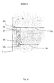
- Half cell 1 is from another half cell (not shown) by one Membrane 13 separated.
- Electrolyte 100 (here aqueous NaOH) is fed through a supply line 9 fed to the electrode space 20 and flows between the membrane 13 and a gas diffusion electrode 14 through the electrolyte gap 15 to Collection chamber 5.
- the electrode 14 has a low-resistance, not shown electrical contact to the outside with an external power source connected.
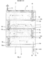
- the gas space 2 behind the diffusion electrode 14 is in gas pockets one above the other 2a, 2b, 2c, 2d divided.
- the rear space 3 behind the gas pockets 2a - 2d contains electrolyte 100 which, via the collecting chamber 5, contains the electrolyte 100 in Electrolyte gap 15 is in pressure equilibrium.
- the excess gas becomes via a dip tube 12a into a bladder channel 3a, as in FIG. 1 shown.
- the bladder channel 3a is open at the bottom and is in connection with the pressure-compensating electrolyte 100 of the rear area 3. Laterally and above is the bladder channel 3a except for an opening 7 in the next higher gas pocket 2b closed.
- the back of the bladder channel 3a is either through the Rear wall of the electrochemical half cell 1 (see FIG. 2: section BB ') or but formed by an independent end wall (not shown). Latter Construction enables e.g. the independent assembly and disassembly of the gas bag insert.
- the rising bubbles separate from the electrolyte in the upper area of the bladder canal 3a at the level of the meniscus, which extends through the End of the dip tube 12b for removing the excess gas on the other side the next higher gas pocket 2b taking into account the bubble effects in the Bladder channel 3a sets.
- the active flow through the electrolyte gap 15 between membrane 13 and gas diffusion electrode 14 is through a partition plate 18th between the back space 3 and the electrolyte distribution chamber 20, while in the upper collecting chamber 5 electrolyte gap 15 and back space 3 for pressure equalization are interconnected.
- the bladder channels 3a-3d have no direct opening into the respective gas pocket 2a, 2b, 2c, 2d, but a side connection 21 in upper area of the collecting gas bubbles in the only open at the bottom Area 22 next to the bladder canal 3a - 3d.
- the area 22 becomes Calmed gas freed from the spray of bursting gas bubbles via a bore 23 directed into the next gas pocket 2b - 2d, as shown in Figure 4.
- the horizontal position of the bladder channels 3a - 3d is arbitrary and necessary here only according to the structural framework of the respective electrochemical To judge half cell.
- the electrode gas is passed on in a cascade Similar assemblies from lower gas pockets 2a-2c to the next higher ones Gas pockets 2b - 2d until the unused electrode gas is removed, e.g. is discharged together with the electrolyte through a tube 11.
- This variant is particularly suitable for electrolysers with vertical lines Structures.
- Another alternative of pressure compensation is characterized by the following elements: after exposure to the The bottom gas pocket 2a leaves the excess gas through an opening 30a otherwise closed gas pocket 2a, corresponding to FIG. 5, and collects itself in the side apron 31a, which in turn is separate on the back is closed, or gas-tight with the rear wall of the electrochemical half cell completes. Via the bottom open, with the pressure compensating liquid in Connected side skirt 31a bubbles up the excess electrode gas the side apron 32a, which is constructed analogously to the apron 31a. The Side skirt 32a is extended laterally to the extent that the gas pocket 31a rising gas bubbles can be caught safely. The electrode gas collects here and enters the next higher gas pocket 2b via the opening 30b.
- the bladder channels 40a-40d are open at the bottom and directly in contact with the pressure compensating liquid (electrolyte 100) stand.
- the bladder channels are supplied via the distributor pipe 44 feeds into the respective bladder channel 40a-40d via one nozzle 45 each.
- the Conditions on the respective nozzle 45 are isobar because of the direct connection with the pressure compensating liquid, resulting in an even Feed into the respective bladder channels.
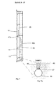
- these are with diving bell-like Caps 46 covered (see detail A on section A-A 'in Figure 7a).
- the controlled one Bubbles are released via slots 47 at the lower end of the caps 46 Electrode gas flows through the gas pocket and leaves the pocket, for example Pocket 2c, at the opposite end via the dip tube 42c, as at the cut B - B 'shown in Figure 8 together with the pressure compensation. For one free rise of the bubbles and the necessary pressure compensation in turn ensure the openings 19 in the rear structural elements 6a-6e.
- FIG. 9 Another variant of the half cell according to the invention is shown in FIG. 9:
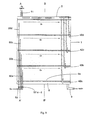
- the individual gas pockets 2a - 2d are fed via direct insertion tubes 50a, 50b, 50c, 50d.
- the individual pipes 50a - 50d according to the pressure conditions in the associated gas pockets e.g. about Throttles 52a-52d are throttled relative to the feed pipe 51.
- the adaptation can, however, be done once or permanently installed.
- the rear structural elements are 6a-6e perforated to allow free removal of the gas bubbles and pressure equalization to ensure.
- the last variant in particular enables a particularly flat half-cell construction.
Landscapes
- Chemical & Material Sciences (AREA)
- Chemical Kinetics & Catalysis (AREA)
- Electrochemistry (AREA)
- Engineering & Computer Science (AREA)
- Materials Engineering (AREA)
- Metallurgy (AREA)
- Organic Chemistry (AREA)
- General Chemical & Material Sciences (AREA)
- Manufacturing & Machinery (AREA)
- Sustainable Development (AREA)
- Sustainable Energy (AREA)
- Life Sciences & Earth Sciences (AREA)
- Electrolytic Production Of Non-Metals, Compounds, Apparatuses Therefor (AREA)
- Hybrid Cells (AREA)
- Fuel Cell (AREA)
- Primary Cells (AREA)
- Secondary Cells (AREA)
Description
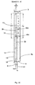
- Figur 1
- Eine Variante der erfindungsgemäßen Halbzelle, mit Blasenkanälen ausgeführt als Sauerstoffverzehrkathode, gezeichnet im Querschnitt parallel zur Diffusionselektrodenfläche.
- Figur 2
- Einen Querschnitt durch die Halbzelle nach Figur 1 entsprechend der Linie B-B' in Figur 1.
- Figur 3
- Einen Querschnitt durch die Halbzelle nach Figur 1 entsprechend der Linie C-C' in Figur 1.
- Figur 4
- Das Detail einer Variante der erfindungsgemäßen Halbzelle nach Fig. 1 mit besonderer Gaszufuhr.
- Figur 5
- Eine erfindungsgemäße Halbzelle mit seitlicher Ausdehnung der Gassammelschürzen im Querschnitt.
- Figur 6
- Ein Beispiel der erfindungsgemäßen Halbzelle mit direkter Gaszuführung der einzelnen Gastaschen im Querschnitt.
- Figur 7
- Einen Schnitt entsprechend der Linie A-A' in Figur 6 durch die Halbzelle gemäß Figur 6.
- Figur 7a
- Ein vergrößertes Detail von Figur 7.
- Figur 8
- Einen Schnitt entsprechend der Linie B-B' in Figur 6 durch die Halbzelle gemäß Figur 6.
- Figur 9
- Eine Variante der Halbzelle nach Figur 6 mit Gaszuführung der Gastaschen über Einsteckrohre im Querschnitt.
- Figur 10
- Einen Schnitt entsprechend der Linie A-A' in Figur 9 durch die Halbzelle gemäß Figur 9.
Claims (15)
- Elektrochemische Halbzelle (1), bestehend wenigstens aus einem Elektrodenraum (3, 15) zur Aufnahme eines Elektrolyten (100), einem Gasraum (2) und mindestens einer Gasraum (2) und Elektrodenraum (3, 15) trennenden Gasdiffusionselektrode (14) als Anode oder Kathode, in der der Gasraum (2) in zwei oder mehrere übereinanderliegende Gastaschen (2a, 2b, 2c, 2d) aufgeteilt ist, die voneinander getrennt sind und eine Öffnung (7) zum Elektrolyten (100) hin aufweisen, so daß der Druck in jeder Gastasche (2a, 2b, 2c, 2d) über eine Öffnung (7) zum Elektrolyten (100) im Gleichgewicht zum Druck der Flüssigkeitssäule des Elektrolyten (100) im entsprechenden Teil (15) des vor der Gasdiffusionselektrode (14) liegenden Elektrodenraums (3, 15) steht, dadurch gekennzeichnet, daß die Gaszuführung (7) und die Gasabführung (12a, 12b, 12c, 12d) der einzelnen Gastaschen (2a, 2b, 2c, 2d) räumlich voneinander getrennt sind.
- Halbzelle gemäß Anspruch 1, dadurch gekennzeichnet, daß die Gaszuführung (7) und die Gasabführung (12a, 12b, 12c, 12d) in der einzelnen Gastasche (2a, 2b, 2c, 2d) seitlich voneinander versetzt angeordnet sind, so daß eine seitliche Strömung des Elektrodengases in der Gastasche (2a, 2b, 2c, 2d) resultiert.
- Halbzelle gemäß den Ansprüchen 1 bis 2, dadurch gekennzeichnet, daß die übereinanderliegenden Gastaschen 2a, 2b, 2c, 2d) durch eine Verbindung von Gasabführung (12a, 12b, 12c, 12d) einer unteren Gastasche (2a, 2b, 2c) zur Gaszuführung (3a, 3b, 3c, 3d) einer darüber liegenden Gastasche (2b, 2c, 2d) kaskadenartig miteinander verbunden sind.
- Halbzelle gemäß den Ansprüchen 1 bis 2, dadurch gekennzeichnet, daß die Gastaschen (2a, 2b, 2c, 2d) je eine direkte Gaszuführung aufweisen.
- Halbzelle gemäß den Ansprüchen 1 bis 4, dadurch gekennzeichnet, daß die Gastaschen (2a, 2b, 2c, 2d) eine Tauchung (42a, 42b, 42c, 42d) zur Ableitung des Überschußgases aus der Gastasche (2a, 2b, 2c, 2d) aufweisen.
- Halbzelle gemäß den Ansprüchen 1 bis 5, dadurch gekennzeichnet, daß die Gastaschen (2a, 2b, 2c, 2d) Blasenkanäle (3a, 3b, 3c, 3d) zur Aufnahme von zuströmendem Elektrodengas aufweisen, die mit der Öffnung (7) direkt oder indirekt verbunden sind.
- Halbzelle gemäß den Ansprüchen 1 bis 6, dadurch gekennzeichnet, daß die Gastaschen (2a, 2b, 2c, 2d) seitliche Gassammelschürzen (32a, 32b, 32c, 32d) als Gaszuführungen und/oder seitliche Schürzen (31a, 31b, 31c, 31d) als Gasabführungen aufweisen.
- Halbzelle gemäß den Ansprüchen 1 bis 7, dadurch gekennzeichnet, daß die Gastaschen (2a, 2b, 2c, 2d) zum Elektrolyten (100) offene Blasenkanäle (40a, 40b, 40c, 40d) für eine direkte unabhängige Gaszufuhr aufweisen.
- Halbzelle gemäß Anspruch 8, dadurch gekennzeichnet, daß die Gaszufuhr der Blasenkanäle (40a, 40b, 40c, 40d) über angedrosselte Düsen (45) erfolgt, die gegebenenfalls mit seitlich geschlitzten Tauchglocken (46) abgedeckt sind.
- Halbzelle gemäß Anspruch 4, dadurch gekennzeichnet, daß die Gastaschen (2a, 2b, 2c, 2d) Einsteckrohre (50a, 50b, 50c, 50d) für die direkte Gaszufuhr aufweisen, die gegebenenfalls zusätzlich jeweils mit Regelventilen (52a, 52b, 52c, 52d) zur Regelung des Gasstromes in die Gastaschen (2a, 2b, 2c, 2d) versehen sind.
- Halbzelle gemäß den Ansprüchen 1 bis 10, dadurch gekennzeichnet, daß die Gaszuführung (7) und die Gasabführungen (12a, 12b, 12c, 12d) übereinanderliegender Gastaschen (2a, 2b, 2c, 2d) auf wechselnden Seiten oder auf der jeweils gleichen Seite liegen.
- Halbzelle nach den Ansprüchen 1-11, dadurch gekennzeichnet, daß durch hydraulische Trennung von Elektrolytspalt (15) und Elektrolytrückraum (3) der Differenzdruck zwischen den Bereichen vor und hinter der Gasdiffusionselektrode (14) frei eingestellt werden kann.
- Halbzelle nach den Ansprüchen 1 bis 12, dadurch gekennzeichnet, daß die Gaszuführung (10) in die unterste Gastasche (2a) koaxial über einen Stutzen (10) gemeinsam mit der Elektrolytzuführung (9) in den Elektrodenraum (3, 15) erfolgt und/oder die Ableitung des Überschußgases zusammen mit dem Elektrolyten nach oben durch einen Ablaufstutzen (11) erfolgt.
- Halbzelle nach den Ansprüchen 1 bis 13, dadurch gekennzeichnet, daß der Elektrolyspalt (15) oben mit dem Elektrolytrückraum (3) hinter den Gastaschen (2a, 2b, 2c, 2d) hydraulisch verbunden ist, wodurch Elektrolyt in den Elektrolytrückraum (3) überströmt und die Ableitung des Überschußgases gemeinsam mit dem Elektrolyten (22) über ein Standrohr im Bereich hinter den Gastaschen (2a, 2b, 2c, 2d) nach unten oder über einen seitlich angebrachten Stutzen mit auf gleicher Höhe liegendem Gas-Flüssigkeitstrenner zur Seite erfolgt.
- Halbzelle nach Anspruch 14, dadurch gekennzeichnet, daß über die Höhe des Standrohres im Elektrolytrückraum (3) hinter den Gastaschen (2a, 2b, 2c, 2d) bzw. über die Höhenlage des seitlich angebrachten Stutzens der Flüssigkeitspegel des Elektrolyten (100) gegenüber dem Pegel des Elektrolyten (100) im Elektrolytspalt (15) unterschiedlich eingestellt werden und damit für alle Gastaschen (2a, 2b, 2c, 2d) der Differenzdruck zwischen Gasraum (2) und Elektrolytspalt (15) gleichermaßen variiert werden kann.
Applications Claiming Priority (3)
| Application Number | Priority Date | Filing Date | Title |
|---|---|---|---|
| DE19622744A DE19622744C1 (de) | 1996-06-07 | 1996-06-07 | Elektrochemische Halbzelle mit Druckkompensation |
| DE19622744 | 1996-06-07 | ||
| PCT/EP1997/002689 WO1997047787A1 (de) | 1996-06-07 | 1997-05-26 | Elektrochemische halbzelle mit druckkompensation |
Publications (2)
| Publication Number | Publication Date |
|---|---|
| EP0902847A1 EP0902847A1 (de) | 1999-03-24 |
| EP0902847B1 true EP0902847B1 (de) | 2000-04-12 |
Family
ID=7796315
Family Applications (1)
| Application Number | Title | Priority Date | Filing Date |
|---|---|---|---|
| EP97924004A Expired - Lifetime EP0902847B1 (de) | 1996-06-07 | 1997-05-26 | Elektrochemische halbzelle mit druckkompensation |
Country Status (17)
| Country | Link |
|---|---|
| US (1) | US6165332A (de) |
| EP (1) | EP0902847B1 (de) |
| JP (1) | JP3271987B2 (de) |
| KR (1) | KR100402869B1 (de) |
| CN (1) | CN1084802C (de) |
| AT (1) | ATE191755T1 (de) |
| AU (1) | AU712543B2 (de) |
| BR (1) | BR9709657A (de) |
| CA (1) | CA2257315A1 (de) |
| DE (2) | DE19622744C1 (de) |
| ES (1) | ES2146999T3 (de) |
| ID (1) | ID17123A (de) |
| MY (1) | MY132669A (de) |
| NO (1) | NO985523D0 (de) |
| TW (1) | TW360991B (de) |
| WO (1) | WO1997047787A1 (de) |
| ZA (1) | ZA975009B (de) |
Families Citing this family (24)
| Publication number | Priority date | Publication date | Assignee | Title |
|---|---|---|---|---|
| US5229588A (en) | 1991-09-30 | 1993-07-20 | Ncr Corporation | Dual aperture optical scanner |
| DE19646950A1 (de) | 1996-11-13 | 1998-05-14 | Bayer Ag | Elektrochemische Gasdiffusionshalbzelle |
| DE19852363C1 (de) * | 1998-11-13 | 2000-05-18 | Mtu Friedrichshafen Gmbh | Brennstoffzellenanordnung |
| EP1092789B1 (de) * | 1999-03-31 | 2011-08-10 | Toagosei Co., Ltd. | Elektrolytische zelle mit gasdiffusionselektrode und stromverteilungsverfahren für elektrolytische zelle |
| DE19954247C2 (de) * | 1999-11-11 | 2002-11-14 | Wolfgang Strewe | Elektrolysezelle mit Gasdiffusionselektrode für großtechnische Anlagen sowie Verwendungen der Elektrolysezelle |
| DE19959079A1 (de) | 1999-12-01 | 2001-06-07 | Bayer Ag | Elektrochemische Zelle für Elektrolyseure mit Einzelelementtechnik |
| ITMI20010362A1 (it) * | 2001-02-23 | 2002-08-23 | Nora Tecnologie Elettrochimich | Cella di elettrolisi con elettrodo a diffusione di gas operante a pressione controllata |
| DE10152276A1 (de) * | 2001-10-23 | 2003-04-30 | Bayer Ag | Elektrolysezellen-Halbelement zum Betrieb von Gasdiffusionselektroden mit Trennung der Funktionsräume |
| WO2003035936A2 (de) * | 2001-10-23 | 2003-05-01 | Bayer Materialscience Ag | Elektrochemische halbzelle |
| DE10152791A1 (de) * | 2001-10-25 | 2003-05-08 | Bayer Ag | Verfahren zur Herstellung von Chlor und Natronlauge durch Elektrolyse mittels Gasdiffusionselektroden-Demister |
| DE102005003527A1 (de) * | 2005-01-25 | 2006-07-27 | Uhdenora S.P.A. | Elektrolysezelle mit erweiterter aktiver Membranfläche |
| JP4834329B2 (ja) * | 2005-05-17 | 2011-12-14 | クロリンエンジニアズ株式会社 | イオン交換膜型電解槽 |
| WO2008080118A1 (en) | 2006-12-23 | 2008-07-03 | Miox Corporation | Internal flow control in electrolytic cells |
| DE102010024053A1 (de) | 2010-06-16 | 2011-12-22 | Bayer Materialscience Ag | Sauerstoffverzehrelektrode und Verfahren zu ihrer Herstellung |
| DE102010039846A1 (de) | 2010-08-26 | 2012-03-01 | Bayer Materialscience Aktiengesellschaft | Sauerstoffverzehrelektrode und Verfahren zu ihrer Herstellung |
| DE102010062421A1 (de) | 2010-12-03 | 2012-06-06 | Bayer Materialscience Aktiengesellschaft | Sauerstoffverzehrelektrode und Verfahren zu ihrer Herstellung |
| DE102011005133A1 (de) | 2011-03-04 | 2012-09-06 | Bayer Materialscience Aktiengesellschaft | Verfahren zum Betrieb einer Sauerstoffverzehrelektrode |
| AU2012382382A1 (en) | 2012-06-12 | 2015-01-15 | Aquahydrex Pty Ltd | Breathable electrode and method for use in water splitting |
| KR20160040614A (ko) | 2013-07-31 | 2016-04-14 | 아쿠아하이드렉스 프로프라이어터리 리미티드 | 기체 확산 전극(들)을 가지는 전기-합성 또는 전기-에너지 전지 |
| WO2015082319A1 (de) | 2013-12-04 | 2015-06-11 | Evonik Industries Ag | Vorrichtung und verfahren zum flexiblen einsatz von strom |
| DE102017217361A1 (de) | 2017-09-29 | 2019-04-04 | Thyssenkrupp Uhde Chlorine Engineers Gmbh | Elektrolysevorrichtung |
| PL3543375T3 (pl) * | 2018-03-22 | 2022-01-24 | Hymeth Aps | Wysokociśnieniowy system elektrolizera zawierający system kompensacji ciśnienia |
| CA3127358A1 (en) | 2019-02-01 | 2020-08-06 | Aquahydrex, Inc. | Electrochemical system with confined electrolyte |
| CN112729456B (zh) * | 2020-12-16 | 2023-05-02 | 湖北亿纬动力有限公司 | 软包电芯气囊袋设计方法 |
Family Cites Families (5)
| Publication number | Priority date | Publication date | Assignee | Title |
|---|---|---|---|---|
| US4657651A (en) * | 1986-04-04 | 1987-04-14 | The Dow Chemical Company | Vertical gas electrode operation |
| DE4120679C2 (de) * | 1991-06-22 | 1995-11-09 | Grimma Masch Anlagen Gmbh | Elektrolyseverfahren und Elektrolysezelle für gasentwickelnde oder gasverbrauchende elektrolytische Prozesse |
| JPH07220728A (ja) * | 1994-02-07 | 1995-08-18 | Tanaka Kikinzoku Kogyo Kk | 気泡捕集型ガス電極 |
| DE4444114C2 (de) * | 1994-12-12 | 1997-01-23 | Bayer Ag | Elektrochemische Halbzelle mit Druckkompensation |
| JPH0920728A (ja) * | 1995-07-10 | 1997-01-21 | Tokuyama Corp | カーボネート化合物及びその製造方法 |
-
1996
- 1996-06-07 DE DE19622744A patent/DE19622744C1/de not_active Expired - Fee Related
-
1997
- 1997-05-26 EP EP97924004A patent/EP0902847B1/de not_active Expired - Lifetime
- 1997-05-26 AT AT97924004T patent/ATE191755T1/de not_active IP Right Cessation
- 1997-05-26 CN CN97195317A patent/CN1084802C/zh not_active Expired - Fee Related
- 1997-05-26 BR BR9709657A patent/BR9709657A/pt not_active IP Right Cessation
- 1997-05-26 KR KR10-1998-0709972A patent/KR100402869B1/ko not_active Expired - Fee Related
- 1997-05-26 WO PCT/EP1997/002689 patent/WO1997047787A1/de not_active Ceased
- 1997-05-26 DE DE59701442T patent/DE59701442D1/de not_active Expired - Lifetime
- 1997-05-26 ES ES97924004T patent/ES2146999T3/es not_active Expired - Lifetime
- 1997-05-26 AU AU29609/97A patent/AU712543B2/en not_active Ceased
- 1997-05-26 CA CA002257315A patent/CA2257315A1/en not_active Abandoned
- 1997-05-26 US US09/194,787 patent/US6165332A/en not_active Expired - Fee Related
- 1997-05-26 JP JP50111798A patent/JP3271987B2/ja not_active Expired - Fee Related
- 1997-06-05 TW TW086107721A patent/TW360991B/zh active
- 1997-06-06 MY MYPI97002542A patent/MY132669A/en unknown
- 1997-06-06 ZA ZA9705009A patent/ZA975009B/xx unknown
- 1997-06-09 ID IDP971962A patent/ID17123A/id unknown
-
1998
- 1998-11-26 NO NO985523A patent/NO985523D0/no not_active Application Discontinuation
Also Published As
| Publication number | Publication date |
|---|---|
| CA2257315A1 (en) | 1997-12-18 |
| JP2000511973A (ja) | 2000-09-12 |
| NO985523L (no) | 1998-11-26 |
| CN1221461A (zh) | 1999-06-30 |
| JP3271987B2 (ja) | 2002-04-08 |
| ES2146999T3 (es) | 2000-08-16 |
| AU712543B2 (en) | 1999-11-11 |
| BR9709657A (pt) | 1999-08-10 |
| MY132669A (en) | 2007-10-31 |
| ATE191755T1 (de) | 2000-04-15 |
| KR20000016398A (ko) | 2000-03-25 |
| DE59701442D1 (de) | 2000-05-18 |
| TW360991B (en) | 1999-06-11 |
| ID17123A (id) | 1997-12-04 |
| US6165332A (en) | 2000-12-26 |
| KR100402869B1 (ko) | 2004-02-18 |
| WO1997047787A1 (de) | 1997-12-18 |
| EP0902847A1 (de) | 1999-03-24 |
| AU2960997A (en) | 1998-01-07 |
| HK1021211A1 (zh) | 2000-06-02 |
| NO985523D0 (no) | 1998-11-26 |
| CN1084802C (zh) | 2002-05-15 |
| ZA975009B (en) | 1998-01-14 |
| DE19622744C1 (de) | 1997-07-31 |
Similar Documents
| Publication | Publication Date | Title |
|---|---|---|
| EP0902847B1 (de) | Elektrochemische halbzelle mit druckkompensation | |
| DE4444114C2 (de) | Elektrochemische Halbzelle mit Druckkompensation | |
| EP0591293B1 (de) | Elektrolysezelle sowie kapillarspaltelektrode für gasentwickelnde oder gasverbrauchende elektrolytische reaktionen und elektrolyseverfahren hierfür | |
| EP0150017B1 (de) | Elektrochemisches Verfahren zur Behandlung von flüssigen Elektrolyten | |
| EP0872578B1 (de) | Elektrochemische Halbzelle | |
| DE69803570T2 (de) | Bipolare elektrolyseur mit ionenaustauscher membran | |
| EP2183409B1 (de) | Verfahren zum betreiben von kupfer-elektrolysezellen | |
| EP1601817B1 (de) | Elektrolysezelle mit innenrinne | |
| DE975825C (de) | Vorrichtung zur Durchfuehrung elektrochemischer Prozesse, insbesondere zur Herstellung von UEberschwefelsaeure und ihren Verbindungen | |
| EP1133587B1 (de) | Membran-elektrolysezelle mit aktiver gas-/flüssigkeitstrennung | |
| EP2652176B1 (de) | Elektrolyseur mit spiralförmigem einlaufschlauch | |
| EP0175288A2 (de) | Verfahren zum galvanischen Trennen der elektrolytführenden Sammelleitungen von den Elektrolyträumen eines elektro-chemischen Zellenpaketes | |
| DE2255741C3 (de) | Diaphragmenserienelektrolysevorrichtung | |
| EP0150019B1 (de) | Elektrolyseverfahren mit flüssigen Elektrolyten und porösen Elektroden | |
| EP1740739A1 (de) | Elektrochemische zelle | |
| DE953161C (de) | Verfahren und Vorrichtungen zur Elektrolyse von waessrigen Alkalichloridloesungen | |
| DE2030610B2 (de) | Alkalielektrolyse-diaphragmazelle | |
| DE3340360C2 (de) | Elektrolysebehälter | |
| DE2703456A1 (de) | Lotrechtes elektrolysegeraet mit quecksilberkathode | |
| DE1011855B (de) | Rahmen fuer Diaphragma-Elektrolysezellen | |
| DD279274A1 (de) | Geteilte bipolare mehrfachzelle zur durchfuehrung unter gasentwicklung ablaufender elektrochemischer prozesse | |
| EP1440184A2 (de) | Elektrochemisches halbelement | |
| DEH0012774MA (de) |
Legal Events
| Date | Code | Title | Description |
|---|---|---|---|
| PUAI | Public reference made under article 153(3) epc to a published international application that has entered the european phase |
Free format text: ORIGINAL CODE: 0009012 |
|
| 17P | Request for examination filed |
Effective date: 19990107 |
|
| AK | Designated contracting states |
Kind code of ref document: A1 Designated state(s): AT BE CH DE ES FR GB IT LI NL SE |
|
| GRAG | Despatch of communication of intention to grant |
Free format text: ORIGINAL CODE: EPIDOS AGRA |
|
| 17Q | First examination report despatched |
Effective date: 19990518 |
|
| GRAG | Despatch of communication of intention to grant |
Free format text: ORIGINAL CODE: EPIDOS AGRA |
|
| GRAG | Despatch of communication of intention to grant |
Free format text: ORIGINAL CODE: EPIDOS AGRA |
|
| GRAH | Despatch of communication of intention to grant a patent |
Free format text: ORIGINAL CODE: EPIDOS IGRA |
|
| GRAH | Despatch of communication of intention to grant a patent |
Free format text: ORIGINAL CODE: EPIDOS IGRA |
|
| GRAA | (expected) grant |
Free format text: ORIGINAL CODE: 0009210 |
|
| AK | Designated contracting states |
Kind code of ref document: B1 Designated state(s): AT BE CH DE ES FR GB IT LI NL SE |
|
| REF | Corresponds to: |
Ref document number: 191755 Country of ref document: AT Date of ref document: 20000415 Kind code of ref document: T |
|
| REG | Reference to a national code |
Ref country code: CH Ref legal event code: NV Representative=s name: E. BLUM & CO. PATENTANWAELTE Ref country code: CH Ref legal event code: EP |
|
| REF | Corresponds to: |
Ref document number: 59701442 Country of ref document: DE Date of ref document: 20000518 |
|
| ITF | It: translation for a ep patent filed | ||
| GBT | Gb: translation of ep patent filed (gb section 77(6)(a)/1977) |
Effective date: 20000619 |
|
| ET | Fr: translation filed | ||
| REG | Reference to a national code |
Ref country code: ES Ref legal event code: FG2A Ref document number: 2146999 Country of ref document: ES Kind code of ref document: T3 |
|
| PLBE | No opposition filed within time limit |
Free format text: ORIGINAL CODE: 0009261 |
|
| STAA | Information on the status of an ep patent application or granted ep patent |
Free format text: STATUS: NO OPPOSITION FILED WITHIN TIME LIMIT |
|
| 26N | No opposition filed | ||
| REG | Reference to a national code |
Ref country code: GB Ref legal event code: IF02 |
|
| PGFP | Annual fee paid to national office [announced via postgrant information from national office to epo] |
Ref country code: CH Payment date: 20040505 Year of fee payment: 8 |
|
| PGFP | Annual fee paid to national office [announced via postgrant information from national office to epo] |
Ref country code: GB Payment date: 20050525 Year of fee payment: 9 |
|
| PGFP | Annual fee paid to national office [announced via postgrant information from national office to epo] |
Ref country code: AT Payment date: 20050530 Year of fee payment: 9 |
|
| PG25 | Lapsed in a contracting state [announced via postgrant information from national office to epo] |
Ref country code: LI Free format text: LAPSE BECAUSE OF NON-PAYMENT OF DUE FEES Effective date: 20050531 Ref country code: CH Free format text: LAPSE BECAUSE OF NON-PAYMENT OF DUE FEES Effective date: 20050531 |
|
| PGFP | Annual fee paid to national office [announced via postgrant information from national office to epo] |
Ref country code: SE Payment date: 20050531 Year of fee payment: 9 |
|
| REG | Reference to a national code |
Ref country code: CH Ref legal event code: PL |
|
| PG25 | Lapsed in a contracting state [announced via postgrant information from national office to epo] |
Ref country code: GB Free format text: LAPSE BECAUSE OF NON-PAYMENT OF DUE FEES Effective date: 20060526 Ref country code: AT Free format text: LAPSE BECAUSE OF NON-PAYMENT OF DUE FEES Effective date: 20060526 |
|
| PG25 | Lapsed in a contracting state [announced via postgrant information from national office to epo] |
Ref country code: SE Free format text: LAPSE BECAUSE OF NON-PAYMENT OF DUE FEES Effective date: 20060527 |
|
| EUG | Se: european patent has lapsed | ||
| GBPC | Gb: european patent ceased through non-payment of renewal fee |
Effective date: 20060526 |
|
| PGFP | Annual fee paid to national office [announced via postgrant information from national office to epo] |
Ref country code: NL Payment date: 20090504 Year of fee payment: 13 Ref country code: ES Payment date: 20090605 Year of fee payment: 13 |
|
| PGFP | Annual fee paid to national office [announced via postgrant information from national office to epo] |
Ref country code: BE Payment date: 20090525 Year of fee payment: 13 |
|
| BERE | Be: lapsed |
Owner name: *BAYER A.G. Effective date: 20100531 |
|
| REG | Reference to a national code |
Ref country code: NL Ref legal event code: V1 Effective date: 20101201 |
|
| PG25 | Lapsed in a contracting state [announced via postgrant information from national office to epo] |
Ref country code: BE Free format text: LAPSE BECAUSE OF NON-PAYMENT OF DUE FEES Effective date: 20100531 Ref country code: NL Free format text: LAPSE BECAUSE OF NON-PAYMENT OF DUE FEES Effective date: 20101201 |
|
| REG | Reference to a national code |
Ref country code: ES Ref legal event code: FD2A Effective date: 20110718 |
|
| PG25 | Lapsed in a contracting state [announced via postgrant information from national office to epo] |
Ref country code: ES Free format text: LAPSE BECAUSE OF NON-PAYMENT OF DUE FEES Effective date: 20110706 |
|
| PGFP | Annual fee paid to national office [announced via postgrant information from national office to epo] |
Ref country code: FR Payment date: 20110523 Year of fee payment: 15 |
|
| PG25 | Lapsed in a contracting state [announced via postgrant information from national office to epo] |
Ref country code: ES Free format text: LAPSE BECAUSE OF NON-PAYMENT OF DUE FEES Effective date: 20100527 |
|
| PGFP | Annual fee paid to national office [announced via postgrant information from national office to epo] |
Ref country code: IT Payment date: 20110429 Year of fee payment: 15 Ref country code: DE Payment date: 20110428 Year of fee payment: 15 |
|
| PG25 | Lapsed in a contracting state [announced via postgrant information from national office to epo] |
Ref country code: IT Free format text: LAPSE BECAUSE OF NON-PAYMENT OF DUE FEES Effective date: 20120526 |
|
| REG | Reference to a national code |
Ref country code: FR Ref legal event code: ST Effective date: 20130131 |
|
| REG | Reference to a national code |
Ref country code: DE Ref legal event code: R119 Ref document number: 59701442 Country of ref document: DE Effective date: 20121201 |
|
| PG25 | Lapsed in a contracting state [announced via postgrant information from national office to epo] |
Ref country code: FR Free format text: LAPSE BECAUSE OF NON-PAYMENT OF DUE FEES Effective date: 20120531 |
|
| PG25 | Lapsed in a contracting state [announced via postgrant information from national office to epo] |
Ref country code: DE Free format text: LAPSE BECAUSE OF NON-PAYMENT OF DUE FEES Effective date: 20121201 |