EP0902502B1 - Anschlusshülse für abgeschirmte Kabel - Google Patents
Anschlusshülse für abgeschirmte Kabel Download PDFInfo
- Publication number
- EP0902502B1 EP0902502B1 EP98306521A EP98306521A EP0902502B1 EP 0902502 B1 EP0902502 B1 EP 0902502B1 EP 98306521 A EP98306521 A EP 98306521A EP 98306521 A EP98306521 A EP 98306521A EP 0902502 B1 EP0902502 B1 EP 0902502B1
- Authority
- EP
- European Patent Office
- Prior art keywords
- ferrule
- screen
- cable
- connector
- jacket
- Prior art date
- Legal status (The legal status is an assumption and is not a legal conclusion. Google has not performed a legal analysis and makes no representation as to the accuracy of the status listed.)
- Expired - Lifetime
Links
Images


Classifications
-
- H—ELECTRICITY
- H01—ELECTRIC ELEMENTS
- H01R—ELECTRICALLY-CONDUCTIVE CONNECTIONS; STRUCTURAL ASSOCIATIONS OF A PLURALITY OF MUTUALLY-INSULATED ELECTRICAL CONNECTING ELEMENTS; COUPLING DEVICES; CURRENT COLLECTORS
- H01R9/00—Structural associations of a plurality of mutually-insulated electrical connecting elements, e.g. terminal strips or terminal blocks; Terminals or binding posts mounted upon a base or in a case; Bases therefor
- H01R9/03—Connectors arranged to contact a plurality of the conductors of a multiconductor cable, e.g. tapping connections
- H01R9/05—Connectors arranged to contact a plurality of the conductors of a multiconductor cable, e.g. tapping connections for coaxial cables
- H01R9/0518—Connection to outer conductor by crimping or by crimping ferrule
-
- H—ELECTRICITY
- H01—ELECTRIC ELEMENTS
- H01R—ELECTRICALLY-CONDUCTIVE CONNECTIONS; STRUCTURAL ASSOCIATIONS OF A PLURALITY OF MUTUALLY-INSULATED ELECTRICAL CONNECTING ELEMENTS; COUPLING DEVICES; CURRENT COLLECTORS
- H01R4/00—Electrically-conductive connections between two or more conductive members in direct contact, i.e. touching one another; Means for effecting or maintaining such contact; Electrically-conductive connections having two or more spaced connecting locations for conductors and using contact members penetrating insulation
- H01R4/10—Electrically-conductive connections between two or more conductive members in direct contact, i.e. touching one another; Means for effecting or maintaining such contact; Electrically-conductive connections having two or more spaced connecting locations for conductors and using contact members penetrating insulation effected solely by twisting, wrapping, bending, crimping, or other permanent deformation
- H01R4/18—Electrically-conductive connections between two or more conductive members in direct contact, i.e. touching one another; Means for effecting or maintaining such contact; Electrically-conductive connections having two or more spaced connecting locations for conductors and using contact members penetrating insulation effected solely by twisting, wrapping, bending, crimping, or other permanent deformation by crimping
- H01R4/20—Electrically-conductive connections between two or more conductive members in direct contact, i.e. touching one another; Means for effecting or maintaining such contact; Electrically-conductive connections having two or more spaced connecting locations for conductors and using contact members penetrating insulation effected solely by twisting, wrapping, bending, crimping, or other permanent deformation by crimping using a crimping sleeve
Definitions
- the present invention relates to a connector and a screened cable with a connector and to a method for connecting a screen of a screened cable to an electrical connector.
- Screened cables for example screened twisted pairs (STP) and coaxial cables, commonly have their screen terminated by one or more crimped ferrules.
- STP cables the screen is in the form of a foil such as a plated plastics material.
- the foil screen commonly includes a drain wire running along the length of the cable in contact with the foil. Termination of a foil screen is commonly performed by stripping back both the foil and jacket of the cable, folding the exposed drain wire back over the jacket and crimping a ferrule around the jacket and over the drain wire.
- the purpose of the screen is to prevent communication of electrical disturbances external of the cable from communicating with the twisted pairs by electrostatic or electromagnetic coupling to avoid interference with wanted signals carried by the twisted pairs.
- the cable is prepared prior to termination by stripping back a section of the cable's jacket to reveal the screen.
- a first cylindrical ferrule is slid onto the cable over the jacket and the screen is then wrapped back over the first ferrule.
- a second, slightly larger ferrule is then slid over the first and the screen and is crimped into place. The crimping force secures the wrapped back screen between the two ferrules and also secures the first ferrule to the jacket.
- Signal carrying element(s) of the cable is/are then terminated to a connector, the body of which is connected to the ferrules to continue the screening. In this case the screen continuity is primarily intended to maintain the characteristic impedance of the cable.
- the screen can consist of a plurality of fine wires woven into a hollow cylinder disposed between the signal carrying element(s) of the cable and the jacket.
- Both of the above described termination procedures result in a drop in the screening performance of the cable at the cable-connector interface.
- the crimp does not produce a uniform connection between the ferrules and the screen.
- the screen-connector interface is formed by a single wire crimped to a ferrule. The connection is formed only by a few millimetres of contact between the wire and ferrule and screening performance is therefore greatly reduced. Furthermore, in both cases there is a gap in the screening at the cable connector interface allowing leakage at the terminated end of the cable.
- the foil is commonly in the form of a sheet wrapped around the signal carrying element(s) normally with a longitudinal seam.
- the sheet when wrapped back over the jacket is not sufficiently wide to completely encircle the cable and therefore results in a gap such that the screening performance in this region is still reduced.
- the foil commonly tears and kinks during wrapping back, therefore reducing screening effectiveness.
- US4239313 discloses a connector having a body portion which comprises inner and outer tubular portions defining a cavity.
- the screen and jacket of a screened cable is inserted to make electrical contact with the screen.
- the screened cable comprises a central conductor surrounded by an insulating sheath, and with a braided surrounding screen (a single core braided conductor).
- the inner tubular portion acts to spread out the braiding and for this purpose, the tip of the inner tubular portion has a sharpened part.
- the present invention seeks to provide a screen terminating ferrule for connecting a screened cable to a connector, the connection between the screen, ferrule and connector having improved performance over those described.
- the present invention also seeks to provide a method for the termination of screened cables using the screen terminating ferrule.
- a connector including an electrically conductive connector body and terminating ferrule, the ferrule comprising inner and outer tubular cylindrical portions defining a cavity into which the screen, or screen and jacket, of a screened cable can be inserted to make electrical contact with the screen, wherein the ferrule is engageable with the connector body to provide an electrical connection between the screen and the body.
- the ferrule is formed from a single hollow cylinder drawn back over itself to form the inner and outer tubular portions and the annular portion.
- the ferrule is constructed so as to permit it to completely enclose the screen, or screen and jacket, of the inserted cable.
- the ferrule may be engaged with a projection which may be an elongate tongue, securable to the ferrule by a crimp ring.
- the projection may be a sleeve having an annular cross section securable to the ferrule by crimping the projection around the ferrule.
- the connector may include a ground plate adapted for connection to the connector body and to the ferrule.
- the ground plate may have a semi-cylindrical projection that engages the ferrule at a position opposite the tongue.
- the connector may be engageable with the ferrule by a 360° connection about a centre axis of the cable.
- the incision may be made parallel to the cable axis.
- the method may include any of the steps of;
- the step (h) of engaging the ferrule with a connector body may include the steps of:
- the invention also provides a screened cable terminated with a connector body which makes electrical contact to the screen of the screened cable, the termination comprising a terminating ferrule having inner and outer tubular portions defining a cavity into which the screen, or screen and jacket, of the screened cable is inserted to make electrical contact with the screen, and wherein the ferrule engages with the connector body to provide an electrical connection between the screen and the body, characterised in that the screened cable comprises a screened twisted pair cable, the screen of which comprises a foil sleeve.
- the outer surface of the inner tubular portion has a substantially constant diameter corresponding substantially to the diameter of the foil sleeve and in that whereby said ferrule is formed from a single hollow cylinder drawn back over itself to form the inner and outer tubular portions and an annular portion, which electrically and mechanically joins the tubular portions.
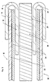
- a ferrule 10 comprising an inner tubular portion in the form of a cylinder 12 and an overlapping outer tubular portion in the form of a cylinder 14.
- the cylinders 12, 14 are electrically and mechanically joined at one of their common ends 16 by an annulus 18.
- the inner surface of the inner cylinder 12 defines a through hole 20 extending between the two ends 15, 16 of the cylinders 12, 14.
- the outer surface of the inner cylinder 12 in combination with the inner surface of the outer cylinder 14 and the annulus 18 define a cavity 22 at the end 15 of the cylinders 12, 14.
- the ferrule 10 is formed from an electrically conducting material. It is formed by drawing back an end of a hollow cylinder over itself in an overlapping manner to form the inner cylinder 12 joined at one end 16 to the outer cylinder 14.
- the ferrule 10 is shown with a cable 30 inserted.
- the cable 30 includes a jacket 32, shield 34 and signal carrier, or signal carrier twisted pairs, 36.
- the cable 30 is inserted into the ferrule 10 so that the jacket 32 and shield 34 are slid into the cavity 22, whilst the signal carrier 36 and any insulating element between the signal carrier 36 and shield 34 is/are slid through the through hole 20.
- the jacket 32 and shield 34 are stripped back by a predetermined length to allow a sufficient amount of the signal carrier 36 to extend out of an end of the through hole 20 at the end 16 of the cylinders 12, 14 for termination to a contact of a connector.
- drain wire is present, it is not stripped back with the jacket 32 and shield 34.
- the drain wire is temporarily wrapped around the signal carrier 36 and any plastic film that may be present. Subsequent to insertion into the ferrule 10, the drain wire is unwrapped from the signal carrier 36 and bent back over the ferrule 10. The wire is then trimmed flush with an end of the ferrule 10 furthest from the stripped end and may subsequently be terminated to a connector with the ferrule 10.
- any incisions be enlarged into bellmouths as is illustrated in Figures 4 and 5.
- the ferrule 10 is slid over the signal carrier 36 and any drain wire or film present.
- the jacket 32 is then held at a predetermined distance, preferably 20mm, from an end of the jacket 32.
- the ferrule 10, signal carrier 36 and any drain wire or plastic film are then revolved about the centre axis of the held cable 30 in clockwise and anticlockwise directions as is shown in Figure 4 to create the bellmouth 31 shown in Figure 5.
- an 808 connector assembly 40 is shown in an exploded, pre-terminated, view.
- the cable 30 is inserted into the ferrule 10 as described previously.
- a crimp ring 42 is then fed onto the cable past the ferrule.
- the signal carrier 36 of the cable 30 is terminated to a contact 44 of a connector 46 by inserting stripped wires and closing a lid 48.
- the length of the stripped wires are predetermined such that, once the wires are terminated, the ferrule 10 is positioned in contact with a projecting tongue 50.
- a ground plate 52 is attached to the connector 46 over the lid 48.
- the ground plate 52 has a semi cylindrical projection 54 that engages the ferrule 10 at a position opposite the tongue 50.
- the crimp ring 42 is slid back up the cable to a position where it encircles the tongue 50, the semi cylindrical projection 54 and the ferrule 10. The crimp ring 42 is then tightened to clamp everything together.
- An outer conducting body 56 is then slid over the connector 46 to complete the termination of the cable 30 to the connector assembly 40. The outer body 56 is in contact with portions of the tongue 50 and the ground plate 52 and is therefore connected to the screen 34 of the cable 30 via the ferrule 10.
- FIG 7 an enhancement of the 808 connector assembly 40 of Figure 6 is shown where the ground plate 52, the crimp ring 42, the tongue 50 and the outer body 56 are replaced by a single screening body 60 having a cylindrical projection 62.
- the screening body 60 is slid onto the cable 30 which cable 30 is then terminated to the ferrule 10 and connector 46 as described previously.
- the screening body 60 is slid up the cable 30 and over the connector 46 so that the projection 62 overlaps the ferrule 10.
- the projection is then crimped around the ferrule to secure the connector assembly 40 to the cable and also to connect the screen 34 of the cable 30 to the screening body 60 via the ferrule 10.
- connection assembly shown in Figure 6 shows a known 808 connector adapted for improved screening connection.
- the design of the ground plate 52 could be varied according to the connector it is to be used with and how it is to be attached.
- the construction of the ferrule 10 be such that the outer cylinder 14 deforms under a crimping force whilst the inner cylinder 12 remains substantially unaffected. In this way, the ferrule 10 may be crimped to the cable 30 without any disruption to the signal carrier 36 and in the case of twisted pairs will not affect the lay of the cable thereby resulting in no change in the cable data transmission performance.
Landscapes
- Cable Accessories (AREA)
- Connections Effected By Soldering, Adhesion, Or Permanent Deformation (AREA)
- Mechanical Coupling Of Light Guides (AREA)
- Multi-Conductor Connections (AREA)
- Details Of Connecting Devices For Male And Female Coupling (AREA)
- Processing Of Terminals (AREA)
Claims (9)
- Ein Verbinder mit einem elektrisch leitfähigen Verbinderkörper (56, 60) und einer Anschlußhülse (10), wobei die Anschlußhülse (10) innere und äußere röhrenförmige zylindrische Teilbereiche (12, 14) hat, die einen Hohlraum (22) definieren, in den die Abschirmung (34) beziehungsweise die Abschirmung und der Mantel (34, 32) eines abgeschirmten Kabels eingeführt werden kann bzw. können, um mit der Abschirmung (34) einen elektrischen Kontakt herzustellen, wobei die Hülse mit dem Verbinderkörper (60) verbunden werden kann, um eine elektrische Verbindung zwischen der Abschirmung und dem Körper herzustellen, wobei die Hülse (10) so ausgeführt ist, daß sie die Abschirmung beziehungsweise die Abschirmung und den Mantel des eingeführten Kabels vollständig umschließen kann, und einen ringförmigen Teilbereich (18) umfaßt, der elektrisch und mechanisch die inneren und äußeren röhrenförmigen Teilbereiche (12, 14) miteinander verbindet, dadurch gekennzeichnet, daß die Hülse (10) aus einem hohlen Zylinder geformt ist, der über sich selbst nach hinten gezogen ist, um die inneren und äußeren röhrenförmigen Teilbereiche und den ringförmigen Teilbereich zu bilden.
- Ein Verbinder nach Anspruch 1, wobei der Körper (50) ein Röhrchen (62) hat, das aus dem Körper ragt und einen ringförmigen Querschnitt hat, und wobei die Hülse (10) mit dem Röhrchen (62) verbunden werden kann, um eine elektrische Verbindung zwischen der Abschirmung und dem Körper herzustellen, wobei das Röhrchen zum Crimpen um die Hülse angepaßt ist, um eine Verbindung zwischen dem Röhrchen und der Hülse herzustellen.
- Ein Verbinder nach Anspruch 1, wobei der Körper (56) eine längliche leitfähige Zunge (50) hat, die aus dem Körper ragt, und wobei die Zunge (50) mit der Außenseite der Hülse (10) verbunden werden kann, um eine elektrische Verbindung zwischen der Abschirmung und dem Körper herzustellen, wobei der Verbinder auch eine Erdungsplatte (52) zur Verbindung von Verbinderkörper und Hülse umfaßt, wobei die Erdungsplatte einen im wesentlichen halbzylindrischen Vorsprung hat, der sich mit der Außenseite der Hülse an einer Stelle gegenüber der Zunge verbindet, wobei ein Crimpring (42) zur Sicherung der Zunge und als Vorsprung zur Hülse vorgesehen ist.
- Ein abgeschirmtes Kabel (30), das mit einem Verbinderkörper (56, 60) verbunden ist, das mit der Abschirmung (34) des abgeschirmten Kabels einen elektrischen Kontakt herstellt, wobei der Anschluß eine Anschlußhülse (10) mit inneren und äußeren röhrenförmigen zylindrischen Teilbereichen (12, 14), die einen Hohlraum (22) definieren, in den die Abschirmung (34) beziehungsweise die Abschirmung und der Mantel (34, 32) des abgeschirmten Kabels eingeführt wird bzw. werden, um mit der Abschirmung (34) einen elektrischen Kontakt herzustellen, und auch einen ringförmigen Teilbereich (18), der elektrisch und mechanisch die inneren und äußeren röhrenförmigen Teilbereiche (12, 14) miteinander verbindet, hat, und wobei die Hülse (10) sich mit dem Verbinderkörper verbindet, um einen elektrischen Kontakt mit der Abschirmung (34) und dem Körper (56, 60) herzustellen, wobei die innere Oberfläche der Kabelabschirmung die Oberfläche des inneren zylindrischen, röhrenförmigen Bereichs (12) innerhalb des Hohlraums (22) berührt, dadurch gekennzeichnet, daß das abgeschirmte Kabel ein abgeschirmtes Doppelkabel umfaßt, dessen Abschirmung (34) ein Blechröhrchen umfaßt, und daß die Hülse (10) aus einem hohlen Zylinder gebildet ist, der über sich selbst nach hinten gezogen ist, um die inneren und äußeren röhrenförmigen Teilbereiche und den ringförmigen Teilbereich zu bilden.
- Eine Methode des Verbindens einer Abschirmung eines abgeschirmten Kabels mit einem elektrischen Verbinder unter Einsatz eines Verbinders, der einen elektrisch leitfähigen Verbinderkörper und eine Anschlußhülse, die mit dem Verbinderkörper verbunden werden kann, enthält, wobei die Hülse innere und äußere zylindrische, röhrenförmige Teilbereiche hat, die einen Hohlraum definieren, in den die Abschirmung (34) beziehungsweise die Abschirmung und der Mantel eines abgeschirmten Kabels eingeführt werden kann bzw. können, um mit der Abschirmung einen elektrischen Kontakt herzustellen, wobei die Hülse auch einen ringförmigen Teilbereich, der elektrisch und mechanisch die inneren und äußeren röhrenförmigen Teilbereiche miteinander verbindet, hat, wobei die Hülse (10) aus einem hohlen Zylinder gebildet ist, der über sich selbst nach hinten gezogen ist, um die inneren und äußeren röhrenförmigen Teilbereiche und den ringförmigen Teilbereich zu bilden, dadurch gekennzeichnet, daß die Methode die folgenden Schritte umfaßt:a) Anbringen eines Einschnittes einer vorgegebenen Länge durch den Mantel am abisolierten Ende des Kabels;b) Schieben der Hülse über den abisolierten Teilbereich des Kabels;d) Einführen der Abschirmung beziehungsweise der Abschirmung und des Mantels des Kabels in den Hohlraum der Hülse;f) Zurückbiegen eines Draindrahtes des isolierten Teilbereichs des Kabels über die Hülse;g) Kürzen des Drahtes bündig mit einem Ende der Hülse, das am weitesten vom Anschlußende des Kabels ist;h) Verbinden der Hülse mit einem Verbinderkörper zum Herstellen einer elektrischen Verbindung zwischen Hülse und Körper.
- Eine Methode nach Anspruch 5, wobei der Einschnitt parallel zur Kabelachse vorgenommen wird.
- Eine Methode nach Anspruch 5 oder 6, die auch den folgenden Schritt umfaßt:c) Drehen der Hülse und des abisolierten Teilbereichs des Kabels im Verhältnis zum Mantel um eine Mittelachse des festgehaltenen Kabels, wobei der Einschnitt so geöffnet wird, daß eine Trompetenform am Ende des Mantels gebildet wird.
- Eine Methode nach Anspruch 5, 6 oder 7, die auch den folgenden Schritt umfaßt:e) Crimpen des äußeren röhrenförmigen Teilbereichs der Hülse um die Abschirmung beziehungsweise um die Abschirmung und den Mantel des Kabels.
- Eine Methode nach einem der Ansprüche 5 bis 8, wobei Schritt h) des Verbindens der Hülse mit einem Verbinderkörper auch die folgenden Schritte umfaßt:I) Befestigen einer Erdungsplatte an den Verbinderkörper;II) Verbinden der Hülse mit der Erdungsplatte.
Applications Claiming Priority (2)
| Application Number | Priority Date | Filing Date | Title |
|---|---|---|---|
| GB9719528 | 1997-09-12 | ||
| GB9719528A GB2329283A (en) | 1997-09-12 | 1997-09-12 | Screened cable terminating ferrule |
Publications (2)
| Publication Number | Publication Date |
|---|---|
| EP0902502A1 EP0902502A1 (de) | 1999-03-17 |
| EP0902502B1 true EP0902502B1 (de) | 2002-03-27 |
Family
ID=10819039
Family Applications (1)
| Application Number | Title | Priority Date | Filing Date |
|---|---|---|---|
| EP98306521A Expired - Lifetime EP0902502B1 (de) | 1997-09-12 | 1998-08-12 | Anschlusshülse für abgeschirmte Kabel |
Country Status (8)
| Country | Link |
|---|---|
| US (1) | US6152746A (de) |
| EP (1) | EP0902502B1 (de) |
| AT (1) | ATE215270T1 (de) |
| DE (1) | DE69804396T2 (de) |
| ES (1) | ES2171285T3 (de) |
| GB (1) | GB2329283A (de) |
| PT (1) | PT902502E (de) |
| ZA (1) | ZA987490B (de) |
Families Citing this family (36)
| Publication number | Priority date | Publication date | Assignee | Title |
|---|---|---|---|---|
| JP3788722B2 (ja) * | 2000-06-01 | 2006-06-21 | 株式会社オートネットワーク技術研究所 | シールドコネクタ |
| DE10121762C1 (de) * | 2001-05-04 | 2003-02-20 | Siemens Ag | Steckverbinder zum Anschließen von Koaxialleitern |
| US7844344B2 (en) | 2004-03-30 | 2010-11-30 | Medtronic, Inc. | MRI-safe implantable lead |
| JP4744419B2 (ja) * | 2006-11-10 | 2011-08-10 | 矢崎総業株式会社 | シールド端末処理方法、およびシールド端末処理構造 |
| US9044593B2 (en) | 2007-02-14 | 2015-06-02 | Medtronic, Inc. | Discontinuous conductive filler polymer-matrix composites for electromagnetic shielding |
| US7726985B2 (en) * | 2007-02-20 | 2010-06-01 | Delphi Technologies, Inc. | Shielded electric cable assembly and method |
| FR2913822B1 (fr) * | 2007-03-15 | 2011-12-23 | Cotterlaz Jean Sas | Dispositif de raccordement pour gaine de blindage electromagnetique |
| US8483842B2 (en) | 2007-04-25 | 2013-07-09 | Medtronic, Inc. | Lead or lead extension having a conductive body and conductive body contact |
| EP2019450A1 (de) * | 2007-07-26 | 2009-01-28 | 3M Innovative Properties Company | Verbinder für ein Koaxialkabel |
| US9037263B2 (en) | 2008-03-12 | 2015-05-19 | Medtronic, Inc. | System and method for implantable medical device lead shielding |
| US7868251B2 (en) * | 2008-04-08 | 2011-01-11 | Delphi Technologies, Inc. | Shielded electric cable assembly |
| EP2429630B1 (de) | 2009-04-30 | 2017-10-25 | Medtronic, Inc | Steuern einer implantierbaren medizinischen elektrode mit drehmomentübertragung durch ein lenkstilett |
| WO2010127014A1 (en) | 2009-04-30 | 2010-11-04 | Medtronic, Inc. | Detection of proper insertion of medical leads into a medical device |
| US8788061B2 (en) | 2009-04-30 | 2014-07-22 | Medtronic, Inc. | Termination of a shield within an implantable medical lead |
| CN101938061B (zh) * | 2009-07-02 | 2013-11-13 | 富士康(昆山)电脑接插件有限公司 | 线缆连接器组件 |
| JP5622307B2 (ja) * | 2010-07-05 | 2014-11-12 | 矢崎総業株式会社 | シールドコネクタ |
| JP5088427B2 (ja) * | 2011-03-02 | 2012-12-05 | 第一精工株式会社 | 電気コネクタ及び電気コネクタ組立体 |
| WO2013030955A1 (ja) * | 2011-08-30 | 2013-03-07 | 矢崎総業株式会社 | シールド電線のアース接続構造 |
| JP5823787B2 (ja) * | 2011-09-12 | 2015-11-25 | 矢崎総業株式会社 | 同軸ケーブルとシールド端子との接続構造およびその接続方法 |
| USD713585S1 (en) | 2011-09-16 | 2014-09-16 | Nord Light S.P.A. | Downlight |
| JP5848963B2 (ja) * | 2011-11-25 | 2016-01-27 | 矢崎総業株式会社 | シールド構造及びワイヤハーネス |
| WO2013158189A1 (en) | 2012-04-19 | 2013-10-24 | Medtronic, Inc. | Paired medical lead bodies with braided conductive shields having different physical parameter values |
| US8777643B2 (en) * | 2012-08-16 | 2014-07-15 | Hubbell Incorporated | Ground strap shield connector |
| DE102013009184A1 (de) * | 2013-05-31 | 2014-12-04 | Kostal Kontakt Systeme Gmbh | Kontaktelement |
| EP2849299B1 (de) * | 2013-09-11 | 2018-04-04 | Lapp Engineering & Co. | Vorrichtung zur Fixierung eines Kabels und Funktionseinheit |
| US9993638B2 (en) | 2013-12-14 | 2018-06-12 | Medtronic, Inc. | Devices, systems and methods to reduce coupling of a shield and a conductor within an implantable medical lead |
| WO2016014427A1 (en) | 2014-07-23 | 2016-01-28 | Medtronic, Inc. | Methods of shielding implantable medical leads and implantable medical lead extensions |
| EP3191175B1 (de) | 2014-07-24 | 2022-03-02 | Medtronic, Inc. | Vorrichtung zur abschirmung von implantierbaren medizinischen leitungen und leitungsverlängerungen |
| EP3242359B1 (de) * | 2016-05-04 | 2019-07-17 | MD Elektronik GmbH | Kabel |
| US10128611B2 (en) * | 2016-08-01 | 2018-11-13 | Te Connectivity Corporation | Ferrule assembly for an electrical connector |
| CN107732579B (zh) * | 2016-08-12 | 2020-01-10 | 东莞莫仕连接器有限公司 | 线缆连接器 |
| JP1682813S (ja) * | 2020-08-11 | 2021-04-05 | 整流板 | |
| JP1682810S (ja) * | 2020-08-11 | 2023-03-28 | 整流板 | |
| JP1682811S (ja) * | 2020-08-11 | 2021-04-05 | 整流板 | |
| JP1682812S (ja) * | 2020-08-11 | 2021-04-05 | 整流板 | |
| CN116936169A (zh) * | 2022-04-11 | 2023-10-24 | 益登科技股份有限公司 | 同轴缆线及其讯号传输总成 |
Family Cites Families (17)
| Publication number | Priority date | Publication date | Assignee | Title |
|---|---|---|---|---|
| GB816499A (en) * | 1956-10-17 | 1959-07-15 | Burndy Corp | Compressible insulated connector for a shielded cable |
| FR2374758A1 (fr) * | 1976-12-17 | 1978-07-13 | Bunker Ramo | Connecteur de cable coaxial |
| US4239313A (en) * | 1978-11-14 | 1980-12-16 | Parr William W | Swivel connector |
| US4329537A (en) * | 1979-08-14 | 1982-05-11 | Communications Technology Corporation | Crimp-type cable shield bonding device |
| US4453798A (en) * | 1982-06-18 | 1984-06-12 | Amp Incorporated | Shielded cable on coaxial connector |
| US4613199A (en) * | 1984-08-20 | 1986-09-23 | Solitron Devices, Inc. | Direct-crimp coaxial cable connector |
| US4822286A (en) * | 1988-05-12 | 1989-04-18 | Amp Incorporated | Hood having an integral strain relief for use with electrical connectors |
| JPH0817102B2 (ja) * | 1988-07-15 | 1996-02-21 | 日本エー・エム・ピー株式会社 | 電気コネクタ |
| US5466175A (en) * | 1992-02-27 | 1995-11-14 | Yazaki Corporation | Shield connector connecting shield cables |
| US5186655A (en) * | 1992-05-05 | 1993-02-16 | Andros Manufacturing Corporation | RF connector |
| DE4447502C2 (de) * | 1994-07-21 | 1999-09-16 | Daimler Chrysler Aerospace | Anschlußelement zur drehbeweglichen Verbindung der Komponenten eines Schutzschlauchsystems |
| JP3211587B2 (ja) * | 1994-09-27 | 2001-09-25 | 住友電装株式会社 | シールド電線のアース構造 |
| JP3097816B2 (ja) * | 1995-03-10 | 2000-10-10 | 矢崎総業株式会社 | シールド線のシースずれ防止構造 |
| US5895291A (en) * | 1995-11-02 | 1999-04-20 | The Whitaker Corporation | Shielded cable connector assembly |
| US5679926A (en) * | 1996-02-22 | 1997-10-21 | General Motors Corporation | Sleeve retainer for sensor |
| US5921700A (en) * | 1997-01-24 | 1999-07-13 | True Temper Hardware Company | Handle to tool head transition piece |
| US5929383A (en) * | 1997-04-07 | 1999-07-27 | Thomas & Betts Corporation | Rotationally unrestrained grounding coupling for external grounding of fittings |
-
1997
- 1997-09-12 GB GB9719528A patent/GB2329283A/en not_active Withdrawn
-
1998
- 1998-08-12 PT PT98306521T patent/PT902502E/pt unknown
- 1998-08-12 AT AT98306521T patent/ATE215270T1/de not_active IP Right Cessation
- 1998-08-12 ES ES98306521T patent/ES2171285T3/es not_active Expired - Lifetime
- 1998-08-12 EP EP98306521A patent/EP0902502B1/de not_active Expired - Lifetime
- 1998-08-12 DE DE69804396T patent/DE69804396T2/de not_active Expired - Fee Related
- 1998-08-19 ZA ZA987490A patent/ZA987490B/xx unknown
- 1998-09-01 US US09/146,382 patent/US6152746A/en not_active Expired - Fee Related
Also Published As
| Publication number | Publication date |
|---|---|
| ES2171285T3 (es) | 2002-09-01 |
| ATE215270T1 (de) | 2002-04-15 |
| EP0902502A1 (de) | 1999-03-17 |
| PT902502E (pt) | 2002-08-30 |
| ZA987490B (en) | 1999-02-22 |
| GB9719528D0 (en) | 1997-11-19 |
| DE69804396T2 (de) | 2002-11-28 |
| US6152746A (en) | 2000-11-28 |
| GB2329283A (en) | 1999-03-17 |
| DE69804396D1 (de) | 2002-05-02 |
Similar Documents
| Publication | Publication Date | Title |
|---|---|---|
| EP0902502B1 (de) | Anschlusshülse für abgeschirmte Kabel | |
| US6786774B2 (en) | Two-conductor cable and phone plug assembly | |
| US2798113A (en) | Shield connectors | |
| CN101461103B (zh) | 用于电缆连接器的保持套圈 | |
| US5123864A (en) | Coaxial contact with sleeve | |
| EP0330357A1 (de) | Ein mit einer Anschlussklemme versehenes elektrisches Koaxialkabel und Verfahren zu dessen Herstellung | |
| US6485335B1 (en) | Electrical connection | |
| GB2315167A (en) | Electrical connectors and cable termination system | |
| JP7042977B2 (ja) | コネクタ | |
| US4568401A (en) | Method of making a free floating sheathed cable | |
| US5768771A (en) | System for terminating the shield of a high speed cable | |
| JP7191127B2 (ja) | 信号ケーブル | |
| EP0845161A1 (de) | Zugentlastungspresshülse mit haltezunge | |
| CA1081336A (en) | Connector for coupling a ground conductor to the shield of a shielded conductor | |
| US11476622B2 (en) | Shielded telecommunications connector | |
| CA1124347A (en) | Connector assembly for electrical conduit | |
| US20230178928A1 (en) | Shielded electrically conductive path | |
| JP2606411Y2 (ja) | 中空線の接続構造 | |
| JPH0245976Y2 (de) | ||
| US20230120355A1 (en) | Shield termination system that eliminates cable shield drain-wires | |
| JPH08340615A (ja) | シールド線のアース接続構造 | |
| JPH06275344A (ja) | 高周波接栓 | |
| JP2010140809A (ja) | 同軸ケーブル用コネクタ | |
| JPH03105880A (ja) | 同軸コネクタ | |
| MXPA97001565A (en) | System to complete the shield of a cable aalta veloci |
Legal Events
| Date | Code | Title | Description |
|---|---|---|---|
| PUAI | Public reference made under article 153(3) epc to a published international application that has entered the european phase |
Free format text: ORIGINAL CODE: 0009012 |
|
| AK | Designated contracting states |
Kind code of ref document: A1 Designated state(s): AT BE CH DE ES FR GB IE IT LI NL PT |
|
| AX | Request for extension of the european patent |
Free format text: AL;LT;LV;MK;RO;SI |
|
| 17P | Request for examination filed |
Effective date: 19990303 |
|
| AKX | Designation fees paid |
Free format text: AT BE CH DE ES FR GB IE IT LI NL PT |
|
| 17Q | First examination report despatched |
Effective date: 19991203 |
|
| GRAG | Despatch of communication of intention to grant |
Free format text: ORIGINAL CODE: EPIDOS AGRA |
|
| GRAG | Despatch of communication of intention to grant |
Free format text: ORIGINAL CODE: EPIDOS AGRA |
|
| GRAH | Despatch of communication of intention to grant a patent |
Free format text: ORIGINAL CODE: EPIDOS IGRA |
|
| GRAH | Despatch of communication of intention to grant a patent |
Free format text: ORIGINAL CODE: EPIDOS IGRA |
|
| REG | Reference to a national code |
Ref country code: GB Ref legal event code: IF02 |
|
| GRAA | (expected) grant |
Free format text: ORIGINAL CODE: 0009210 |
|
| AK | Designated contracting states |
Kind code of ref document: B1 Designated state(s): AT BE CH DE ES FR GB IE IT LI NL PT |
|
| REF | Corresponds to: |
Ref document number: 215270 Country of ref document: AT Date of ref document: 20020415 Kind code of ref document: T |
|
| REG | Reference to a national code |
Ref country code: CH Ref legal event code: EP |
|
| REG | Reference to a national code |
Ref country code: CH Ref legal event code: NV Representative=s name: TROESCH SCHEIDEGGER WERNER AG |
|
| REF | Corresponds to: |
Ref document number: 69804396 Country of ref document: DE Date of ref document: 20020502 |
|
| REG | Reference to a national code |
Ref country code: IE Ref legal event code: FG4D |
|
| ET | Fr: translation filed | ||
| REG | Reference to a national code |
Ref country code: PT Ref legal event code: SC4A Free format text: AVAILABILITY OF NATIONAL TRANSLATION Effective date: 20020531 |
|
| REG | Reference to a national code |
Ref country code: ES Ref legal event code: FG2A Ref document number: 2171285 Country of ref document: ES Kind code of ref document: T3 |
|
| PLBE | No opposition filed within time limit |
Free format text: ORIGINAL CODE: 0009261 |
|
| STAA | Information on the status of an ep patent application or granted ep patent |
Free format text: STATUS: NO OPPOSITION FILED WITHIN TIME LIMIT |
|
| 26N | No opposition filed |
Effective date: 20021230 |
|
| PGFP | Annual fee paid to national office [announced via postgrant information from national office to epo] |
Ref country code: DE Payment date: 20070822 Year of fee payment: 10 |
|
| PGFP | Annual fee paid to national office [announced via postgrant information from national office to epo] |
Ref country code: IE Payment date: 20070824 Year of fee payment: 10 |
|
| PGFP | Annual fee paid to national office [announced via postgrant information from national office to epo] |
Ref country code: ES Payment date: 20070830 Year of fee payment: 10 |
|
| PGFP | Annual fee paid to national office [announced via postgrant information from national office to epo] |
Ref country code: CH Payment date: 20070815 Year of fee payment: 10 Ref country code: AT Payment date: 20070816 Year of fee payment: 10 |
|
| PGFP | Annual fee paid to national office [announced via postgrant information from national office to epo] |
Ref country code: GB Payment date: 20070823 Year of fee payment: 10 |
|
| PGFP | Annual fee paid to national office [announced via postgrant information from national office to epo] |
Ref country code: NL Payment date: 20070814 Year of fee payment: 10 Ref country code: IT Payment date: 20070824 Year of fee payment: 10 Ref country code: BE Payment date: 20070905 Year of fee payment: 10 |
|
| PGFP | Annual fee paid to national office [announced via postgrant information from national office to epo] |
Ref country code: FR Payment date: 20070812 Year of fee payment: 10 |
|
| REG | Reference to a national code |
Ref country code: PT Ref legal event code: MM4A Free format text: LAPSE DUE TO NON-PAYMENT OF FEES Effective date: 20090212 |
|
| REG | Reference to a national code |
Ref country code: CH Ref legal event code: PL |
|
| GBPC | Gb: european patent ceased through non-payment of renewal fee |
Effective date: 20080812 |
|
| PG25 | Lapsed in a contracting state [announced via postgrant information from national office to epo] |
Ref country code: AT Free format text: LAPSE BECAUSE OF NON-PAYMENT OF DUE FEES Effective date: 20080812 |
|
| NLV4 | Nl: lapsed or anulled due to non-payment of the annual fee |
Effective date: 20090301 |
|
| REG | Reference to a national code |
Ref country code: IE Ref legal event code: MM4A |
|
| PG25 | Lapsed in a contracting state [announced via postgrant information from national office to epo] |
Ref country code: PT Free format text: LAPSE BECAUSE OF NON-PAYMENT OF DUE FEES Effective date: 20090212 Ref country code: NL Free format text: LAPSE BECAUSE OF NON-PAYMENT OF DUE FEES Effective date: 20090301 |
|
| REG | Reference to a national code |
Ref country code: FR Ref legal event code: ST Effective date: 20090430 |
|
| PG25 | Lapsed in a contracting state [announced via postgrant information from national office to epo] |
Ref country code: LI Free format text: LAPSE BECAUSE OF NON-PAYMENT OF DUE FEES Effective date: 20080831 Ref country code: CH Free format text: LAPSE BECAUSE OF NON-PAYMENT OF DUE FEES Effective date: 20080831 |
|
| PG25 | Lapsed in a contracting state [announced via postgrant information from national office to epo] |
Ref country code: IE Free format text: LAPSE BECAUSE OF NON-PAYMENT OF DUE FEES Effective date: 20080812 Ref country code: BE Free format text: LAPSE BECAUSE OF NON-PAYMENT OF DUE FEES Effective date: 20080831 |
|
| PG25 | Lapsed in a contracting state [announced via postgrant information from national office to epo] |
Ref country code: IT Free format text: LAPSE BECAUSE OF NON-PAYMENT OF DUE FEES Effective date: 20080812 Ref country code: FR Free format text: LAPSE BECAUSE OF NON-PAYMENT OF DUE FEES Effective date: 20080901 Ref country code: DE Free format text: LAPSE BECAUSE OF NON-PAYMENT OF DUE FEES Effective date: 20090303 |
|
| REG | Reference to a national code |
Ref country code: ES Ref legal event code: FD2A Effective date: 20080813 |
|
| PG25 | Lapsed in a contracting state [announced via postgrant information from national office to epo] |
Ref country code: GB Free format text: LAPSE BECAUSE OF NON-PAYMENT OF DUE FEES Effective date: 20080812 |
|
| PGFP | Annual fee paid to national office [announced via postgrant information from national office to epo] |
Ref country code: PT Payment date: 20070730 Year of fee payment: 10 |
|
| PG25 | Lapsed in a contracting state [announced via postgrant information from national office to epo] |
Ref country code: ES Free format text: LAPSE BECAUSE OF NON-PAYMENT OF DUE FEES Effective date: 20080813 |