EP0902346A2 - Modulares feldbusgesteuertes Automatisierungsgerät - Google Patents
Modulares feldbusgesteuertes Automatisierungsgerät Download PDFInfo
- Publication number
- EP0902346A2 EP0902346A2 EP98116594A EP98116594A EP0902346A2 EP 0902346 A2 EP0902346 A2 EP 0902346A2 EP 98116594 A EP98116594 A EP 98116594A EP 98116594 A EP98116594 A EP 98116594A EP 0902346 A2 EP0902346 A2 EP 0902346A2
- Authority
- EP
- European Patent Office
- Prior art keywords
- module
- external contacts
- automation device
- head module
- head
- Prior art date
- Legal status (The legal status is an assumption and is not a legal conclusion. Google has not performed a legal analysis and makes no representation as to the accuracy of the status listed.)
- Granted
Links
Images

Classifications
-
- H—ELECTRICITY
- H05—ELECTRIC TECHNIQUES NOT OTHERWISE PROVIDED FOR
- H05K—PRINTED CIRCUITS; CASINGS OR CONSTRUCTIONAL DETAILS OF ELECTRIC APPARATUS; MANUFACTURE OF ASSEMBLAGES OF ELECTRICAL COMPONENTS
- H05K7/00—Constructional details common to different types of electric apparatus
- H05K7/14—Mounting supporting structure in casing or on frame or rack
- H05K7/1462—Mounting supporting structure in casing or on frame or rack for programmable logic controllers [PLC] for automation or industrial process control
- H05K7/1465—Modular PLC assemblies with separable functional units
-
- G—PHYSICS
- G05—CONTROLLING; REGULATING
- G05B—CONTROL OR REGULATING SYSTEMS IN GENERAL; FUNCTIONAL ELEMENTS OF SUCH SYSTEMS; MONITORING OR TESTING ARRANGEMENTS FOR SUCH SYSTEMS OR ELEMENTS
- G05B19/00—Program-control systems
- G05B19/02—Program-control systems electric
- G05B19/04—Program control other than numerical control, i.e. in sequence controllers or logic controllers
- G05B19/042—Program control other than numerical control, i.e. in sequence controllers or logic controllers using digital processors
-
- H—ELECTRICITY
- H05—ELECTRIC TECHNIQUES NOT OTHERWISE PROVIDED FOR
- H05K—PRINTED CIRCUITS; CASINGS OR CONSTRUCTIONAL DETAILS OF ELECTRIC APPARATUS; MANUFACTURE OF ASSEMBLAGES OF ELECTRICAL COMPONENTS
- H05K7/00—Constructional details common to different types of electric apparatus
- H05K7/14—Mounting supporting structure in casing or on frame or rack
- H05K7/1462—Mounting supporting structure in casing or on frame or rack for programmable logic controllers [PLC] for automation or industrial process control
- H05K7/1468—Mechanical features of input/output (I/O) modules
- H05K7/1472—Bus coupling modules, e.g. bus distribution modules
-
- G—PHYSICS
- G05—CONTROLLING; REGULATING
- G05B—CONTROL OR REGULATING SYSTEMS IN GENERAL; FUNCTIONAL ELEMENTS OF SUCH SYSTEMS; MONITORING OR TESTING ARRANGEMENTS FOR SUCH SYSTEMS OR ELEMENTS
- G05B2219/00—Program-control systems
- G05B2219/10—Plc systems
- G05B2219/15—Plc structure of the system
- G05B2219/15078—Modules, construction of system
-
- G—PHYSICS
- G05—CONTROLLING; REGULATING
- G05B—CONTROL OR REGULATING SYSTEMS IN GENERAL; FUNCTIONAL ELEMENTS OF SUCH SYSTEMS; MONITORING OR TESTING ARRANGEMENTS FOR SUCH SYSTEMS OR ELEMENTS
- G05B2219/00—Program-control systems
- G05B2219/20—Pc systems
- G05B2219/25—Pc structure of the system
- G05B2219/25314—Modular structure, modules
Definitions
- the present invention relates to a fieldbus-controlled automation device to control and / or monitor a technical process.
- the terminals are Part of the individual function module, so that when replacing of a function module the ones connected to the terminals Cables must be disconnected so that there is a permanent wiring is not given.
- the object of the present invention is therefore to a fieldbus controlled automation device to indicate that can be built both compact and granular.
- This task is accomplished with a fieldbus controlled automation device of the type mentioned above with a basic module, a Head module with external contacts and at least one function module without external contacts, the head module or the function module contactable with the base module is solved in that the external contacts of the head module for connecting a power supply and / or for communicative purposes Connect to other electrical devices provided are that the head module to control the at least a functional module is effective and that the base module external contacts for connecting external devices - in particular Actuators or sensors for control and / or technical Process - has that spatially assigned to a functional module are and are connected to this electrically conductive.
- a functional module that has a flush arrangement is one particularly compact design of the automation device on the one hand and a mutual stabilization of the neighboring ones Function modules on the other hand.
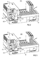
- the external contacts of the head module are spatially related to each other are arranged so that when contacting the external contacts a compulsory course of action due to the design results in contacting the head module in only one defined conditions possible in a dragging manner. So can e.g. the external contact for the ground and / or shield connection only be contacted before the external contacts for the supply voltage and the communicative connection contacted are.
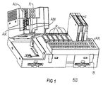
- the automation device AG at least exists from a basic module B, one with this electrically and mechanically detachably connectable head module K and at least one can be connected to the base module B electrically and mechanically detachably Function module F.
- the base module B also has external contacts A, which Connecting external devices, especially the actuators mentioned or sensors, for controlling and / or monitoring the enable technical process. Likewise, that points Head module K external contacts for connecting a power supply and / or for communicative connection with others electrical devices, which, however, cannot be seen in the FIG are.
- the function or electronics module F is on a receiving position P of the base module B.
- the base module B has a large number in the exemplary embodiment of recording positions P for recording one functional module each F on.
- the function module F itself has no external contacts but is in a capsule-shaped housing included, from which the contact means to the electrically conductive Contact with appropriate counter contact means of the base module B protrude.
- the head module K is also encapsulated in a housing, the openings for contacting the external contacts or openings for a contact means for contacting the corresponding one Has contact means of the base module B.
- the head module K enables permanent wiring and is simple solvable. Through a uniform interface, head modules K for different bus systems for communicative purposes Connect with other electrical devices become. Since the head module K does not contain any peripheral electronics, there is a favorable structure in terms of separation Electronics and peripherals, and thus better cooling and better EMC resistance.
- the present invention can be summarized as follows describe: It is a fieldbus controlled automation device AG to control and / or monitor the technical Process with a basic module B, a head module K with external contacts and at least one function module F without external contacts specified, the head module K or the functional module F electrically contactable with the base module B. is.
Landscapes
- Engineering & Computer Science (AREA)
- Automation & Control Theory (AREA)
- Microelectronics & Electronic Packaging (AREA)
- Physics & Mathematics (AREA)
- General Physics & Mathematics (AREA)
- Paper (AREA)
- Programmable Controllers (AREA)
- Electrotherapy Devices (AREA)
- Details Of Connecting Devices For Male And Female Coupling (AREA)
- Testing And Monitoring For Control Systems (AREA)
- Control Of Eletrric Generators (AREA)
- Connections Arranged To Contact A Plurality Of Conductors (AREA)
Abstract
Description
- FIG 1
- ein feldbusgesteuertes Automatisierungsgerät und
- FIGen 2 bis 5
- den konstruktionsbedingt zwangsweisen Handlungsablauf beim Kontaktieren und Dekontaktieren der Außenanschlüsse des Kopfmoduls.
Claims (4)
- Feldbusgesteuertes Automatisierungsgerät (AG) zur Steuerung und/oder Überwachung eines technischen Prozesses mit einem Basismodul (B), einem Kopfmodul (K) mit Außenkontakten und mindestens einem Funktionsmodul (F) ohne Außenkontakte, wobei das Kopfmodul (K) bzw. das Funktionsmodul (F) mit dem Basismodul (B) elektrisch leitend kontaktierbar ist,wobei die Außenkontakte das Kopfmoduls (K) zum Anschließen einer Spannungsversorgung und/oder zum kommunikativen Verbinden mit weiteren elektrischen Geräten vorgesehen sind und wobei das Kopfmodul (K) zur Ansteuerung des mindestens einen Funktionsmoduls (F) wirksam ist,wobei das Basismodul (B) Außenkontakte zum Anschließen externer Geräte - insbesondere Aktoren oder Sensoren zur Steuerung und/oder Überwachung des technischen Prozesses - aufweist, die einem Funktionsmodul (F) räumlich zugeordnet sind und mit diesem elektrisch leitend verbunden sind.
- Feldbusgesteuertes Automatisierungsgerät nach Anspruch 1, dadurch gekennzeichnet, daß das Basismodul (B) Aufnahmepositionen (P) zur Aufnahme des mindestens einen Funktionsmoduls (F) aufweist, die eine bündige Anordnung benachbarter Funktionsmodule (F) ermöglicht.
- Feldbusgesteuertes Automatisierungsgerät nach Anspruch 1 oder 2, dadurch gekennzeichnet, daß die Außenkontakte des Kopfmoduls (K) räumlich zueinander so angeordnet sind, daß sich beim Kontaktieren der Außenkontakte ein konstruktionsbedingt zwangsweiser Handlungsablauf ergibt.
- Feldbusgesteuertes Automatisierungsgerät nach Anspruch 3, dadurch gekennzeichnet, daß ein elektrisches bzw. mechanisches Kontaktieren bzw. Dekontaktieren des Kopfmoduls (K) mit dem Basismodul (B) nur unter Einhaltung des konstruktionsbedingt zwangsweisen Handlungsablaufs beim Kontaktieren bzw. Dekontaktieren der Außenanschlüsse des Kopfmoduls (K) möglich ist.
Applications Claiming Priority (2)
| Application Number | Priority Date | Filing Date | Title |
|---|---|---|---|
| DE29716575U DE29716575U1 (de) | 1997-09-15 | 1997-09-15 | Feldbusgesteuertes Automatisierungsgerät |
| DE29716575U | 1997-09-15 |
Publications (3)
| Publication Number | Publication Date |
|---|---|
| EP0902346A2 true EP0902346A2 (de) | 1999-03-17 |
| EP0902346A3 EP0902346A3 (de) | 2000-07-19 |
| EP0902346B1 EP0902346B1 (de) | 2002-12-04 |
Family
ID=8046031
Family Applications (1)
| Application Number | Title | Priority Date | Filing Date |
|---|---|---|---|
| EP98116594A Expired - Lifetime EP0902346B1 (de) | 1997-09-15 | 1998-09-02 | Modulares feldbusgesteuertes Automatisierungsgerät |
Country Status (4)
| Country | Link |
|---|---|
| EP (1) | EP0902346B1 (de) |
| AT (1) | ATE229195T1 (de) |
| DE (2) | DE29716575U1 (de) |
| ES (1) | ES2189055T3 (de) |
Cited By (2)
| Publication number | Priority date | Publication date | Assignee | Title |
|---|---|---|---|---|
| WO2001031688A3 (de) * | 1999-10-29 | 2001-09-20 | Siemens Ag | Verfahren zum austausch eines baugruppenrahmens mittels eines hilfsbaugruppenrahmens |
| WO2018219400A1 (de) * | 2017-05-31 | 2018-12-06 | Robodev Gmbh | Modular aufgebautes feldgerät |
Families Citing this family (7)
| Publication number | Priority date | Publication date | Assignee | Title |
|---|---|---|---|---|
| DE19816170C5 (de) * | 1998-04-09 | 2004-09-23 | Sew-Eurodrive Gmbh & Co | Steuerungsmodul |
| DE10135980C1 (de) * | 2001-07-24 | 2003-04-24 | Abb Patent Gmbh | Anordnung zum Anschluß von dezentral und prozessnah angeordneten Feldgeräten an eine entfernte zentrale Einrichtung |
| DE102004056243A1 (de) | 2004-11-22 | 2006-05-24 | Abb Patent Gmbh | Modulares Automatisierungssystem |
| JP4232796B2 (ja) * | 2005-11-29 | 2009-03-04 | セイコーエプソン株式会社 | ロボット制御装置及びロボットシステム |
| CN100519101C (zh) * | 2005-11-29 | 2009-07-29 | 精工爱普生株式会社 | 机器人控制装置及机器人系统 |
| DE102009046552B4 (de) * | 2009-11-10 | 2014-03-06 | EDS Systemtechnik Gesellschaft für elektronische Datenverarbeitungsanlagen mbH | Prozessdatenrechner |
| JP5983696B2 (ja) * | 2014-01-29 | 2016-09-06 | 横河電機株式会社 | 電子機器 |
Family Cites Families (3)
| Publication number | Priority date | Publication date | Assignee | Title |
|---|---|---|---|---|
| DE3429020A1 (de) * | 1984-08-07 | 1986-02-20 | Ifm Electronic Gmbh, 4300 Essen | Programmierbare steuerung |
| DE4438806C1 (de) * | 1994-10-31 | 1996-03-21 | Weidmueller Interface | Modulare Steuerungsanlage mit Busleiter |
| DE4440102C1 (de) * | 1994-11-10 | 1996-05-15 | Weidmueller Interface | Modulare Steuerungsanlage mit integriertem Feldbusanschluß |
-
1997
- 1997-09-15 DE DE29716575U patent/DE29716575U1/de not_active Expired - Lifetime
-
1998
- 1998-09-02 DE DE59806506T patent/DE59806506D1/de not_active Expired - Lifetime
- 1998-09-02 EP EP98116594A patent/EP0902346B1/de not_active Expired - Lifetime
- 1998-09-02 AT AT98116594T patent/ATE229195T1/de not_active IP Right Cessation
- 1998-09-02 ES ES98116594T patent/ES2189055T3/es not_active Expired - Lifetime
Cited By (4)
| Publication number | Priority date | Publication date | Assignee | Title |
|---|---|---|---|---|
| WO2001031688A3 (de) * | 1999-10-29 | 2001-09-20 | Siemens Ag | Verfahren zum austausch eines baugruppenrahmens mittels eines hilfsbaugruppenrahmens |
| WO2018219400A1 (de) * | 2017-05-31 | 2018-12-06 | Robodev Gmbh | Modular aufgebautes feldgerät |
| CN110651536A (zh) * | 2017-05-31 | 2020-01-03 | 罗博德夫公司 | 模块化结构的现场设备 |
| US10921867B2 (en) | 2017-05-31 | 2021-02-16 | Robodev Gmbh | Field device of modular construction |
Also Published As
| Publication number | Publication date |
|---|---|
| ATE229195T1 (de) | 2002-12-15 |
| EP0902346A3 (de) | 2000-07-19 |
| DE29716575U1 (de) | 1997-11-13 |
| EP0902346B1 (de) | 2002-12-04 |
| DE59806506D1 (de) | 2003-01-16 |
| ES2189055T3 (es) | 2003-07-01 |
Similar Documents
| Publication | Publication Date | Title |
|---|---|---|
| EP0709932B1 (de) | Modulare Steuerungsanlage mit Busleiter z. B. zur Gebäudeautomatisierung | |
| EP0709933B1 (de) | Modulare Steuerungsanlage mit Busleiter | |
| EP0314949B1 (de) | Elektrische Funktionsgruppe für ein Fahrzeug | |
| EP1029390B1 (de) | Kommunikationsfähige schaltgeräteeinheit | |
| DE4440102C1 (de) | Modulare Steuerungsanlage mit integriertem Feldbusanschluß | |
| EP0710064B1 (de) | Feldbusanschlussmodul | |
| EP0666631B1 (de) | Speisesystem für einen Feldbus | |
| WO1998026640A2 (de) | Elektrisches gerät mit modularer aufbautechnik | |
| EP1917672B1 (de) | Verbindungssystem mit einem elektromagnetischen schaltgerät, insbesondere schütz, und einem stecker | |
| EP0902346B1 (de) | Modulares feldbusgesteuertes Automatisierungsgerät | |
| EP0943165B1 (de) | Schaltschrank | |
| DE4323440A1 (de) | Elektronisches Gerät, insbesondere Automatisierungsgerät | |
| EP0493740B1 (de) | Anschlussmodul für eine Verteilereinrichtung, insbesondere für den Hauptverteiler von Fernmeldeeinrichtungen | |
| EP1474853B1 (de) | Elektrischer leistungsschalter mit einer anschlussvorrichtung für hilfsstromkreise | |
| DE202022105775U1 (de) | Modulare elektronische Sicherungen und Sicherungsbox | |
| EP0769679A1 (de) | Einbau-Mehrkanalschreiber | |
| EP3660603B1 (de) | Busfähiges aneinanderreihbares funktionsmodul | |
| EP0750802B1 (de) | Schaltverteiler zum ein- und ausschalten elektrischer verbraucher | |
| DE4013815C2 (de) | Steuerschaltung für Maschinen | |
| EP0888707B1 (de) | Baugruppe mit einer schaltungsanordnung | |
| DE4316291A1 (de) | Elektronisches Gerät, insbesondere Automatisierungsgerät | |
| EP1282348B1 (de) | Anschlusseinrichtung für die Hausleittechnik | |
| DE102006056255B4 (de) | Versorgungsmodul für Servomotoren, Schaltschrankanordnung und elektrisches System | |
| EP0593995A1 (de) | Vorrichtung zur Kraftstromversorgung von Stromverbrauchern und ein Verfahren dafür | |
| EP1808878B1 (de) | Elektrische Einrichtung mit Ausschaltung des Laststromkreises in explosionsgefährdeter Umgebung |
Legal Events
| Date | Code | Title | Description |
|---|---|---|---|
| PUAI | Public reference made under article 153(3) epc to a published international application that has entered the european phase |
Free format text: ORIGINAL CODE: 0009012 |
|
| AK | Designated contracting states |
Kind code of ref document: A2 Designated state(s): AT CH DE ES FR GB LI |
|
| AX | Request for extension of the european patent |
Free format text: AL;LT;LV;MK;RO;SI |
|
| PUAL | Search report despatched |
Free format text: ORIGINAL CODE: 0009013 |
|
| AK | Designated contracting states |
Kind code of ref document: A3 Designated state(s): AT BE CH CY DE DK ES FI FR GB GR IE IT LI LU MC NL PT SE |
|
| AX | Request for extension of the european patent |
Free format text: AL;LT;LV;MK;RO;SI |
|
| RIC1 | Information provided on ipc code assigned before grant |
Free format text: 7G 05B 19/418 A, 7H 05K 7/14 B |
|
| 17P | Request for examination filed |
Effective date: 20010118 |
|
| AKX | Designation fees paid | ||
| RBV | Designated contracting states (corrected) |
Designated state(s): AT CH DE ES FR GB LI |
|
| REG | Reference to a national code |
Ref country code: DE Ref legal event code: 8566 |
|
| 17Q | First examination report despatched |
Effective date: 20010711 |
|
| GRAG | Despatch of communication of intention to grant |
Free format text: ORIGINAL CODE: EPIDOS AGRA |
|
| GRAG | Despatch of communication of intention to grant |
Free format text: ORIGINAL CODE: EPIDOS AGRA |
|
| GRAH | Despatch of communication of intention to grant a patent |
Free format text: ORIGINAL CODE: EPIDOS IGRA |
|
| GRAH | Despatch of communication of intention to grant a patent |
Free format text: ORIGINAL CODE: EPIDOS IGRA |
|
| GRAA | (expected) grant |
Free format text: ORIGINAL CODE: 0009210 |
|
| AK | Designated contracting states |
Kind code of ref document: B1 Designated state(s): AT CH DE ES FR GB LI |
|
| REF | Corresponds to: |
Ref document number: 229195 Country of ref document: AT Date of ref document: 20021215 Kind code of ref document: T |
|
| REG | Reference to a national code |
Ref country code: GB Ref legal event code: FG4D Free format text: NOT ENGLISH |
|
| REG | Reference to a national code |
Ref country code: CH Ref legal event code: NV Representative=s name: SIEMENS SCHWEIZ AG Ref country code: CH Ref legal event code: EP |
|
| GBT | Gb: translation of ep patent filed (gb section 77(6)(a)/1977) |
Effective date: 20021204 |
|
| REF | Corresponds to: |
Ref document number: 59806506 Country of ref document: DE Date of ref document: 20030116 |
|
| REG | Reference to a national code |
Ref country code: ES Ref legal event code: FG2A Ref document number: 2189055 Country of ref document: ES Kind code of ref document: T3 |
|
| ET | Fr: translation filed | ||
| PLBE | No opposition filed within time limit |
Free format text: ORIGINAL CODE: 0009261 |
|
| STAA | Information on the status of an ep patent application or granted ep patent |
Free format text: STATUS: NO OPPOSITION FILED WITHIN TIME LIMIT |
|
| 26N | No opposition filed |
Effective date: 20030905 |
|
| PGFP | Annual fee paid to national office [announced via postgrant information from national office to epo] |
Ref country code: CH Payment date: 20031203 Year of fee payment: 6 |
|
| PGFP | Annual fee paid to national office [announced via postgrant information from national office to epo] |
Ref country code: AT Payment date: 20040831 Year of fee payment: 7 |
|
| PGFP | Annual fee paid to national office [announced via postgrant information from national office to epo] |
Ref country code: ES Payment date: 20040915 Year of fee payment: 7 |
|
| PG25 | Lapsed in a contracting state [announced via postgrant information from national office to epo] |
Ref country code: LI Free format text: LAPSE BECAUSE OF NON-PAYMENT OF DUE FEES Effective date: 20040930 Ref country code: CH Free format text: LAPSE BECAUSE OF NON-PAYMENT OF DUE FEES Effective date: 20040930 |
|
| REG | Reference to a national code |
Ref country code: CH Ref legal event code: PL |
|
| PG25 | Lapsed in a contracting state [announced via postgrant information from national office to epo] |
Ref country code: AT Free format text: LAPSE BECAUSE OF NON-PAYMENT OF DUE FEES Effective date: 20050902 |
|
| PG25 | Lapsed in a contracting state [announced via postgrant information from national office to epo] |
Ref country code: ES Free format text: LAPSE BECAUSE OF NON-PAYMENT OF DUE FEES Effective date: 20050903 |
|
| REG | Reference to a national code |
Ref country code: ES Ref legal event code: FD2A Effective date: 20050903 |
|
| PGFP | Annual fee paid to national office [announced via postgrant information from national office to epo] |
Ref country code: DE Payment date: 20101119 Year of fee payment: 13 |
|
| PGFP | Annual fee paid to national office [announced via postgrant information from national office to epo] |
Ref country code: GB Payment date: 20110915 Year of fee payment: 14 Ref country code: FR Payment date: 20111005 Year of fee payment: 14 |
|
| GBPC | Gb: european patent ceased through non-payment of renewal fee |
Effective date: 20120902 |
|
| REG | Reference to a national code |
Ref country code: FR Ref legal event code: ST Effective date: 20130531 |
|
| PG25 | Lapsed in a contracting state [announced via postgrant information from national office to epo] |
Ref country code: GB Free format text: LAPSE BECAUSE OF NON-PAYMENT OF DUE FEES Effective date: 20120902 Ref country code: DE Free format text: LAPSE BECAUSE OF NON-PAYMENT OF DUE FEES Effective date: 20130403 |
|
| PG25 | Lapsed in a contracting state [announced via postgrant information from national office to epo] |
Ref country code: FR Free format text: LAPSE BECAUSE OF NON-PAYMENT OF DUE FEES Effective date: 20121001 |
|
| REG | Reference to a national code |
Ref country code: DE Ref legal event code: R119 Ref document number: 59806506 Country of ref document: DE Effective date: 20130403 |