EP0902346A2 - Modular field bus controlled automation device - Google Patents
Modular field bus controlled automation device Download PDFInfo
- Publication number
- EP0902346A2 EP0902346A2 EP98116594A EP98116594A EP0902346A2 EP 0902346 A2 EP0902346 A2 EP 0902346A2 EP 98116594 A EP98116594 A EP 98116594A EP 98116594 A EP98116594 A EP 98116594A EP 0902346 A2 EP0902346 A2 EP 0902346A2
- Authority
- EP
- European Patent Office
- Prior art keywords
- module
- external contacts
- automation device
- head module
- head
- Prior art date
- Legal status (The legal status is an assumption and is not a legal conclusion. Google has not performed a legal analysis and makes no representation as to the accuracy of the status listed.)
- Granted
Links
Images

Classifications
-
- H—ELECTRICITY
- H05—ELECTRIC TECHNIQUES NOT OTHERWISE PROVIDED FOR
- H05K—PRINTED CIRCUITS; CASINGS OR CONSTRUCTIONAL DETAILS OF ELECTRIC APPARATUS; MANUFACTURE OF ASSEMBLAGES OF ELECTRICAL COMPONENTS
- H05K7/00—Constructional details common to different types of electric apparatus
- H05K7/14—Mounting supporting structure in casing or on frame or rack
- H05K7/1462—Mounting supporting structure in casing or on frame or rack for programmable logic controllers [PLC] for automation or industrial process control
- H05K7/1465—Modular PLC assemblies with separable functional units
-
- G—PHYSICS
- G05—CONTROLLING; REGULATING
- G05B—CONTROL OR REGULATING SYSTEMS IN GENERAL; FUNCTIONAL ELEMENTS OF SUCH SYSTEMS; MONITORING OR TESTING ARRANGEMENTS FOR SUCH SYSTEMS OR ELEMENTS
- G05B19/00—Program-control systems
- G05B19/02—Program-control systems electric
- G05B19/04—Program control other than numerical control, i.e. in sequence controllers or logic controllers
- G05B19/042—Program control other than numerical control, i.e. in sequence controllers or logic controllers using digital processors
-
- H—ELECTRICITY
- H05—ELECTRIC TECHNIQUES NOT OTHERWISE PROVIDED FOR
- H05K—PRINTED CIRCUITS; CASINGS OR CONSTRUCTIONAL DETAILS OF ELECTRIC APPARATUS; MANUFACTURE OF ASSEMBLAGES OF ELECTRICAL COMPONENTS
- H05K7/00—Constructional details common to different types of electric apparatus
- H05K7/14—Mounting supporting structure in casing or on frame or rack
- H05K7/1462—Mounting supporting structure in casing or on frame or rack for programmable logic controllers [PLC] for automation or industrial process control
- H05K7/1468—Mechanical features of input/output (I/O) modules
- H05K7/1472—Bus coupling modules, e.g. bus distribution modules
-
- G—PHYSICS
- G05—CONTROLLING; REGULATING
- G05B—CONTROL OR REGULATING SYSTEMS IN GENERAL; FUNCTIONAL ELEMENTS OF SUCH SYSTEMS; MONITORING OR TESTING ARRANGEMENTS FOR SUCH SYSTEMS OR ELEMENTS
- G05B2219/00—Program-control systems
- G05B2219/10—Plc systems
- G05B2219/15—Plc structure of the system
- G05B2219/15078—Modules, construction of system
-
- G—PHYSICS
- G05—CONTROLLING; REGULATING
- G05B—CONTROL OR REGULATING SYSTEMS IN GENERAL; FUNCTIONAL ELEMENTS OF SUCH SYSTEMS; MONITORING OR TESTING ARRANGEMENTS FOR SUCH SYSTEMS OR ELEMENTS
- G05B2219/00—Program-control systems
- G05B2219/20—Pc systems
- G05B2219/25—Pc structure of the system
- G05B2219/25314—Modular structure, modules
Definitions
- the present invention relates to a fieldbus-controlled automation device to control and / or monitor a technical process.
- the terminals are Part of the individual function module, so that when replacing of a function module the ones connected to the terminals Cables must be disconnected so that there is a permanent wiring is not given.
- the object of the present invention is therefore to a fieldbus controlled automation device to indicate that can be built both compact and granular.
- This task is accomplished with a fieldbus controlled automation device of the type mentioned above with a basic module, a Head module with external contacts and at least one function module without external contacts, the head module or the function module contactable with the base module is solved in that the external contacts of the head module for connecting a power supply and / or for communicative purposes Connect to other electrical devices provided are that the head module to control the at least a functional module is effective and that the base module external contacts for connecting external devices - in particular Actuators or sensors for control and / or technical Process - has that spatially assigned to a functional module are and are connected to this electrically conductive.
- a functional module that has a flush arrangement is one particularly compact design of the automation device on the one hand and a mutual stabilization of the neighboring ones Function modules on the other hand.
- the external contacts of the head module are spatially related to each other are arranged so that when contacting the external contacts a compulsory course of action due to the design results in contacting the head module in only one defined conditions possible in a dragging manner. So can e.g. the external contact for the ground and / or shield connection only be contacted before the external contacts for the supply voltage and the communicative connection contacted are.
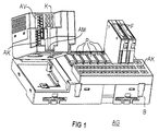
- the automation device AG at least exists from a basic module B, one with this electrically and mechanically detachably connectable head module K and at least one can be connected to the base module B electrically and mechanically detachably Function module F.
- the base module B also has external contacts A, which Connecting external devices, especially the actuators mentioned or sensors, for controlling and / or monitoring the enable technical process. Likewise, that points Head module K external contacts for connecting a power supply and / or for communicative connection with others electrical devices, which, however, cannot be seen in the FIG are.
- the function or electronics module F is on a receiving position P of the base module B.
- the base module B has a large number in the exemplary embodiment of recording positions P for recording one functional module each F on.
- the function module F itself has no external contacts but is in a capsule-shaped housing included, from which the contact means to the electrically conductive Contact with appropriate counter contact means of the base module B protrude.
- the head module K is also encapsulated in a housing, the openings for contacting the external contacts or openings for a contact means for contacting the corresponding one Has contact means of the base module B.
- the head module K enables permanent wiring and is simple solvable. Through a uniform interface, head modules K for different bus systems for communicative purposes Connect with other electrical devices become. Since the head module K does not contain any peripheral electronics, there is a favorable structure in terms of separation Electronics and peripherals, and thus better cooling and better EMC resistance.
- the present invention can be summarized as follows describe: It is a fieldbus controlled automation device AG to control and / or monitor the technical Process with a basic module B, a head module K with external contacts and at least one function module F without external contacts specified, the head module K or the functional module F electrically contactable with the base module B. is.
Landscapes
- Engineering & Computer Science (AREA)
- Automation & Control Theory (AREA)
- Microelectronics & Electronic Packaging (AREA)
- Physics & Mathematics (AREA)
- General Physics & Mathematics (AREA)
- Programmable Controllers (AREA)
- Paper (AREA)
- Control Of Eletrric Generators (AREA)
- Electrotherapy Devices (AREA)
- Details Of Connecting Devices For Male And Female Coupling (AREA)
- Connections Arranged To Contact A Plurality Of Conductors (AREA)
- Testing And Monitoring For Control Systems (AREA)
Abstract
Feldbusgesteuertes Automatisierungsgerät (AG) zur Steuerung
und/oder Überwachung eines technischen Prozesses mit einem
Basismodul (B), einem Kopfmodul (K) mit Außenkontakten und
mindestens einem Funktionsmodul (F) ohne Außenkontakte, wobei
das Kopfmodul (K) bzw. das Funktionsmodul (F) mit dem Basismodul
(B) elektrisch leitend kontaktierbar ist, wobei die Außenkontakte
das Kopfmoduls (K) zum Anschließen einer Spannungsversorgung
und/oder zum kommunikativen Verbinden mit
weiteren elektrischen Geräten vorgesehen sind und wobei das
Kopfmodul (K) zur Ansteuerung des mindestens einen Funktionsmoduls
(F) wirksam ist, wobei das Basismodul (B) Außenkontakte
zum Anschließen externer Geräte - insbesondere Aktoren
oder Sensoren zur Steuerung und/oder Überwachung des technischen
Prozesses - aufweist, die einem Funktionsmodul (F)
räumlich zugeordnet sind und mit diesem elektrisch leitend
verbunden sind.

Description
Die vorliegende Erfindung betrifft ein feldbusgesteuertes Automatisierungsgerät zur Steuerung und/oder Überwachung eines technischen Prozesses.The present invention relates to a fieldbus-controlled automation device to control and / or monitor a technical process.
Bei feldbusgesteuerten Automatisierungsgeräten sind sowohl kompakte als auch modulare Aufbauformen bekannt. Das Problem der stehenden Verdrahtung (schnelles und sicheres Auswechseln von Baugruppen bei Defekten oder Um- bzw. Nachrüstungen ohne die Notwendigkeit des Lösens von Drähten) ist bei kompakten Bauformen z.B. dadurch gelöst, daß die Baugruppen aus zwei Komponenten aufgebaut werden, einem festen Teil, der die Verdrahtung trägt, und einem wechselbaren Elektronikmodul.With fieldbus-controlled automation devices, both compact as well as modular designs known. The problem the permanent wiring (quick and safe replacement of modules in the event of defects or retrofitting or retrofitting without the need to disconnect wires) is compact Designs e.g. solved in that the assemblies of two Components are built, a fixed part, which is the wiring carries, and an exchangeable electronic module.
Bei modularen kanalgranularen Aufbauformen sind die Klemmen Bestandteil des einzelnen Funktionsmoduls, so daß beim Auswechseln eines Funktionsmoduls die an den Klemmen aufgelegten Kabel gelöst werden müssen, so daß eine stehende Verdrahtung nicht gegeben ist.In the case of modular channel-granular designs, the terminals are Part of the individual function module, so that when replacing of a function module the ones connected to the terminals Cables must be disconnected so that there is a permanent wiring is not given.
Die Aufgabe der vorliegenden Erfindung besteht daher darin, ein feldbusgesteuertes Automatisierungsgerät anzugeben, daß sowohl kompakt als auch kanalgranular aufgebaut werden kann.The object of the present invention is therefore to a fieldbus controlled automation device to indicate that can be built both compact and granular.
Diese Aufgabe wird mit einem feldbusgesteuerten Automatisierungsgerät der oben genannten Art mit einem Basismodul, einem Kopfmodul mit Außenkontakten und mindestens einem Funktionsmodul ohne Außenkontakte, wobei das Kopfmodul bzw. das Funktionsmodul mit dem Basismodul elektrisch leitend kontaktierbar ist, dadurch gelöst, daß die Außenkontakte des Kopfmoduls zum Anschließen einer Spannungsversorgung und/oder zum kommunikativen Verbinden mit weiteren elektrischen Geräten vorgesehen sind, daß das Kopfmodul zur Ansteuerung des mindestens einen Funktionsmoduls wirksam ist und daß das Basismodul Außenkontakte zum Anschließen externer Geräte - insbesondere Aktoren oder Sensoren zur Steuerung und /oder des technischen Prozesses - aufweist, die einem Funktionsmodul räumlich zugeordnet sind und mit diesem elektrisch leitend verbunden sind.This task is accomplished with a fieldbus controlled automation device of the type mentioned above with a basic module, a Head module with external contacts and at least one function module without external contacts, the head module or the function module contactable with the base module is solved in that the external contacts of the head module for connecting a power supply and / or for communicative purposes Connect to other electrical devices provided are that the head module to control the at least a functional module is effective and that the base module external contacts for connecting external devices - in particular Actuators or sensors for control and / or technical Process - has that spatially assigned to a functional module are and are connected to this electrically conductive.
Wenn das Basismodul Aufnahmepositionen zur Aufnahme des mindestens einem Funktionsmoduls aufweist, die eine bündige Anordnung benachbarter Funktionsmodule ermöglichen, ist eine besonders kompakte Bauform des Automatisierungsgerätes einerseits und eine gegenseitige Stabilisierung der jeweils benachbarten Funktionsmodule andererseits ermöglicht.If the base module has recording positions for recording the minimum a functional module that has a flush arrangement Enabling neighboring function modules is one particularly compact design of the automation device on the one hand and a mutual stabilization of the neighboring ones Function modules on the other hand.
Wenn die Außenkontakte des Kopfmuduls räumlich zueinander derart angeordnet sind, daß sich beim Kontaktieren der Außenkontakte ein konstruktionsbedingt zwangsweiser Handlungsablauf ergibt, ist ein Kontaktieren des Kopfmoduls nur in einer definierte Verhältnisse nach sich ziehenden Weise möglich. So kann z.B. der Außenkontakt für den Masse- und/oder Schirmanschluß nur kontaktiert werden, bevor die Außenkontakte für die Versorgungsspannung und die kommunikative Verbindung kontaktiert sind.If the external contacts of the head module are spatially related to each other are arranged so that when contacting the external contacts a compulsory course of action due to the design results in contacting the head module in only one defined conditions possible in a dragging manner. So can e.g. the external contact for the ground and / or shield connection only be contacted before the external contacts for the supply voltage and the communicative connection contacted are.
Wenn darüber hinaus ein elektrisches bzw. mechanisches Kontaktieren bzw. Dekontaktieren des Kopfmoduls mit dem Basismodul nur unter Einhaltung des konstruktionsbedingt zwangsweisen Handlungsablaufs beim Kontaktieren bzw. Dekonaktieren der Außenanschlüsse des Kopfmoduls möglich ist, ist z.B. sichergestellt, daß das Kopfmodul nur in spannungslosem Zustand vom Basismodul gelöst wird.If there is also an electrical or mechanical contact or decontacting the head module with the base module only in compliance with the compulsory design Sequence of actions when contacting or deconacting the External connections of the head module is possible, e.g. ensured that the head module is only in a de-energized state from Base module is solved.
Auf diese Weise läßt sich ebenfalls ein in bezug auf die kommunikative Verbindung, einen Bus, rückwirkungsfreies Zu- und Abschalten bestimmter Busteilnehmer erreichen, denn vor dem Abschalten des Busteilnehmers, des Kopfmoduls, ist erfindungsgemäß zwangsweise das Dekontaktieren des Außenanschlusses zur kommunikativen Verbindung erforderlich. Auswirkungen auf den derart abgetrennten Bus die ansonsten z.B. durch das Abschalten der Versorgungsspannung oder durch das Dekontaktieren des Kopfmoduls von dem Basismodul hervorgerufen werden könnten, sind auf diese Weise ausgeschlossen.In this way one can also relate to the communicative Connection, a bus, non-reactive access and Switch off certain bus participants, because before Switching off the bus subscriber, the head module, is according to the invention forcibly uncontacting the external connection required for communicative connection. Impact on the bus separated in this way, the e.g. by the Switching off the supply voltage or by decontacting of the head module are caused by the base module could be excluded in this way.
Ein Ausführungsbeispiel der Erfindung wird nachstehend anhand der Zeichnung näher erläutert. Dabei zeigen:
- FIG 1
- ein feldbusgesteuertes Automatisierungsgerät und
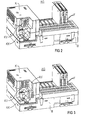
- FIGen 2 bis 5
- den konstruktionsbedingt zwangsweisen Handlungsablauf beim Kontaktieren und Dekontaktieren der Außenanschlüsse des Kopfmoduls.
- FIG. 1
- a fieldbus controlled automation device and
- FIGS. 2 to 5
- the design-related inevitable course of action when contacting and de-contacting the external connections of the head module.
Gemäß FIG 1 besteht das Automatisierungsgerät AG zumindest aus einem Basismodul B, einem mit diesem elektrisch und mechanisch lösbar verbindbaren Kopfmodul K und mindestens einem mit dem Basismodul B elektrisch und mechanisch lösbar verbindbaren Funktionsmodul F.According to FIG. 1, the automation device AG at least exists from a basic module B, one with this electrically and mechanically detachably connectable head module K and at least one can be connected to the base module B electrically and mechanically detachably Function module F.
Das Basismodul B weist weiterhin Außenkontakte A auf, die ein Anschließen externer Geräte, insbesondere der genannten Aktoren oder Sensoren, zur Steuerung und/oder Überwachung des technischen Prozesses ermöglichen. Gleichfalls weist das Kopfmodul K Außenkontakte zum Anschließen einer Spannungsversorgung und/oder zum kommunikativen Verbinden mit weiteren elektrischen Geräten auf, die jedoch in der FIG nicht ersichtlich sind. Das Funktions- oder Elektronikmodul F ist an einer Aufnahmeposition P des Basismoduls B angeordnet.The base module B also has external contacts A, which Connecting external devices, especially the actuators mentioned or sensors, for controlling and / or monitoring the enable technical process. Likewise, that points Head module K external contacts for connecting a power supply and / or for communicative connection with others electrical devices, which, however, cannot be seen in the FIG are. The function or electronics module F is on a receiving position P of the base module B.
Das Basismodul B weist im Ausführungsbeispiel eine Vielzahl von Aufnahmepositonen P zur Aufnahme jeweils eines Funktionsmoduls F auf. Das Funktionsmodul F weist selbst keine Außenkontakte auf, sondern ist in einem kapselförmigen Gehäuse eingeschlossen, aus dem die Kontaktmittel zum elektrisch leitenden Kontaktieren mit entsprechenden Gegenkontaktmitteln des Basismoduls B herausragen. The base module B has a large number in the exemplary embodiment of recording positions P for recording one functional module each F on. The function module F itself has no external contacts but is in a capsule-shaped housing included, from which the contact means to the electrically conductive Contact with appropriate counter contact means of the base module B protrude.
Auch das Kopfmodul K ist in einem Gehäuse gekapselt, das Öffnungen zum Kontaktieren der Außenkontakte bzw. Öffnungen für ein Kontaktmittel zum Kontaktieren mit dem entsprechenden Kontaktmitteln des Basismoduls B aufweist. Das Kopfmodul K ermöglicht damit eine stehende Verdrahtung und ist einfach lösbar. Durch eine einheitliche Schnittstelle können Kopfmodule K für jeweils unterschiedliche Bussysteme zum kommunikativen Verbinden mit anderen elektrischen Geräten aufgesteckt werden. Da das Kopfmodul K keine Peripherieelektronik enthält, ergibt sich eine günstige Struktur bezüglich der Trennung Elektronik und Peripherie, und damit eine bessere Entwärmung und bessere EMV-Festigkeit.The head module K is also encapsulated in a housing, the openings for contacting the external contacts or openings for a contact means for contacting the corresponding one Has contact means of the base module B. The head module K enables permanent wiring and is simple solvable. Through a uniform interface, head modules K for different bus systems for communicative purposes Connect with other electrical devices become. Since the head module K does not contain any peripheral electronics, there is a favorable structure in terms of separation Electronics and peripherals, and thus better cooling and better EMC resistance.
Im Ausführungsbeispiel sind die Außenkontakte AV, AK,AM des Kopfmoduls K zum Anschluß der Versorgungsspannung AV und der Buskommunikation AK so angeordnet, daß die mechanische Verbindung zum Basismodul B durch die mit den Außenkontakten AV, AK, AM kontaktierten Kontaktelementen KV, KK, KM verdeckt wird. Dies erfordert bei Montage bzw. Demontage eine bestimmte, durch die räumliche Anordnung der Kontakte AV, AK, AM festgelegte Reihenfolge beim Herstellen bzw. Lösen der elektrischen und mechanischen Verbindungen. Der damit bewirkte konstruktionsbedingt zwangsweise Handlungsablauf beim Kontaktieren und Dekontaktieren der Außenanschlüsse AV, AK, AM des Kopfmoduls ist in den FIGen 2 bis 5 dargestellt.In the exemplary embodiment, the external contacts AV, AK, AM of Head module K for connecting the supply voltage AV and the Bus communication AK arranged so that the mechanical connection to the base module B by means of the AV external contacts, AK, AM contacted contact elements KV, KK, KM hidden becomes. This requires a certain, during assembly or disassembly due to the spatial arrangement of the contacts AV, AK, AM fixed order when manufacturing or releasing the electrical and mechanical connections. The one brought about Due to the design, the course of action when contacting is compulsory and decontacting the external connections AV, AK, AM of the Head module is shown in FIGS. 2 to 5.
Damit wird eine hohe Sicherheit bei der Inbetriebnahme bzw. Deinstallation des gesamten Automatisierungsgerätes AG erreicht, da die Reihenfolge der Arbeitschritte unabhängig von der eventuellen Beachtung im Handbuch dokumentierter Arbeitsschritte ist.This ensures a high level of security during commissioning and Uninstallation of the entire automation device AG achieved, because the order of the work steps is independent of the possible observance of the work steps documented in the manual is.
Für das Lösen das Kopfmoduls K ergeben sich konstruktionsbeding
zwangsweise die nachfolgenden Arbeitsschritte:
Das Montieren erfolgt analog in umgekehrter Reihenfolge. Dabei führt das Herstellen der kommunikativen Verbindung AK, KK vor dem Anschließen der Versorgungsspannung AV, KV dazu, daß zwangsläufig ein definierter Hochlauf der Baugruppe am Bussystem erfolgt. Das Automatisierungsgerät AG nimmt seine Funktion erst mit dem sicheren Anstehen der jeweiligen Versorgungsspannungen auf. Zu diesem Zeitpunkt herrschen aufgrund der konstruktionsbedingt zwangsweise bereits zuvor erfolgten kommunikativen Verbindung auf dem Bus - der kommunikativen Verbindung - bereits eingeschwungene Zustände. Ein vergleichbares Verhalten ist gegenwärtig bei marktüblichen Automatisierungsgeräten nur über ein speziell dafür vorgesehenes Schaltelement auf der Baugruppe, das ein zentrales Ab/Zu-Schalten der Logikspannung auslöst, oder einen Softwarereset möglich.Installation is carried out in the reverse order. Here leads the establishment of the communicative connection AK, KK before connecting the supply voltage AV, KV to that inevitably a defined startup of the module on the bus system he follows. The automation device AG takes over its function only with the safe supply of the respective supply voltages on. Prevail at this time which, due to the design, had already taken place previously communicative connection on the bus - the communicative Connection - steady state. A comparable one Behavior is currently common with automation devices on the market only through a specially designed one Switching element on the module, which is a central switching off / on the logic voltage, or a software reset possible.
Zusammenfassend läßt sich die vorliegende Erfindung wie folgt beschreiben: Es wird ein feldbusgesteuertes Automatisierungsgerät AG zur Steuerung und/oder Überwachung des technischen Prozesses mit einem Basismodul B, einem Kopfmodul K mit Außenkontakten und mindestens einem Funktionsmodul F ohne Außenkontakte angegeben, wobei das Kopfmodul K bzw. das Funktionsmodul F mit dem Basismodul B elektrisch leitend kontaktierbar ist. Damit steht ein feldbusgesteuertes Automatisierungsgerät AG zur Verfügung, welches sowohl kompakt als auch kanalgranular aufgebaut werden kann und dabei jeweils eine stehende Verdrahtung bietet, so daß das Auswechseln einzelner Komponenten jederzeit leicht und effektiv möglich ist.In summary, the present invention can be summarized as follows describe: It is a fieldbus controlled automation device AG to control and / or monitor the technical Process with a basic module B, a head module K with external contacts and at least one function module F without external contacts specified, the head module K or the functional module F electrically contactable with the base module B. is. This means that there is a fieldbus-controlled automation device AG available, which is both compact and can be built up in granular form and one at a time offers standing wiring, so that the replacement of individual Components easily and effectively at any time.
Claims (4)
Applications Claiming Priority (2)
| Application Number | Priority Date | Filing Date | Title |
|---|---|---|---|
| DE29716575U | 1997-09-15 | ||
| DE29716575U DE29716575U1 (en) | 1997-09-15 | 1997-09-15 | Fieldbus controlled automation device |
Publications (3)
| Publication Number | Publication Date |
|---|---|
| EP0902346A2 true EP0902346A2 (en) | 1999-03-17 |
| EP0902346A3 EP0902346A3 (en) | 2000-07-19 |
| EP0902346B1 EP0902346B1 (en) | 2002-12-04 |
Family
ID=8046031
Family Applications (1)
| Application Number | Title | Priority Date | Filing Date |
|---|---|---|---|
| EP98116594A Expired - Lifetime EP0902346B1 (en) | 1997-09-15 | 1998-09-02 | Modular field bus controlled automation device |
Country Status (4)
| Country | Link |
|---|---|
| EP (1) | EP0902346B1 (en) |
| AT (1) | ATE229195T1 (en) |
| DE (2) | DE29716575U1 (en) |
| ES (1) | ES2189055T3 (en) |
Cited By (2)
| Publication number | Priority date | Publication date | Assignee | Title |
|---|---|---|---|---|
| WO2001031688A3 (en) * | 1999-10-29 | 2001-09-20 | Siemens Ag | Method for exchanging a sub-assembly frame using an auxiliary sub-assembly frame |
| WO2018219400A1 (en) * | 2017-05-31 | 2018-12-06 | Robodev Gmbh | Field device of modular construction |
Families Citing this family (7)
| Publication number | Priority date | Publication date | Assignee | Title |
|---|---|---|---|---|
| DE19816170C5 (en) * | 1998-04-09 | 2004-09-23 | Sew-Eurodrive Gmbh & Co | control module |
| DE10135980C1 (en) * | 2001-07-24 | 2003-04-24 | Abb Patent Gmbh | Arrangement for connection of decentralized local field devices to remote central station, has input/output units with system- and field-side communications interfaces in same plug plane |
| DE102004056243A1 (en) * | 2004-11-22 | 2006-05-24 | Abb Patent Gmbh | Modular automation system |
| CN100519101C (en) * | 2005-11-29 | 2009-07-29 | 精工爱普生株式会社 | Robot control device and robot system |
| JP4232796B2 (en) | 2005-11-29 | 2009-03-04 | セイコーエプソン株式会社 | Robot control apparatus and robot system |
| DE102009046552B4 (en) * | 2009-11-10 | 2014-03-06 | EDS Systemtechnik Gesellschaft für elektronische Datenverarbeitungsanlagen mbH | Process data computer |
| JP5983696B2 (en) * | 2014-01-29 | 2016-09-06 | 横河電機株式会社 | Electronics |
Family Cites Families (3)
| Publication number | Priority date | Publication date | Assignee | Title |
|---|---|---|---|---|
| DE3429020A1 (en) * | 1984-08-07 | 1986-02-20 | Ifm Electronic Gmbh, 4300 Essen | PROGRAMMABLE CONTROL |
| DE4438806C1 (en) * | 1994-10-31 | 1996-03-21 | Weidmueller Interface | Modular control system with bus conductor |
| DE4440102C1 (en) * | 1994-11-10 | 1996-05-15 | Weidmueller Interface | Modular control system with integrated fieldbus connection |
-
1997
- 1997-09-15 DE DE29716575U patent/DE29716575U1/en not_active Expired - Lifetime
-
1998
- 1998-09-02 AT AT98116594T patent/ATE229195T1/en not_active IP Right Cessation
- 1998-09-02 EP EP98116594A patent/EP0902346B1/en not_active Expired - Lifetime
- 1998-09-02 ES ES98116594T patent/ES2189055T3/en not_active Expired - Lifetime
- 1998-09-02 DE DE59806506T patent/DE59806506D1/en not_active Expired - Lifetime
Cited By (4)
| Publication number | Priority date | Publication date | Assignee | Title |
|---|---|---|---|---|
| WO2001031688A3 (en) * | 1999-10-29 | 2001-09-20 | Siemens Ag | Method for exchanging a sub-assembly frame using an auxiliary sub-assembly frame |
| WO2018219400A1 (en) * | 2017-05-31 | 2018-12-06 | Robodev Gmbh | Field device of modular construction |
| CN110651536A (en) * | 2017-05-31 | 2020-01-03 | 罗博德夫公司 | Field devices with modular construction |
| US10921867B2 (en) | 2017-05-31 | 2021-02-16 | Robodev Gmbh | Field device of modular construction |
Also Published As
| Publication number | Publication date |
|---|---|
| ATE229195T1 (en) | 2002-12-15 |
| EP0902346B1 (en) | 2002-12-04 |
| EP0902346A3 (en) | 2000-07-19 |
| ES2189055T3 (en) | 2003-07-01 |
| DE59806506D1 (en) | 2003-01-16 |
| DE29716575U1 (en) | 1997-11-13 |
Similar Documents
| Publication | Publication Date | Title |
|---|---|---|
| EP0709932B1 (en) | Modular control installation with bus, e.g. for automation of buildings | |
| EP0709933B1 (en) | Modular control installation with bus | |
| EP0314949B1 (en) | Electrical function group for a vehicle | |
| EP1029390B1 (en) | Communicating switch gear unit | |
| DE4440102C1 (en) | Modular control system with integrated fieldbus connection | |
| EP0710064B1 (en) | Field bus connection module | |
| WO1998026640A2 (en) | Modular electric apparatus | |
| EP1917672B1 (en) | Connecting system comprising an electromagnetic switchgear, especially contactor, and a connector | |
| EP0902346B1 (en) | Modular field bus controlled automation device | |
| EP0943165B1 (en) | Switch cupboard | |
| DE4323440A1 (en) | Electronic device, in particular automation device | |
| EP0493740B1 (en) | Connection module for a distributing equipment, especially for the main distributing frame of telecommunication arrangements | |
| EP1474853B1 (en) | Electric power circuit breaker comprising a connection device for auxiliary current circuits | |
| DE202022105775U1 (en) | Modular electronic fuses and fuse box | |
| EP0769679A1 (en) | Mountable multi-channel writer | |
| EP3660603B1 (en) | Bus-capable functional modules that can be connected to one another | |
| DE4013815C2 (en) | Control circuit for machines | |
| EP0888707B1 (en) | Module with a circuit arrangement | |
| DE4316291A1 (en) | Electronic device, in particular automation device | |
| EP1282348B1 (en) | Connecting device for local networks | |
| DE102006056255B4 (en) | Supply module for servomotors, control cabinet arrangement and electrical system | |
| EP0593995A1 (en) | Device and method for supplying current consuming appliances with power current | |
| EP1808878B1 (en) | Electrical device with load circuit switching in an explosive environment | |
| EP1357645A1 (en) | Intelligent connector for a data bus | |
| DE19921970A1 (en) | Adapter arrangement for connecting components to terminal box or cabinet, has common conductor with plus pole integrated for use for all sensors and connected through to all sensors in common with minus pole conductor and earth conductor |
Legal Events
| Date | Code | Title | Description |
|---|---|---|---|
| PUAI | Public reference made under article 153(3) epc to a published international application that has entered the european phase |
Free format text: ORIGINAL CODE: 0009012 |
|
| AK | Designated contracting states |
Kind code of ref document: A2 Designated state(s): AT CH DE ES FR GB LI |
|
| AX | Request for extension of the european patent |
Free format text: AL;LT;LV;MK;RO;SI |
|
| PUAL | Search report despatched |
Free format text: ORIGINAL CODE: 0009013 |
|
| AK | Designated contracting states |
Kind code of ref document: A3 Designated state(s): AT BE CH CY DE DK ES FI FR GB GR IE IT LI LU MC NL PT SE |
|
| AX | Request for extension of the european patent |
Free format text: AL;LT;LV;MK;RO;SI |
|
| RIC1 | Information provided on ipc code assigned before grant |
Free format text: 7G 05B 19/418 A, 7H 05K 7/14 B |
|
| 17P | Request for examination filed |
Effective date: 20010118 |
|
| AKX | Designation fees paid | ||
| RBV | Designated contracting states (corrected) |
Designated state(s): AT CH DE ES FR GB LI |
|
| REG | Reference to a national code |
Ref country code: DE Ref legal event code: 8566 |
|
| 17Q | First examination report despatched |
Effective date: 20010711 |
|
| GRAG | Despatch of communication of intention to grant |
Free format text: ORIGINAL CODE: EPIDOS AGRA |
|
| GRAG | Despatch of communication of intention to grant |
Free format text: ORIGINAL CODE: EPIDOS AGRA |
|
| GRAH | Despatch of communication of intention to grant a patent |
Free format text: ORIGINAL CODE: EPIDOS IGRA |
|
| GRAH | Despatch of communication of intention to grant a patent |
Free format text: ORIGINAL CODE: EPIDOS IGRA |
|
| GRAA | (expected) grant |
Free format text: ORIGINAL CODE: 0009210 |
|
| AK | Designated contracting states |
Kind code of ref document: B1 Designated state(s): AT CH DE ES FR GB LI |
|
| REF | Corresponds to: |
Ref document number: 229195 Country of ref document: AT Date of ref document: 20021215 Kind code of ref document: T |
|
| REG | Reference to a national code |
Ref country code: GB Ref legal event code: FG4D Free format text: NOT ENGLISH |
|
| REG | Reference to a national code |
Ref country code: CH Ref legal event code: NV Representative=s name: SIEMENS SCHWEIZ AG Ref country code: CH Ref legal event code: EP |
|
| GBT | Gb: translation of ep patent filed (gb section 77(6)(a)/1977) |
Effective date: 20021204 |
|
| REF | Corresponds to: |
Ref document number: 59806506 Country of ref document: DE Date of ref document: 20030116 |
|
| REG | Reference to a national code |
Ref country code: ES Ref legal event code: FG2A Ref document number: 2189055 Country of ref document: ES Kind code of ref document: T3 |
|
| ET | Fr: translation filed | ||
| PLBE | No opposition filed within time limit |
Free format text: ORIGINAL CODE: 0009261 |
|
| STAA | Information on the status of an ep patent application or granted ep patent |
Free format text: STATUS: NO OPPOSITION FILED WITHIN TIME LIMIT |
|
| 26N | No opposition filed |
Effective date: 20030905 |
|
| PGFP | Annual fee paid to national office [announced via postgrant information from national office to epo] |
Ref country code: CH Payment date: 20031203 Year of fee payment: 6 |
|
| PGFP | Annual fee paid to national office [announced via postgrant information from national office to epo] |
Ref country code: AT Payment date: 20040831 Year of fee payment: 7 |
|
| PGFP | Annual fee paid to national office [announced via postgrant information from national office to epo] |
Ref country code: ES Payment date: 20040915 Year of fee payment: 7 |
|
| PG25 | Lapsed in a contracting state [announced via postgrant information from national office to epo] |
Ref country code: LI Free format text: LAPSE BECAUSE OF NON-PAYMENT OF DUE FEES Effective date: 20040930 Ref country code: CH Free format text: LAPSE BECAUSE OF NON-PAYMENT OF DUE FEES Effective date: 20040930 |
|
| REG | Reference to a national code |
Ref country code: CH Ref legal event code: PL |
|
| PG25 | Lapsed in a contracting state [announced via postgrant information from national office to epo] |
Ref country code: AT Free format text: LAPSE BECAUSE OF NON-PAYMENT OF DUE FEES Effective date: 20050902 |
|
| PG25 | Lapsed in a contracting state [announced via postgrant information from national office to epo] |
Ref country code: ES Free format text: LAPSE BECAUSE OF NON-PAYMENT OF DUE FEES Effective date: 20050903 |
|
| REG | Reference to a national code |
Ref country code: ES Ref legal event code: FD2A Effective date: 20050903 |
|
| PGFP | Annual fee paid to national office [announced via postgrant information from national office to epo] |
Ref country code: DE Payment date: 20101119 Year of fee payment: 13 |
|
| PGFP | Annual fee paid to national office [announced via postgrant information from national office to epo] |
Ref country code: GB Payment date: 20110915 Year of fee payment: 14 Ref country code: FR Payment date: 20111005 Year of fee payment: 14 |
|
| GBPC | Gb: european patent ceased through non-payment of renewal fee |
Effective date: 20120902 |
|
| REG | Reference to a national code |
Ref country code: FR Ref legal event code: ST Effective date: 20130531 |
|
| PG25 | Lapsed in a contracting state [announced via postgrant information from national office to epo] |
Ref country code: GB Free format text: LAPSE BECAUSE OF NON-PAYMENT OF DUE FEES Effective date: 20120902 Ref country code: DE Free format text: LAPSE BECAUSE OF NON-PAYMENT OF DUE FEES Effective date: 20130403 |
|
| PG25 | Lapsed in a contracting state [announced via postgrant information from national office to epo] |
Ref country code: FR Free format text: LAPSE BECAUSE OF NON-PAYMENT OF DUE FEES Effective date: 20121001 |
|
| REG | Reference to a national code |
Ref country code: DE Ref legal event code: R119 Ref document number: 59806506 Country of ref document: DE Effective date: 20130403 |