EP0902228B1 - Rohrschnellkupplung - Google Patents
Rohrschnellkupplung Download PDFInfo
- Publication number
- EP0902228B1 EP0902228B1 EP98116173A EP98116173A EP0902228B1 EP 0902228 B1 EP0902228 B1 EP 0902228B1 EP 98116173 A EP98116173 A EP 98116173A EP 98116173 A EP98116173 A EP 98116173A EP 0902228 B1 EP0902228 B1 EP 0902228B1
- Authority
- EP
- European Patent Office
- Prior art keywords
- pipe
- cage
- annular
- pipes
- thickening
- Prior art date
- Legal status (The legal status is an assumption and is not a legal conclusion. Google has not performed a legal analysis and makes no representation as to the accuracy of the status listed.)
- Expired - Lifetime
Links
Images
Classifications
-
- F—MECHANICAL ENGINEERING; LIGHTING; HEATING; WEAPONS; BLASTING
- F16—ENGINEERING ELEMENTS AND UNITS; GENERAL MEASURES FOR PRODUCING AND MAINTAINING EFFECTIVE FUNCTIONING OF MACHINES OR INSTALLATIONS; THERMAL INSULATION IN GENERAL
- F16L—PIPES; JOINTS OR FITTINGS FOR PIPES; SUPPORTS FOR PIPES, CABLES OR PROTECTIVE TUBING; MEANS FOR THERMAL INSULATION IN GENERAL
- F16L37/00—Couplings of the quick-acting type
- F16L37/50—Couplings of the quick-acting type adjustable; allowing movement of the parts joined
- F16L37/505—Couplings of the quick-acting type adjustable; allowing movement of the parts joined allowing substantial longitudinal adjustment or movement
-
- F—MECHANICAL ENGINEERING; LIGHTING; HEATING; WEAPONS; BLASTING
- F16—ENGINEERING ELEMENTS AND UNITS; GENERAL MEASURES FOR PRODUCING AND MAINTAINING EFFECTIVE FUNCTIONING OF MACHINES OR INSTALLATIONS; THERMAL INSULATION IN GENERAL
- F16L—PIPES; JOINTS OR FITTINGS FOR PIPES; SUPPORTS FOR PIPES, CABLES OR PROTECTIVE TUBING; MEANS FOR THERMAL INSULATION IN GENERAL
- F16L27/00—Adjustable joints, Joints allowing movement
- F16L27/12—Adjustable joints, Joints allowing movement allowing substantial longitudinal adjustment or movement
Definitions
- the invention relates to a quick pipe coupling in the preamble of the claim 1 explained Art.
- DE 26 52 207 C3 is a quick pipe coupling for tight-fitting connection two pipes, with one arranged on the outside of the one pipe Cage with an annular coil spring arranged therein known serves, in the case of axially pushed tubes, the second tube at a flare hold.
- the seal between the two nested tubes takes place via an arrangement of O-rings and by the in the known Quick pipe coupling axially fixed to a pipe cage are the two pipes also secured against unintentional axial pulling apart.
- Quick pipe couplings of this type are increasingly used in motor vehicles for connecting the various pipes for the refrigerant of air conditioning systems used and accordingly had to date with a variety of Vehicle models due to the required adaptation to the installation space of corresponding pipe parts with the corresponding pipe quick couplings be stocked.
- the object of the invention is based on the observation that a variety of such pipe components to be stored are only available in small length dimensions differ from each other and that the arrangement of these pipe components in the motor vehicle usually done in such a way that after assembly with the required Length compensation the pipe components are set such that an unintentional axial pull apart is hardly possible. A complete pull apart after reaching the maximum length compensation by the thickening of the entering pipe is reduced.
- the object underlying the invention is therefore the known To convert pipe quick coupling so that with their help a considerable length compensation is possible.
- this object is achieved by a quick pipe coupling the type explained in the preamble of the claim in the characterizing part of Features indicated features.
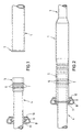
- connection of two pipes consists of a receiving pipe 1, which is on his free end is provided with a flare 2, possibly the tube 1 in its further course be provided with a constriction 3.
- the incoming tube 4 is provided with a thickening 5 at its free end, in the receiving grooves 6, mostly produced by a special upsetting process, are arranged for conventional O-ring seals 7.
- the outer diameter of the thickening 5 fits into the inner diameter with a sliding fit of the receiving tube 1 into it.
- a cage 8 is arranged on the tube 4, which has an annular shape in a known manner Coil spring 9 takes.
- the ring-shaped cage 8 has an inlet opening 10 on whose diameter the unimpeded entry of the flare 2 of receiving tube 1 allows.
- the other diameter 11 of the annular Cage 8 is only slightly larger than the outer diameter of the tube 4 and is loosely arranged on this.
- the thickening 5 in different axial positions (one position is in dashed lines and a possible other position is in dash-dot lines indicated.), are located within the receiving tube 1 and by sliding the annular cage 8 on the flare 2 of the tube 1 is so far a locking of the two tubes 1 and 4 is achieved by the annular Cage 8 is inseparable from the outwardly widened annular coil spring 9 (without special tools) is connected to pipe 1. It is also a complete one Pull apart by coming into contact with the cage 8 on the thickening 5 safely prevented.
Description
- Fig. 1
- eine Ansicht der beiden Rohrenden vor dem axialen Zusammenfügen und
- Fig. 2
- zeigt die miteinander verbundenen Rohrenden bei eingerasteter ringförmiger Schraubenfeder.
Claims (1)
- Rohrschnellkupplung zum dichtschließenden Verbinden zweier Rohre, enthaltenddadurch gekennzeichnet, dass der minimale Durchmesser des ringförmigen Käfigs (8) so groß ist, dass der Käfig auf dem Außenumfang des zweiten Rohres (4) axial lose verschiebbar ist, jedoch nicht über die Verdickung (5) des zweiten Rohres passt.ein erstes Rohr (1) mit einer Aufbördelung (2) am Ende;ein zweites Rohr (4), welches axial in das erste Rohr (1) eingeschoben werden kann;einen an der Außenseite des zweiten Rohres (4) angeordneten ringförmigen Käfig (8), in dem eine ringförmige Schraubenfeder (9) angeordnet ist, die bei axial ineinandergeschobenen Rohren (1 und 4) über die Aufbördelung (2) rastet;eine Dichtungsanordnung in Form von Ringnuten (6) und O-Ring-Dichtungen (7), die in einer radial nach außen gerichteten Verdickung (5) des zweiten Rohres (4) vorgesehen ist;
Applications Claiming Priority (2)
| Application Number | Priority Date | Filing Date | Title |
|---|---|---|---|
| DE19740356 | 1997-09-13 | ||
| DE19740356A DE19740356C1 (de) | 1997-09-13 | 1997-09-13 | Rohrschnellkupplung |
Publications (2)
| Publication Number | Publication Date |
|---|---|
| EP0902228A1 EP0902228A1 (de) | 1999-03-17 |
| EP0902228B1 true EP0902228B1 (de) | 2002-08-14 |
Family
ID=7842287
Family Applications (1)
| Application Number | Title | Priority Date | Filing Date |
|---|---|---|---|
| EP98116173A Expired - Lifetime EP0902228B1 (de) | 1997-09-13 | 1998-08-27 | Rohrschnellkupplung |
Country Status (4)
| Country | Link |
|---|---|
| US (1) | US5951065A (de) |
| EP (1) | EP0902228B1 (de) |
| JP (1) | JPH11148586A (de) |
| DE (2) | DE19740356C1 (de) |
Families Citing this family (4)
| Publication number | Priority date | Publication date | Assignee | Title |
|---|---|---|---|---|
| DE19934185A1 (de) * | 1999-07-21 | 2001-01-25 | Siemens Ag | Optische Kopplungseinrichtung |
| US8464424B2 (en) * | 2010-11-01 | 2013-06-18 | Hans Martin Christensen | Automotive engine cooling pipe apparatus and method of use |
| JP6241359B2 (ja) * | 2014-04-15 | 2017-12-06 | 三菱電機株式会社 | 貯湯式給湯機及び管継手 |
| DE102015203851A1 (de) | 2015-03-04 | 2016-09-08 | Contitech Techno-Chemie Gmbh | Verbindungsanordnung |
Family Cites Families (11)
| Publication number | Priority date | Publication date | Assignee | Title |
|---|---|---|---|---|
| US4055359A (en) * | 1975-11-17 | 1977-10-25 | Ford Motor Company | Quick-connect tubular couplings |
| US4401326A (en) * | 1981-12-16 | 1983-08-30 | Ford Motor Company | Quick-connect tubular coupling |
| JPS5993589A (ja) * | 1982-11-17 | 1984-05-30 | 倉地 久治 | ホ−ス類の接続装置 |
| US4632434A (en) * | 1985-07-08 | 1986-12-30 | Murray Corporation | Coupling means for tubular members |
| GB2205137B (en) * | 1987-05-27 | 1991-07-24 | United Carr Ltd Trw | Device for preventing separation of spigot and socket connections |
| US5002314A (en) * | 1988-05-23 | 1991-03-26 | Smith Arthur W | Locking assembly for push-on fittings |
| US5301408A (en) * | 1992-03-31 | 1994-04-12 | R & B, Inc. | Garter spring coupling release tool |
| US5364131A (en) * | 1993-02-01 | 1994-11-15 | Ford Motor Company | Quick-connect tubular coupling |
| US5425558A (en) * | 1993-08-17 | 1995-06-20 | Handy & Harman Automotive Group, Inc. | Quick-connect coupling |
| DE19513058C2 (de) | 1995-04-07 | 1997-02-13 | Ford Werke Ag | Rohrverbindung |
| US5816626A (en) * | 1995-12-05 | 1998-10-06 | Ford Motor Company | Spring lock coupling |
-
1997
- 1997-09-13 DE DE19740356A patent/DE19740356C1/de not_active Expired - Fee Related
-
1998
- 1998-08-27 EP EP98116173A patent/EP0902228B1/de not_active Expired - Lifetime
- 1998-08-27 DE DE59805169T patent/DE59805169D1/de not_active Expired - Fee Related
- 1998-09-03 JP JP10267301A patent/JPH11148586A/ja active Pending
- 1998-09-14 US US09/152,317 patent/US5951065A/en not_active Expired - Fee Related
Also Published As
| Publication number | Publication date |
|---|---|
| DE59805169D1 (de) | 2002-09-19 |
| JPH11148586A (ja) | 1999-06-02 |
| US5951065A (en) | 1999-09-14 |
| EP0902228A1 (de) | 1999-03-17 |
| DE19740356C1 (de) | 1998-12-03 |
Similar Documents
| Publication | Publication Date | Title |
|---|---|---|
| DE3531926C2 (de) | ||
| EP1805447B1 (de) | Zugfeste steckkupplung | |
| DE19957946B4 (de) | Anschlußstutzen für einen Wärmeübertrager | |
| DE202007018700U1 (de) | Steckerteil einer Steckverbindungsanordnung sowie Steckverbindungsanordnung | |
| EP1070215A1 (de) | Vorrichtung zum verbinden eines rohrstutzens, rohrförmigen armaturenteils oder fittings mit einem rohr | |
| DE3811587A1 (de) | Verriegelungselement bei einer schnellkupplung zur verbindung von rohr- oder schlauchleitungen | |
| DE4307514C2 (de) | Verbinder für dünne Rohre | |
| DE2952468A1 (de) | Steckbare verbindungsvorrichtung mit schnappverschluss | |
| AT410706B (de) | Anschlussvorrichtung für ein kunststoffrohr | |
| EP0750150B1 (de) | Steckverbindung für den Anschluss von Rohr- und Schlauchleitungen | |
| DE19702289A1 (de) | Anordnung zur Verbindung von Rohren oder Schläuchen mit Armaturen oder Fittings | |
| DE3502424A1 (de) | Kaeltemittelkupplung, insbesondere fuer klimaanlagen von kraftfahrzeugen | |
| EP0902228B1 (de) | Rohrschnellkupplung | |
| DE10248986A1 (de) | Rohrverbindung und Verfahren zu ihrer Herstellung | |
| EP0319746A1 (de) | Vorrichtung zum gegenseitigen Verbinden von zwei Leitungen, insbesondere Kraftstoffleitungen | |
| DE19614684A1 (de) | Vorrichtung zur Verbindung von Rohren oder dergleichen rohrförmigen Armaturenteilen mit einer Armatur für fluide Medien | |
| EP2133615B2 (de) | Kupplungseinrichtung, insbesondere für eine Frischluftanlage | |
| DE3705610A1 (de) | Loesbare steckverbindung fuer rohrleitungen | |
| EP0811798A2 (de) | Steck-Kupplung | |
| DE69913082T2 (de) | Flüssigkeitskupplung mit abgestuften, synchronisierten Gewinden | |
| DD297499A5 (de) | Befestigung und befestigungsverfahren | |
| EP0222855B2 (de) | Verfahren zur herstellung eines schlauchnippels für hydraulisch belastete press- oder schraubarmaturen | |
| EP1126206B1 (de) | Pressverbindung für Rohre | |
| DE202011103941U1 (de) | Rohrverbinder | |
| DE3007509C2 (de) | Rohrkupplung |
Legal Events
| Date | Code | Title | Description |
|---|---|---|---|
| PUAI | Public reference made under article 153(3) epc to a published international application that has entered the european phase |
Free format text: ORIGINAL CODE: 0009012 |
|
| AK | Designated contracting states |
Kind code of ref document: A1 Designated state(s): DE FR GB |
|
| AX | Request for extension of the european patent |
Free format text: AL;LT;LV;MK;RO;SI |
|
| RIN1 | Information on inventor provided before grant (corrected) |
Inventor name: KOCK, CRISTOF Inventor name: BOEHME, DIETMAR Inventor name: ROESNER, THOMAS WILHELM |
|
| 17P | Request for examination filed |
Effective date: 19990917 |
|
| AKX | Designation fees paid |
Free format text: DE FR GB |
|
| 17Q | First examination report despatched |
Effective date: 20001227 |
|
| GRAG | Despatch of communication of intention to grant |
Free format text: ORIGINAL CODE: EPIDOS AGRA |
|
| GRAG | Despatch of communication of intention to grant |
Free format text: ORIGINAL CODE: EPIDOS AGRA |
|
| GRAH | Despatch of communication of intention to grant a patent |
Free format text: ORIGINAL CODE: EPIDOS IGRA |
|
| GRAH | Despatch of communication of intention to grant a patent |
Free format text: ORIGINAL CODE: EPIDOS IGRA |
|
| GRAA | (expected) grant |
Free format text: ORIGINAL CODE: 0009210 |
|
| AK | Designated contracting states |
Kind code of ref document: B1 Designated state(s): DE FR GB |
|
| REG | Reference to a national code |
Ref country code: GB Ref legal event code: FG4D Free format text: NOT ENGLISH |
|
| REF | Corresponds to: |
Ref document number: 59805169 Country of ref document: DE Date of ref document: 20020919 |
|
| GBT | Gb: translation of ep patent filed (gb section 77(6)(a)/1977) |
Effective date: 20020919 |
|
| PG25 | Lapsed in a contracting state [announced via postgrant information from national office to epo] |
Ref country code: GB Free format text: LAPSE BECAUSE OF NON-PAYMENT OF DUE FEES Effective date: 20021114 |
|
| ET | Fr: translation filed | ||
| PGFP | Annual fee paid to national office [announced via postgrant information from national office to epo] |
Ref country code: DE Payment date: 20030222 Year of fee payment: 5 |
|
| PLBE | No opposition filed within time limit |
Free format text: ORIGINAL CODE: 0009261 |
|
| STAA | Information on the status of an ep patent application or granted ep patent |
Free format text: STATUS: NO OPPOSITION FILED WITHIN TIME LIMIT |
|
| PG25 | Lapsed in a contracting state [announced via postgrant information from national office to epo] |
Ref country code: FR Free format text: LAPSE BECAUSE OF NON-PAYMENT OF DUE FEES Effective date: 20030630 |
|
| GBPC | Gb: european patent ceased through non-payment of renewal fee | ||
| 26N | No opposition filed |
Effective date: 20030515 |
|
| REG | Reference to a national code |
Ref country code: FR Ref legal event code: ST |
|
| PG25 | Lapsed in a contracting state [announced via postgrant information from national office to epo] |
Ref country code: DE Free format text: LAPSE BECAUSE OF NON-PAYMENT OF DUE FEES Effective date: 20040302 |
|
| PG25 | Lapsed in a contracting state [announced via postgrant information from national office to epo] |
Ref country code: FR Free format text: LAPSE BECAUSE OF NON-PAYMENT OF DUE FEES Effective date: 20020831 |