EP0902225A1 - Dispositif de traversée - Google Patents
Dispositif de traversée Download PDFInfo
- Publication number
- EP0902225A1 EP0902225A1 EP98117429A EP98117429A EP0902225A1 EP 0902225 A1 EP0902225 A1 EP 0902225A1 EP 98117429 A EP98117429 A EP 98117429A EP 98117429 A EP98117429 A EP 98117429A EP 0902225 A1 EP0902225 A1 EP 0902225A1
- Authority
- EP
- European Patent Office
- Prior art keywords
- line
- bushing device
- casing
- sealing
- support element
- Prior art date
- Legal status (The legal status is an assumption and is not a legal conclusion. Google has not performed a legal analysis and makes no representation as to the accuracy of the status listed.)
- Withdrawn
Links
Images


Classifications
-
- H—ELECTRICITY
- H02—GENERATION; CONVERSION OR DISTRIBUTION OF ELECTRIC POWER
- H02G—INSTALLATION OF ELECTRIC CABLES OR LINES, OR OF COMBINED OPTICAL AND ELECTRIC CABLES OR LINES
- H02G3/00—Installations of electric cables or lines or protective tubing therefor in or on buildings, equivalent structures or vehicles
- H02G3/22—Installations of cables or lines through walls, floors or ceilings, e.g. into buildings
-
- F—MECHANICAL ENGINEERING; LIGHTING; HEATING; WEAPONS; BLASTING
- F16—ENGINEERING ELEMENTS AND UNITS; GENERAL MEASURES FOR PRODUCING AND MAINTAINING EFFECTIVE FUNCTIONING OF MACHINES OR INSTALLATIONS; THERMAL INSULATION IN GENERAL
- F16L—PIPES; JOINTS OR FITTINGS FOR PIPES; SUPPORTS FOR PIPES, CABLES OR PROTECTIVE TUBING; MEANS FOR THERMAL INSULATION IN GENERAL
- F16L5/00—Devices for use where pipes, cables or protective tubing pass through walls or partitions
- F16L5/02—Sealing
- F16L5/08—Sealing by means of axial screws compressing a ring or sleeve
-
- H—ELECTRICITY
- H02—GENERATION; CONVERSION OR DISTRIBUTION OF ELECTRIC POWER
- H02G—INSTALLATION OF ELECTRIC CABLES OR LINES, OR OF COMBINED OPTICAL AND ELECTRIC CABLES OR LINES
- H02G3/00—Installations of electric cables or lines or protective tubing therefor in or on buildings, equivalent structures or vehicles
- H02G3/02—Details
- H02G3/08—Distribution boxes; Connection or junction boxes
- H02G3/088—Dustproof, splashproof, drip-proof, waterproof, or flameproof casings or inlets
Definitions
- the invention relates to an implementation device for Carrying out at least one line through one in a wall, a soleplate o. Like. trained breakthrough, with between the inner surface of the opening and the outer surface of the line placeable sealing means for sealing on the Breakthrough and the line and with clamping devices for sealing bracing the sealant.
- the invention in a second aspect, relates to an implementation device for Carrying out at least one line through one in a wall, a soleplate o.
- an implementation device for Carrying out at least one line through one in a wall, a soleplate o.
- a casing tube which in the assembled state of the Implementation device, the inner surface of the opening at least partially lines, the sealing means a first and a second flange plate as well have a sealing body arranged between the two flange plates and the two flange plates and the sealing body are aligned openings have to carry out the at least one line.
- Such bushing devices are known and are used in construction or renovation of buildings to carry out gas supply lines, Water, electricity etc. used through breakthroughs in a soleplate Building, a wall, a ceiling or the like.
- feed-through devices for building exterior walls and in particular through Sole plates must seal sufficiently to prevent moisture from entering to prevent the masonry and the interior of the building.
- a feedthrough device without a casing is from German patent 38 28 693 known, in which the sealing means comprise an elastic sealing body, which is sandwiched between two flange plates.
- the flange plates and the sealing body are inserted into the opening and by means of Threaded bolts screwed to the sealing body as well as the two flange plates push through.
- the threaded studs protrude from the freely protruding ends Put the nuts on and tighten them.
- the resulting axial compression leads to a radial expansion of the sealing body, so that the sealing body seals is applied to both the wall opening and the pipe.
- a disadvantage of this known bushing device is that the radial Pressing the elastic sealing body against the opening only one receptacle a small axial force allowed.
- a bushing device with a casing is in the German Utility model 19 75 755 described in the at the front end areas of the casing are each provided with sealant, which is also by means of clamping screws sealingly clamped in the manner described above.
- the Sealants are arranged inside the casing and seal both the inner wall of the casing as well as the pipe. Also at this known bushing device can only small axial forces from the Supply line can be transferred to the casing through the sealant, because otherwise the sealing body would come loose from the inner wall of the casing.
- no fuse provided to prevent damage or tearing the line inside the building if the axial pull is too great prevent.
- the object of the invention is a bushing device of the entry Specify the type mentioned, with the at least one supply line in simple and can be safely guided through a breakthrough.
- the installation of the bushing device can be carried out quickly and easily and is to tear off the supply line, especially in the case of a gas pipe, can be effectively prevented.
- a gas pipe is leaking forces, so this should be outside the Building happen and no gas can enter the building.
- the task is also in an implementation device of the beginning mentioned type - according to claim 16 - solved in that the first flange plate or the second flange plate is mounted on the casing.
- the invention - according to claim 26 - solves the problem in that in assembled state at least the longitudinal axis of the bushing device sectionally curved or oblique to an axis which in turn vertically through the wall or base plate having the opening runs.
- the support element according to the first aspect of the invention By means of the support element according to the first aspect of the invention, the by the breakthrough supply line on the one hand on the sealants and on the other hand - at an axial distance from the sealing means - on the support element supported. If a tensile or transverse force acts on the supply line, it becomes Force partially on the sealant and essentially on the support element transfer.
- the support element according to the invention is used for receiving greater forces to be absorbed by the bushing device; so it can constructively be adapted to this function. Because of the force absorption a supply line would only be provided by the adapted support element very large forces and loads are permanently deformed or even leaky become.
- the support element also protects against damage from the Pipe connected fittings caused by deformation of the pipe due to large forces could be damaged. In particular, this prevents Support element angling or angling the line to be carried out.
- the support element is advantageously in an end region of the Bushing device arranged while the sealant in the opposite be mounted on the front end area.
- This spatial separation from Sealants and support element leads to a substantial relief of the Sealant, for example if the support element is close to the outside of the wall arranged and forces or (bending) moments from outside on the supply line Act.
- the support element essentially guides the radial one and axial force components in the breakthrough.
- the support element prevents a radial movement of a line section running towards the interior of the building behind the support element and a tilting movement of the line.
- a gas line can be prevented from entering the outside force in the area of the sealant or inside the building is damaged or breaks; at the most, it would be outside the building Support element can be damaged. Forces are not directed into the Interior of the building transferred.
- the feedthrough device includes Casing tube, which in the assembled state of the bushing device Inner surface of the opening at least partially lined and on which the Support element is attached to the inner surface.
- the casing can be made with a compact design of the feedthrough device a visually appealing, "clean" lining of the opening reached as well as the number of individual parts to be inserted in the breakthrough be reduced.
- the support element preferably projects radially from the casing inside, and the supply line is at the free end of the support member supported at a radial distance from the inner surface of the casing.
- a particularly preferred embodiment provides that the invention Implementation device at least one empty pipe for receiving and passing through which comprises at least one line which in the assembled state between the inside surface of the opening or one the inside surface of the opening at least partially lining casing and the line is arranged.
- the empty pipe preferably penetrates the sealing means and the clamping means, whereby Apply the sealant to the empty pipe in a sealed state.
- This allows, for example, smaller lines on their outer circumference cannot be easily sealed by the sealants, to be led through a breakthrough.
- You can also have several Supply lines, for example communication cables and / or power cables, arrange within a single conduit to reduce the number of to reduce surfaces to be sealed.
- production and Storage costs for the sealants since only a relatively small number of different sealant tailored to the diameter of the empty pipes or must be stored.
- the support element is preferably substantially plate-shaped and has a closed or open ring section for receiving the line or the empty pipe, as this is a structurally simple and stable solution represents.
- the support element is in the assembled state with the line in clamp engagement and / or is with the line or firmly connected to the conduit, so that on the line or conduit acting forces are absorbed by the support element.
- the connection also provides a detachable connection of the line the support element.
- the line is in this for example as a ring with a Open peripheral portion trained support member laterally snapped with it is then non-positively or frictionally connected.
- relatively rigid For example, metallic lines, it is advantageous if this is also rigid trained support element welded to the line or the empty pipe or is glued.
- the support element can be torn off the casing wall hereby prevented and (tensile) forces acting on the line from outside be transmitted.
- the sealing means comprise at least one flange plate and at least one using the clamping device elastically deformable sealing element.
- the support element is mounted Condition anchored in the soleplate or wall and protrudes with the pipe supporting section into the breakthrough.
- the support element during the creation of the soleplate or wall in it Fixed end position.
- the line or the empty pipe are simple and permanent in the bushing device can be fastened if the line or the empty pipe is on the circumference connected to an armature disk extending in the radial direction, for example is welded.
- the armature disk is in turn preferred on the sealing means attachable, which preferably comprise two flange plates, between which one Sealing body is sandwiched. This embodiment is preferred the armature plate by screw connection on one of the two flange plates attachable.
- a Sealing element arranged, which is preferably annular.
- the Use of a sealing element is particularly expedient if the empty pipe, for example, only extends to and from the sealing body is sealed, but does not protrude axially beyond the flange plate on which the Armature plate should be attached.
- a tensile load could be the Separate the empty pipe from the sealing body and, for example, gas - without the presence a sealing element - between the flange plate and the armature disk Get inside the building.
- Is between the empty pipe and the line passed through the empty pipe advantageously arranged at least one sealing ring, which in the event of a leak an example gas-carrying line in the empty pipe in one section gas penetration outside the building between the pipe and the conduit prevented.
- an empty pipe If used, it engages at an axial distance from the sealant arranged support element for supporting a supply line guided in the empty pipe preferably on the outer circumference of the empty pipe.
- the distribution of the axial and radial tensile forces and the type of active engagement of the support element with the Empty pipe corresponds to that described for the supply line.
- one of the two flange plates is on stored in the casing.
- This is advantageously the one facing the exterior of the building Flange plate that prevents the sealing body from becoming too high Stress, such as excessive axial pull from the outside of the inner casing wall solves.
- the sealing body is in such a case Axial direction against the flange plate connected non-positively to the casing drawn. The tightness of the sealing body is not affected.
- the Sealing body which is only frictionally connected to the inner wall of the circumference Casing pipe as well as the lines or the empty pipes remains in contact therefore also with high tensile loads on the inner wall of the casing and does not let gas inside the building in the event of a gas pipe break outside the building.
- a bearing ring can be attached to the casing, on which one of the is in contact with both flange plates and is supported in the event of axial forces becomes.
- the break resistance of the line or an empty pipe surrounding the line in the event of an increase in the axial force the line or empty pipe are firmly attached to attached to the casing tube, preferably welded flange plate or glued.
- the risk of breaking the line or Empty pipe on the sealants or slipping out of the sealants significantly reduced.
- a like The armature disk described above can be used, on the one hand with a line or an empty pipe and on the other hand with a flange plate is screwed.
- Anchoring means for the form-fitting anchoring of the lead-through device arranged in the wall are on the outer surface of the casing.
- the anchoring means are preferably as of that Casing tube protruding outer flange formed so that the bushing is secured against effectively.
- the outer flange is preferably welded or glued to the casing.
- the outer flange advantageously runs in the assembled state of the bushing device essentially parallel to one surrounding the breakthrough outer wall section.
- feedthrough devices are also in relatively thin walls by means of an outer flange protruding far into the wall anchorable.
- the anchoring means can be used alternatively in the assembled state of the bushing device directly on the sealant and / or on the at least one line or one Attack the empty pipe surrounding the pipe.
- the lead-through device which runs curved or obliquely through a soleplate or wall
- it enables, for example, Supply lines or empty pipes are relatively flat due to a horizontal one To lay the soleplate, i.e. without the lines in the case of a soleplate would protrude deep into the ground on the outside of the building.
- the line piece in the bottom plate opening and the connecting piece connected to it which usually runs parallel and below the sole plate and to one Main line leads, narrowly curved line sections are dispensed with.
- Right-angled and therefore easily breaking pipe sections that run through vertically Breakthroughs in the baseplate with cables laid parallel to the baseplate Connecting line sections are avoided.
- the angle of the longitudinal axis of the bushing device to that perpendicular to the Wall axis is advantageously about 30 ° to 60 °, preferably 45 °. At these angles, the bushing device is due to a Favorable distribution of power components is particularly firmly anchored in the wall that it has a high security against tearing. At other angles, the breakthrough area to be lined with a casing and could if necessary for leaks between the outer wall of the casing and the inside wall of the opening.
- the line to be carried out a relatively short, only penetrating the breakthrough Line section, at the free ends of which on the one hand to the building leading and on the other hand a line laid in the building can be connected.
- the line section penetrating the breakthrough is at least firmly attached connected to a flange plate.
- the bushing is in for assembly to place the breakthrough or before creating the wall in the intended Fix end position. After completing the wall, the two can then Connect lines.
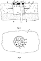
- 1 and 2 is a first embodiment of a bushing device 20 for several lines 7 (only one is shown), which is shown in a round opening in cross section of a horizontal soleplate 8 one building with no basement. 1 closes above the soleplate 8 to the inside I of a building, while below the Base plate 8 a layer of sand 9 is arranged in the building exterior A.
- the Longitudinal axis LA of the mounted bushing device 20 forms with a axis WA extending perpendicularly through the base plate 8 makes an angle of approximately 45 °.
- the feedthrough device 20 comprises - as explained in more detail below Casing tube 1 through which the lines 7 are passed.
- Casing tube 1 through which the lines 7 are passed.
- the casing 1 can be braced in the front area near the inside of the building Sealant 2, 3, 4 for sealing the area between the casing 1 and the Lines 7, and a support element 6 in the opposite end region arranged to support the line 7.
- the casing tube 1 which is circular in cross section, is, for example, made of a made of metallic material, plastic or fiber cement and dresses the Inner wall completely and sealing the breakthrough.
- the cut edges of the both ends of the casing 1 run parallel to each Base plate 8 and protrude in the vertical direction a predetermined dimension into the interior of the building I or the sand layer 9 into it.
- the sealing means 2, 3, 4 comprise a first and a second, each circular Flange plate 2, 4 preferably made of steel and one between the two Flange plates 2, 4, cylindrical sealing bodies 3 arranged in sandwiches made of an elastically deformable material.
- first flange plate 2 below and the second flange plate 4 above the sealing body 3 arranged.
- the sealing body 3 (in the unstressed state) and the first flange plate 2 have only a slightly smaller diameter than that Inner diameter of the casing 1.
- the second flange plate 4, the Building I is directed, it has a smaller diameter compared.
- the sealing means 2, 3, 4 are arranged in the casing 1 so that their Longitudinal axes coincide with the longitudinal axis LA of the casing 1 and that the - with respect to FIG. 1 - the highest circumferential section approximately Height of the top of the soleplate 8 is located. Because of the slant in the soleplate arranged casing 1, the two flange plates 2, 4 and the sealing body 3 in the radial direction at an angle of approximately 45 ° with respect to the Vertical inclined.
- the flange plates 2, 4 and the sealing body 3 each have four, together aligned openings, which are at the same radial distance around the Longitudinal axis LA are arranged.
- Those that can be passed through the openings Lines 7 are, for example, pipes and / or cables. Of course, one other number of lines and openings to be carried out provided be.
- the flange plates 2, 4 and the sealing body 3 each have four through holes aligned with one another on, through which studs 5 can be carried out. 1 and 2
- the illustrated embodiment is through each through hole from the first Flange plate 2 ago a stud screw 5 inserted, the sealing body 3 and Push through the second flange plate 4.
- a hexagon nut 5a is screwed onto the projecting end.
- the first flange plate 2 lies circumferentially on the inner wall of the casing 1 and is all around with it on the outside of the building A facing Welded side at welding points 25.
- a bearing ring for example, glued to one of the two flange plates 2, 4 and in the event of the occurrence of axial forces is supported; preferably the first flange plate 2 rests on the bearing ring, which in this case is arranged between the support element 6 and the flange plate 2 is and is attached circumferentially to the casing 1.
- the line 7 is in the embodiment of FIGS. 1 and 2 made of a metallic Workpiece manufactured and through an opening in the two flange plates 2, 4 and in the sealing body 3.
- Line 7 is in her Circumferentially welded to the first flange plate 2 at points 26, which - like the welding points 25 - on the Sealing body 3 are facing away and the axial and radial deformation of the Do not affect the sealing body 3.
- the support element 6 made of preferably metal with the inner wall of the casing 1 welded.
- the plate-shaped support element 6 has an elongated, radial section pointing inside the casing, one end of which is firmly attached to the Casing 1 is connected and at the other end a closed Connects ring section.
- the ring section extends so far into the inner casing that it is arranged approximately at the level of the transition from the base plate 8 to the layer of sand 9.
- the line 7 is passed through the ring section of the support element 6 and welded to the ring portion in the peripheral region.
- the longitudinal axis of the Line 7 runs parallel to the longitudinal axis of the casing 1.
- the line 7 goes to the through the bushing then guided line section - in an arc with a large Radius in a usually parallel and at a short distance to the base plate 8 in of the sand layer 9 extending outer line section over (not shown).
- the forces applied to the line are absorbed by the support element 6.
- Fig. 1 it can also be seen that on the outside of the casing 1 Metallic anchoring means 1a extending parallel to the base plate 8 are welded on.
- the anchoring means 1a are around the casing 1 circumferential circular disk-shaped outer flange 1a formed in the middle in the Sole plate 8 is anchored.
- the implementation device 20 is in this Embodiment placed before pouring the concrete base plate 8, so that the concrete, the outer flange 1a and the casing 1 form-fitting includes and stabilizes.
- the outer flange 1a also takes over the function an additional lock for ascending on the outer wall of the casing 1 Humidity.
- the opening can be coated be lined, for example with a special varnish.
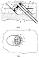
- the second exemplary embodiment shown in FIGS. 3 and 4 differs from the first embodiment essentially in the orientation of the bushing 20 in the horizontal soleplate 8. Instead of an oblique one Arrangement runs through device 20 of the second embodiment vertically through the bottom plate 8. This means that the line 7 is guided vertically through the wall bushing.
- the sealants 2, 3, 4 are located here - in relation to FIG. 3 - the upper end area of the bushing device 20, while the support element 6 in its lower end face Area is arranged.
- FIGS. 5-8 which are oblique (Fig. 5, 6) and a vertical (Fig. 7, 8) extending through a sole plate 8
- Implement device 20 show differ from those previously described Embodiments essentially through the additional Use of at least one empty pipe 11 (only one is shown) in which is guided at least one line 7.
- the circular in cross section Empty pipes 11 made of metal or plastic have a smaller diameter than the casing 1 so that several empty pipes 11 in side by side without problems Longitudinal direction in the bushing device 20 and through various openings can be guided in the sealing means 2, 3, 4.
- the empty tube 11 is provided by a support element 6 out, which is in approximately the same position as the support element 6 of the Embodiment of FIG. 1 is arranged and the empty tube 11 for support the line 7 stops.
- a sealing ring 10 is arranged, which is essentially at a leakage of a gas-carrying line 7 outside the building of the gas between conduit 11 and line 7 prevented.
- An armature disk 13 made of metal is pushed onto the metallic line 7 Inner diameter is slightly larger than the outer diameter of the line 7.
- the armature disk 13 is circumferential with the line in the region of its inner circumference 7 welded at points 29 and centered on the second flange plate 4 Opening for the empty pipe 11 or the line 7 placed and by means of Fastening screws 12 screwed in from inside I of the building.
- A can be between the armature plate 13 and the second flange plate 4
- Sealing element 14 may be arranged in the event of the empty tube being torn out 11 penetration of gas between the armature disk 13 and the sealing body 3 second flange plate 4 prevented.
- the Breakthrough line 7 from a relatively short piece of gas pipe 7 is formed, which has connection options for outside at both ends and has cables laid inside the building.
- a Force limiter in a from the outside to the bushing device 20 steel gas pipe installed, which prevents excessive tensile load -
- the gas line is detected by an excavator - the gas line in the The interior of the building is torn off. It becomes a transition piece to that of the building steel gas pipe piece opening on the outside, which is connected to a Plastic pipe laid outside is connected.
- the plastic line breaks in this arrangement rather than the metallic gas line, so that no gas into Can penetrate inside the building.
- the curved or oblique course of the bushing 20 through the Sole plate 8 also reduces the risk of tearing off with relatively large tensile forces. Act from the outside on what is usually laid parallel to the base plate 8 Supply pipe such tensile forces, these forces act with an axial and a radial component. While the axial component due to the above described structural features to no damage to the gas line inside the building, the radial component causes an angular movement, which, however, does not damage the gas line due to the support element 6, can break at the sealing elements 2, 3, 4 or within the building.
- FIGS. 5 to 8 To assemble the sealing devices shown in FIGS. 5 to 8 first cast the casing 1 in the base plate 8 together with the Empty pipe 11. Then the sealing body 3, the flange plate 4 and Hexagon nuts 5a mounted on the stud bolts 5. The gas pipe section 7, which is welded to the armature disk 13 in the area of the weld seam 29, is inserted into the empty tube 11 until the armature disk 13 for contact with the Flange plate 4 comes. Then the armature plate 13 by means of fastening screws 12 releasably connected to the flange plate 4, being between the Armature disk 13 and the flange plate 4, a sealing element 14 is arranged. In the assembled state, the gas pipe section 7 projects through the support element 6.
- the gas pipe section 7 is in the outer region A in a manner not shown by means of a Transition piece connected to a plastic line, so that in the area of Transition piece is a predetermined breaking point, which is exceeded when a certain (tensile) force on the power tube section 7 for a defined breaking of the Gas pipe in outside area A ensures.
- a certain (tensile) force on the power tube section 7 for a defined breaking of the Gas pipe in outside area A ensures.
- possibly from the Gas flowing out of the gas line is attached to it by the sealing device 20 prevented from flowing to the inside of the building I.
- This is ensured by the sealing ring 10 between empty pipe 11 and gas pipe section 7, the sealing ring 10 in the area of Sealing body 3, the sealing element 14 and the one formed by the weld 29 Welded joint.
- the sealing rings 10 are for preventing the inflow of gas in the interior of the building is not absolutely necessary.
- the empty tubes 11 preferably have a length such that they only protrude straight out of the building.
- the protruding ends can be done with the help of coupling sleeves are connected to so-called energy channels regularly include several empty pipes for supply lines. The connection is such that no axial forces on the protruding from the building Empty pipes are transferred.
- the feedthrough device 20 allows multiple supply lines of various kinds to pass through them.
- a Support element 6 may be provided for the gas pipe section 7, while the other supply lines may not need corresponding support elements 6, since they may be made of more flexible materials and a Tearing off is less likely under tensile loads.
- the support element can also be designed so that all lines to be carried out on the previously supports the manner described.
- the feedthrough device 20 is not only - as shown in the exemplary embodiments - in horizontal Walls or sole plates 8 can be used, but in walls of any orientation and shape.
- the support member 6 and the empty tubes 11 plastics usable by Gluing or welding can be connected to each other.
Landscapes
- Engineering & Computer Science (AREA)
- Architecture (AREA)
- Civil Engineering (AREA)
- Structural Engineering (AREA)
- General Engineering & Computer Science (AREA)
- Mechanical Engineering (AREA)
- Supports For Pipes And Cables (AREA)
- Gasket Seals (AREA)
Applications Claiming Priority (2)
| Application Number | Priority Date | Filing Date | Title |
|---|---|---|---|
| DE1997140458 DE19740458A1 (de) | 1997-09-15 | 1997-09-15 | Durchführungsvorrichtung |
| DE19740458 | 1997-09-15 |
Publications (1)
| Publication Number | Publication Date |
|---|---|
| EP0902225A1 true EP0902225A1 (fr) | 1999-03-17 |
Family
ID=7842355
Family Applications (1)
| Application Number | Title | Priority Date | Filing Date |
|---|---|---|---|
| EP98117429A Withdrawn EP0902225A1 (fr) | 1997-09-15 | 1998-09-15 | Dispositif de traversée |
Country Status (2)
| Country | Link |
|---|---|
| EP (1) | EP0902225A1 (fr) |
| DE (1) | DE19740458A1 (fr) |
Cited By (1)
| Publication number | Priority date | Publication date | Assignee | Title |
|---|---|---|---|---|
| EP3288130A1 (fr) * | 2016-08-24 | 2018-02-28 | Hauff-Technik GmbH & Co. KG | Utilisation d'une traversée de mur destinée à être installée dans un mur extérieur de bâtiment |
Citations (4)
| Publication number | Priority date | Publication date | Assignee | Title |
|---|---|---|---|---|
| US2459370A (en) * | 1946-05-15 | 1949-01-18 | Presstite Engineering Company | Packing assembly |
| DE1204472B (de) * | 1962-10-09 | 1965-11-04 | Rheinisches Metallwerk Gmbh | Mauerdurchfuehrung fuer Installationsrohre mit einem radial verspannbaren Pressring |
| EP0681135A2 (fr) * | 1994-05-07 | 1995-11-08 | Werner Hauff | Dispositif pour le passage d'un conduit à travers une ouverture dans un mur |
| DE29708971U1 (de) * | 1997-03-10 | 1997-07-03 | DOYMA GmbH & Co., 28876 Oyten | Wanddurchführung mit topfförmiger Dichtungseinheit |
Family Cites Families (4)
| Publication number | Priority date | Publication date | Assignee | Title |
|---|---|---|---|---|
| DE7608291U1 (de) * | 1976-03-18 | 1976-09-30 | Kabel- Und Metallwerke Gutehoffnungshuette Ag, 3000 Hannover | Buchse mit haltevorrichtung fuer die wasserdichte durchfuehrung eines leitungsrohres, kabels etc. durch eine wand |
| DE9205564U1 (de) * | 1992-04-24 | 1992-08-27 | Doyma-Rohrdurchführungstechnik Hans-Ullrich Ihlenfeldt, 2806 Oyten | Durchführung für Rohre o.ä. |
| DE9318092U1 (de) * | 1993-11-26 | 1994-03-17 | DOYMA-Rohrdurchführungstechnik Hans-Ullrich Ihlenfeldt, 28876 Oyten | Dichtungseinsatz für in einem Futterrohr geführte Rohrleitungen |
| DE29517409U1 (de) * | 1995-11-03 | 1997-03-13 | DOYMA GmbH & Co., 28876 Oyten | Kabeldurchführung mit Schutzrohr |
-
1997
- 1997-09-15 DE DE1997140458 patent/DE19740458A1/de not_active Withdrawn
-
1998
- 1998-09-15 EP EP98117429A patent/EP0902225A1/fr not_active Withdrawn
Patent Citations (4)
| Publication number | Priority date | Publication date | Assignee | Title |
|---|---|---|---|---|
| US2459370A (en) * | 1946-05-15 | 1949-01-18 | Presstite Engineering Company | Packing assembly |
| DE1204472B (de) * | 1962-10-09 | 1965-11-04 | Rheinisches Metallwerk Gmbh | Mauerdurchfuehrung fuer Installationsrohre mit einem radial verspannbaren Pressring |
| EP0681135A2 (fr) * | 1994-05-07 | 1995-11-08 | Werner Hauff | Dispositif pour le passage d'un conduit à travers une ouverture dans un mur |
| DE29708971U1 (de) * | 1997-03-10 | 1997-07-03 | DOYMA GmbH & Co., 28876 Oyten | Wanddurchführung mit topfförmiger Dichtungseinheit |
Cited By (2)
| Publication number | Priority date | Publication date | Assignee | Title |
|---|---|---|---|---|
| EP3288130A1 (fr) * | 2016-08-24 | 2018-02-28 | Hauff-Technik GmbH & Co. KG | Utilisation d'une traversée de mur destinée à être installée dans un mur extérieur de bâtiment |
| EP3582351A1 (fr) * | 2016-08-24 | 2019-12-18 | Hauff-Technik GmbH & Co. KG | Utilisation d'une entrée de mur de bâtiment destinée à être installée dans un mur de bâtiment |
Also Published As
| Publication number | Publication date |
|---|---|
| DE19740458A1 (de) | 1999-03-18 |
Similar Documents
| Publication | Publication Date | Title |
|---|---|---|
| DE69613924T2 (de) | Variabel einzubettender Anker und Verfahren | |
| DE29906645U1 (de) | Durchführungs-Vorrichtung zum abgedichteten Durchführen mindestens einer Leistung durch einen in der Wand o.dgl. ausgebildeten Durchbruch | |
| EP0246219B1 (fr) | Passage pour tuyau | |
| EP0902225A1 (fr) | Dispositif de traversée | |
| DE102005005861A1 (de) | Verbindungs- und Modulsystem zur Erstellung von druckwasserfesten Bauwerken aus Betonfertigteilen | |
| EP0566973B1 (fr) | Traversée pour tuyaux ou similaires | |
| DE102014111691B4 (de) | Dichtungsanordnung an einer Bauwerkswand | |
| DE3302075A1 (de) | Spannbeton- oder stahlbetonbiegetraeger | |
| EP0286023B1 (fr) | Dispositif pour la protection de canalisations de gaz | |
| DE102004054947B4 (de) | Zugfeste Anordnung von zwei ineinander angeordneten Rohren zum Einführen wenigstens eines Kabels oder Rohres in ein Gebäude | |
| WO2014072013A1 (fr) | Dispositif pour la fermeture étanche au gaz d'un récipient, en particulier d'un réacteur à biogaz, ainsi que récipient présentant un tel dispositif | |
| DE4119125C1 (fr) | ||
| EP0898675A1 (fr) | Fourreau mural avec unite d'etancheite en forme de pot | |
| DE102008016330A1 (de) | Schutzrohrsystem | |
| DE3232221A1 (de) | Verbindung eines kunststoffummantelten stahlrohres mit einem kunststoffrohr | |
| DE102015224118A1 (de) | Spannschloss mit Adapter zum Verbinden von Betonfertigteilen | |
| DE102022124383A1 (de) | Ins Erdreich einzubauender Schacht mit einem Sicherungsanker sowie Sicherungsanker dafür | |
| EP1446541B1 (fr) | Jointure faciale entre deux elements de tole de toiture pour un toit plat et element de tole de toiture concu a cette fin | |
| DE29708971U1 (de) | Wanddurchführung mit topfförmiger Dichtungseinheit | |
| DE60309311T2 (de) | Rohrabzweigung mit buchse mit einer keilförmigen nut und keil zum einführen in die buchse | |
| DE4243460C1 (de) | Gasrohrsanierungsanordnung | |
| EP0877187B1 (fr) | Traversée murale pour des tuyaux ou des câbles | |
| DE29815046U1 (de) | Gebäudeanschlußvorrichtung für Versorgungsleitungen | |
| DE102014111693A1 (de) | Dichtungsanordnung mit geteiltem Kunststoffflansch | |
| DE3137792A1 (de) | Hausanschluss-gasleitung |
Legal Events
| Date | Code | Title | Description |
|---|---|---|---|
| PUAI | Public reference made under article 153(3) epc to a published international application that has entered the european phase |
Free format text: ORIGINAL CODE: 0009012 |
|
| AK | Designated contracting states |
Kind code of ref document: A1 Designated state(s): AT BE CH CY DE DK ES FI FR GB GR IE IT LI LU MC NL PT SE |
|
| AX | Request for extension of the european patent |
Free format text: AL;LT;LV;MK;RO;SI |
|
| AKX | Designation fees paid | ||
| STAA | Information on the status of an ep patent application or granted ep patent |
Free format text: STATUS: THE APPLICATION IS DEEMED TO BE WITHDRAWN |
|
| 18D | Application deemed to be withdrawn |
Effective date: 19990918 |
|
| REG | Reference to a national code |
Ref country code: DE Ref legal event code: 8566 |