EP0901808A2 - Verfahren und Anlage zur Behandlung der Abluft aus thermischen Trocknungsprozessen - Google Patents
Verfahren und Anlage zur Behandlung der Abluft aus thermischen Trocknungsprozessen Download PDFInfo
- Publication number
- EP0901808A2 EP0901808A2 EP98116345A EP98116345A EP0901808A2 EP 0901808 A2 EP0901808 A2 EP 0901808A2 EP 98116345 A EP98116345 A EP 98116345A EP 98116345 A EP98116345 A EP 98116345A EP 0901808 A2 EP0901808 A2 EP 0901808A2
- Authority
- EP
- European Patent Office
- Prior art keywords
- process gas
- sewage sludge
- drying
- moisture
- gas stream
- Prior art date
- Legal status (The legal status is an assumption and is not a legal conclusion. Google has not performed a legal analysis and makes no representation as to the accuracy of the status listed.)
- Withdrawn
Links
Images
Classifications
-
- F—MECHANICAL ENGINEERING; LIGHTING; HEATING; WEAPONS; BLASTING
- F26—DRYING
- F26B—DRYING SOLID MATERIALS OR OBJECTS BY REMOVING LIQUID THEREFROM
- F26B17/00—Machines or apparatus for drying materials in loose, plastic, or fluidised form, e.g. granules, staple fibres, with progressive movement
- F26B17/02—Machines or apparatus for drying materials in loose, plastic, or fluidised form, e.g. granules, staple fibres, with progressive movement with movement performed by belts carrying the materials; with movement performed by belts or elements attached to endless belts or chains propelling the materials over stationary surfaces
- F26B17/04—Machines or apparatus for drying materials in loose, plastic, or fluidised form, e.g. granules, staple fibres, with progressive movement with movement performed by belts carrying the materials; with movement performed by belts or elements attached to endless belts or chains propelling the materials over stationary surfaces the belts being all horizontal or slightly inclined
-
- B—PERFORMING OPERATIONS; TRANSPORTING
- B01—PHYSICAL OR CHEMICAL PROCESSES OR APPARATUS IN GENERAL
- B01D—SEPARATION
- B01D47/00—Separating dispersed particles from gases, air or vapours by liquid as separating agent
- B01D47/02—Separating dispersed particles from gases, air or vapours by liquid as separating agent by passing the gas or air or vapour over or through a liquid bath
- B01D47/021—Separating dispersed particles from gases, air or vapours by liquid as separating agent by passing the gas or air or vapour over or through a liquid bath by bubbling the gas through a liquid bath
-
- B—PERFORMING OPERATIONS; TRANSPORTING
- B01—PHYSICAL OR CHEMICAL PROCESSES OR APPARATUS IN GENERAL
- B01D—SEPARATION
- B01D53/00—Separation of gases or vapours; Recovering vapours of volatile solvents from gases; Chemical or biological purification of waste gases, e.g. engine exhaust gases, smoke, fumes, flue gases, aerosols
- B01D53/34—Chemical or biological purification of waste gases
- B01D53/74—General processes for purification of waste gases; Apparatus or devices specially adapted therefor
- B01D53/77—Liquid phase processes
- B01D53/78—Liquid phase processes with gas-liquid contact
-
- F—MECHANICAL ENGINEERING; LIGHTING; HEATING; WEAPONS; BLASTING
- F26—DRYING
- F26B—DRYING SOLID MATERIALS OR OBJECTS BY REMOVING LIQUID THEREFROM
- F26B25/00—Details of general application not covered by group F26B21/00 or F26B23/00
- F26B25/005—Treatment of dryer exhaust gases
Definitions
- the invention relates to a method for treating the exhaust air from thermal Drying processes, in particular from processes when drying sewage sludge in Sewage sludge dryers, after which a temperature-controlled process gas flow to the sewage sludge Extracts moisture to a residual moisture.
- EP 0 593 887 B1 discloses a process for the thermal drying of pasty material, in particular sewage sludge, preferably in pelletized form, the moisture of which is absorbed by a dry process gas stream below the mobilization temperature of sludge contents or additives up to a residual moisture .
- the moisture is extracted from the process gas by means of a gas dehumidifier, and within a second process circuit, the moisture bound in the gas dehumidifier is removed by heated regeneration gas.
- the tempered and moisture-laden regeneration gas is either released via a deodoriser or directly into the atmosphere.
- the dehumidification of the process gas and the gas dehumidifier as well as the cleaning of the regeneration gas is associated with relatively high technical and control engineering expenses.
- the method of such a system requires a considerable amount of operating and maintenance effort and relatively high operating costs by the operator.
- a method for thermal treatment in particular for drying a flowable, water-containing material, in particular a sewage sludge, is known, according to which the previously compacted or granulated material is guided in the fluidized bed of a closed fluidized bed apparatus, in which the material by means of built-in heating surfaces is heated to produce an inert gas, which is essentially water vapor, and the fluidized bed is fluidized exclusively with the gas.
- the exhaust gases exceeding the need for gassing the material are discharged from the contact fluid bed dryer via a line branch.
- a cyclone or a filter are connected in this line branch to hygienize the exhaust gases and, for example, a condenser is integrated for heat recovery.
- a relatively high level of equipment and control technology is required, which at the same time requires a certain amount of operation and maintenance.
- a method for drying sewage sludge is also known from DE 40 16 100 A1, according to which the sewage sludge is flowed through from below in a column-like container with tempered drying air. After flowing through the sewage sludge, the heated and moisture-laden air is discharged from the top of the container via an exhaust air line, in which a vacuum is generated in it by means of a blower. A filter is installed downstream of the blower, which is used to keep odors and fermentation gases contained in the exhaust air out of the environment.
- This technically quite simple sewage sludge dryer also requires equipment and control technology as well as operating and maintenance effort to treat the dryer exhaust air in the sense of generating environmentally compatible exhaust air.
- a method for drying sewage sludge for example, is known from DE 40 13 761 A1, according to which the sewage sludge is applied to an air-permeable conveying device as a layered, air-permeable pile and is moved by means of the conveying device through a drying device.
- a temperature-controlled drying gas stream is alternately passed back and forth through the conveying device and through the pile to remove water from the pile.
- the drying gas stream loaded with water is sucked out of the drying device and fed to a condenser in which the drying gas stream is condensed.
- the resulting condensate which is water, can be sent to a sewage treatment plant.
- the method does not disclose how it is avoided that the odorous substances and fermentation gases contained in the drying gas stream do not lead to pollution of the environment.
- the person skilled in the art can assume that, at least in the area of the condensation of the drying gas stream, precautions are taken to neutralize it. These precautions are presented as equipment and control engineering expenses, in addition to the operating and maintenance expenses.
- DE 39 23 020 A1 discloses a process for disposing of adhesive sludges, in particular paint sludges, which contain inorganic pollutants which are environmentally incompatible and evaporate under the influence of heat.
- the tempered drying air loaded with the volatile pollutants is led into an afterburning device in which the pollutants are burned.
- the elimination of the volatile inorganic pollutants that are absorbed by the drying air when drying paint sludge requires the afterburning of the drying air. Afterburning is costly.
- An essential feature of the invention according to claim 1 is that the tempered exhaust air laden with moisture is led into the unpurified water of a wastewater treatment plant.
- the exhaust air which has a temperature of ⁇ 85 ° C, is directed into a channel or into a basin with sufficient waste water volume, in which the exhaust air is cooled to the temperature of the waste water temperature, which is ⁇ 30 ° C, and the water-soluble, odor-intensive substances such as Ammonia or ammonium can be washed out of the exhaust air.
- the exhaust air can be introduced into the waste water in various ways.
- a preferred way can be that the exhaust air is introduced into the waste water via an aeration device associated with the waste water purification system. This is possible because the exhaust air has a normal oxygen content of 21%, which also contains the air that the aeration device uses to aerate the wastewater. Adequate waste water volume is considered if the waste air is introduced, for example, at a depth of ⁇ 1000 mm below the waste water level in the waste water basin, which means that energy-intensive fans can be dispensed with on the plant side.
- the invention advantageously dispenses with the technical and control precautions required for the condensation of the exhaust air moisture and for the purification of the exhaust air. This reduces operating and maintenance costs and operating costs for the operator of the system.
- the process of biological clarification is stimulated to a higher activity by introducing the temperature-controlled and moisture-laden exhaust air into the wastewater of a sewage treatment plant.
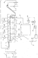
- the process diagram shown in the drawing shows a sewage sludge drying system in combination with the wastewater basin of a wastewater treatment plant.
- the sewage sludge 2 which has a dry substance of about 20% by weight, is fed into a silo 1.
- the sewage sludge 2 is fed via a pipeline 3 to a feed device 4, which is also a pelletizing device.
- the pelletizing device engages sealingly in the first dryer zone 6 of a through-flow dryer consisting of several dryer zones 6 to 9.
- the sewage sludge 2 to be dried is fed into a sieve belt 10, which circulates endlessly within the dryer 5, in pellet form and is transported from the dryer zone 6 to the dryer zones 7 to 9 in a continuous process to a discharge device 11.
- the dried sewage sludge 2 leaves the dryer 5 with a dry substance of approximately 95% by weight.
- a silo 12 receives the dried sewage sludge via the discharge device 11.
- a conveying line 13 can be provided in order to connect the silo 12 to the feed or pelletizing device 4.
- the flow-through dryer 5 is designed in such a way that a process gas stream 14 is sucked in as fresh air from the atmosphere via the pipeline 20, the filter 21 and an actuator 22 by a fan 23 and is supplied to the drying zone 9 when heated by a heating device 24.
- the process gas stream 14 preferably flows in opposite directions, depending on the pressure conditions building up in the dryer 5 and the transport direction 15 of the sewage sludge 2 to be dried, and alternately from top to bottom through the individual dryer zones 9 to 6 and the sieve belt 10.
- the process gas stream leaves the dryer 5 in the zone 6 as a process gas enriched with high humidity at a temperature of approximately 60 to 85 ° C.
- a fan 16 is assigned to each dryer zone 6 to 9 for the necessarily forced process gas transport.
- the process gas leaves the dryer 5 via the pipeline 17.
- the temperature-controlled and moisture-laden exhaust air is passed via line 17 into a basin 18 of a wastewater treatment plant filled with wastewater.
- a fan 19 can also be integrated into the line 17, which supports the transport of the exhaust air in the direction of the waste water basin 18. It is advantageous if the exhaust air is introduced into the wastewater basin 18 of the sewage plant at a relatively shallow depth below the surface 18b of the wastewater 18a.
- the invention can be used for any kind of sewage sludge drying systems are used, in which the exhaust air with organic substances.
Landscapes
- Engineering & Computer Science (AREA)
- Chemical & Material Sciences (AREA)
- Environmental & Geological Engineering (AREA)
- Chemical Kinetics & Catalysis (AREA)
- Analytical Chemistry (AREA)
- Biomedical Technology (AREA)
- Health & Medical Sciences (AREA)
- General Chemical & Material Sciences (AREA)
- Oil, Petroleum & Natural Gas (AREA)
- Mechanical Engineering (AREA)
- General Engineering & Computer Science (AREA)
- Drying Of Solid Materials (AREA)
- Treatment Of Sludge (AREA)
- Treating Waste Gases (AREA)
Abstract
Description
Innerhalb eines ersten Prozesskreislaufs wird dem Prozessgas die Feuchtigkeit mittels eines Gasentfeuchters entzogen und innerhalb eines zweiten Prozesskreislaufs wird die in dem Gasentfeuchter gebundene Feuchtigkeit selbigen durch erhitztes Regenerationsgas entzogen.
Das temperierte und feuchtebelastete Regenerationsgas wird entweder über eine Desodoriereinrichtung oder direkt an die Atmosphäre abgegeben.
Das Entfeuchten des Prozessgases und des Gasentfeuchters sowie das Reinigen des Regenerationsgases ist mit relativ hohen anlagentechnischen und regelungstechnischen Aufwendungen verbunden. Gleichzeitig erfordert das Verfahren einer solchen Anlage durch den Betreiber einen erheblichen Bedien- und Wartungsaufwand und relativ hohe Betriebskosten.
Die den Bedarf der Begasung des Materials übersteigenden Abgase werden aus dem Kontaktfließbetttrockner über einen Leitungszweig abgeführt. In diesem Leitungszweig sind zur Hygenisierung der Abgase ein Zyklon bzw. ein Filter geschaltet und zur Wärmerückgewinnung z.B. ein Kondensator eingebunden.
Zur Hygenisierung und Filterung des Abgases ist ein relativ hoher geräte- und regelungstechmischer Aufwand erforderlich, der zugleich einen gewissen Bedien- und Wartungsaufwand erforderlich macht.
Nach dem Durchströmen des Klärschlamms wird die erwärmte und mit Feuchtigkeit beladene Luft von der Oberseite des Behälters über eine Abluftleitung abgeführt, indem in dieser mittels eines Gebläses ein Unterdruck erzeugt wird. Dem Gebläse ist ein Filter nachgeschaltet, der dazu dient, in der Abluft enthaltene Geruchsstoffe und Faulgase von der Umgebung abzuhalten.
Auch dieser technisch recht einfach ausgeführte Klärschlamm-Trockner erfordert zur Behandlung der Trocknerabluft im Sinne der Erzeugung einer umweltverträglichen Abluft geräte- und regelungstechnischen Aufwand sowie Bedien- und Wartungsaufwand.
Der mit Wasser beladene Trocknungsgasstrom wird aus der Trockeneinrichtung gesaugt und einem Kondensator zugeführt, in dem der Trocknungsgasstrom kondensiert wird. Das anfallende Kondensat, bei dem es sich um Wasser handelt, kann einem Klärwerk zugeführt werden.
Das Verfahren offenbart nicht, wie vermieden wird, dass die in dem Trocknungsgasstrom enthaltenen Geruchsstoffe und Faulgase nicht zu einer Belastung der Umwelt führen. Der Fachmann kann davon ausgehen, dass zumindest im Bereich der Kondensierung des Trocknungsgasstromes Vorkehrungen zu dessen Neutralisierung getroffen sind. Diese Vorkehrungen stellen sich als geräte- und regelungstechnischer Aufwand dar, zu dem noch der Bedien- und Wartungsaufwand hinzukommt.
Die Beseitigung der flüchtigen anorganischen Schadstoffe, die beim Trocknen von Lackschlämmen von der Trocknungsluft aufgenommen werden, erfordert das Nachverbrennen der Trocknungsluft. Das Nachverbrennen ist kostenaufwendig.
Wesentliches Merkmal der Erfindung nach dem Anspruch 1 ist, dass die mit Feuchte beladene temperierte Abluft in das ungereinigte Wasser einer Abwasserteinigungsanlage geführt wird. Dabei wird die eine Temperatur von < 85 °C aufweisende Abluft in eine Rinne oder in ein Becken mit hinreichendem Abwasservolumen geleitet, in dem die Abluft auf die Temperatur der Abwassertemperatur, die < 30 °C beträgt, gekühlt und die wasserlöslichen, geruchsintensiven Stoffe, wie Ammoniak oder Ammonium aus der Abluft ausgewaschen werden.
Das Einbringen der Abluft in das Abwasser kann dabei auf verschiedenen Wegen erfolgen. Ein bevorzugter Weg kann sein, dass die Abluft über eine der Abwasserreinigungsanlage beigeordnete Belüftungseinrichtung in das Abwasser eingebracht wird. Dies ist deshalb möglich, weil die Abluft einen normalen Sauerstoffanteil von 21 % besitzt, den auch die Luft besitzt, die die Belüftungseinrichtung zur Belüftung des Abwassers verwendet. Als hinreichendes Abwasservolumen wird angesehen, wenn die Abluft in z.B. in einer Tiefe von < 1000 mm unterhalb des Abwasserspiegels im Abwasserbecken eingebracht wird, wodurch anlagenseitig auf energieintensive Lüfter verzichtet werden kann.
Für den Betreiber der Anlage vermindern sich dadurch der Bedien- und Wartungsaufwand und die Betriebskosten. Durch das Einleiten der temperierten und feuchtebelasteten Abluft in das Abwasser einer Kläranlage wird der Prozess der biologischen Klärung zu einer höheren Aktivität angeregt.
Ein Silo 12 nimmt den getrockneten Klärschlamm über die Austragvorrichtung 11 auf.
Eine Förderleitung 13 kann vorgesehen sein, um das Silo 12 mit der Zuführ- oder Pelletiervorrichtung 4 zu verbinden.
Der Prozessgasstrom 14 durchströmt dabei vorzugsweise, in Abhängigkeit von den sich im Trockner 5 aufbauenden Druckverhältnissen und der Transportrichtung 15 des zu trocknenden Klärschlamms 2 entgegengesetzt und abwechselnd von oben nach unten die einzelnen Trocknerzonen 9 bis 6 und das Siebband 10.
Schließlich verlässt der Prozessgasstrom den Trockner 5 in der Zone 6 als mit hoher Feuchtigkeit angereichertes Prozessgas bei einer Temperatur von etwa 60 bis 85 °C.
Gemäß der Erfindung wird die temperierte und feuchtebeladene Abluft über die Leitung 17 in ein mit Abwasser gefülltes Becken 18 einer Abwasserkläranlage geleitet. In die Leitung 17 kann zusätzlich ein Ventilator 19 eingebunden sein, der den Transport der Abluft in Richtung des Abwasserbeckens 18 unterstützt.
Von Vorteil ist dabei, wenn die Abluft in einer relativ geringen Tiefe unterhalb der Oberfläche 18b des Abwassers 18a in das Abwasserbecken 18 der Kläranlage eingebracht wird.
- 01
- Silo
- 02
- Klärschlamm
- 03
- Rohrleitung
- 04
- Zuführ- und Pelletiervorrichtung
- 05
- Durchström-Trockner
- 06
- Trocknerzone
- 07
- Trocknerzone
- 08
- Trocknerzone
- 09
- Trocknerzone
- 10
- Siebband
- 11
- Austragsvorrichtung
- 12
- Silo
- 13
- Förderleitung
- 14
- Prozessgasstrom
- 15
- Transportrichtung
- 16
- Ventilator
- 17
- Rohrleitung
- 18
- Abwasserbecken
- 18a
- Abwasser
- 18b
- Oberfläche
- 19
- Ventilator
- 20
- Rohrleitung
- 21
- Filter
- 22
- Stellorgan
- 23
- Ventilator
- 24
- Heizeinrichtung
Claims (6)
- Verfahren zur Behandlung der Abluft aus thermischen Trocknungsprozessen, insbesondere aus Trocknungsprozessen, in Klärschlamm-Trocknungsanlagen, wonach ein temperierter Prozessgasstrom dem Klärschlamm die Feuchte bis zu einer verbleibenden Restfeuchte entzieht und aus der Trocknungsanlage ein temperierter, feuchtebelasteter und umweltbelastender Prozessgasstrom geleitet wird, dadurch gekennzeichnet, dass der Prozessgasstrom in das Abwasser einer Abwasserreinigungsanlage geleitet wird.
- Verfahren zur Behandlung der Abluft aus thermischen Trocknungsprozessen, insbesondere aus Trocknungsprozessen, in Klärschlamm-Trocknungsanlagen, wonach ein temperierter Prozessgasstrom dem Klärschlamm die Feuchte bis zu einer verbleibenden Restfeuchte entzieht und aus der Trocknungsanlage ein temperierter, feuchtebelasteter und umweltbelastender Prozessgasstrom geleitet wird, dadurch gekennzeichnet, dass der Prozessgasstrom über die Belüftungseinrichtung einer Abwasserreinigungsanlage in das Abwasser geleitet wird.
- Verfahren nach Anspruch 1, dadurch gekennzeichnet, dass das Prozessgas in ein vor der Klärstufe vorhandenes Abwasser der Abwasserreinigungsanlage eingeleitet wird.
- Verfahren nach Anspruch 1, dadurch gekennzeichnet, dass das Prozessgas in ein mit Abwasser gefülltes Klärbecken geleitet wird.
- Verfahren nach Anspruch 1 bis 4, dadurch gekennzeichnet, dass das Prozessgas in einem Abstand von vorzugsweise weniger als 1000 mm unterhalb der Oberfläche des Abwassers in das Klärbecken geleitet wird.
- Anlage zur Verfahrensdurchführung nach Patentanspruch 1 oder 2, bestehend aus wenigstens einem Klärschlamm-Trockner (5), der während des Trocknungsprozesses einen temperierten, feuchtebeladenen und umweltbelastenden Prozessgasstrom (14) abgibt, und aus wenigstens einem mit dem wenigstens einen Klärschlamm-Trockner (5) zusammenwirkenden Abwasserbecken (18) zum Klären von im Wesentlichen organische Bestandteile enthaltenden Abwässern (18a) einer Abwasser-Kläranlage.
Applications Claiming Priority (2)
| Application Number | Priority Date | Filing Date | Title |
|---|---|---|---|
| DE19739864 | 1997-09-11 | ||
| DE19739864A DE19739864A1 (de) | 1997-09-11 | 1997-09-11 | Verfahren zur Behandlung der Abluft aus thermischen Trocknungsprozessen, insbesondere aus Prozessen beim Trocknen von Klärschlamm in Klärschlamm-Trocknern und Anlage zur Verfahrensdurchführung |
Publications (2)
| Publication Number | Publication Date |
|---|---|
| EP0901808A2 true EP0901808A2 (de) | 1999-03-17 |
| EP0901808A3 EP0901808A3 (de) | 1999-08-04 |
Family
ID=7841960
Family Applications (1)
| Application Number | Title | Priority Date | Filing Date |
|---|---|---|---|
| EP98116345A Withdrawn EP0901808A3 (de) | 1997-09-11 | 1998-08-28 | Verfahren und Anlage zur Behandlung der Abluft aus thermischen Trocknungsprozessen |
Country Status (4)
| Country | Link |
|---|---|
| US (1) | US6101739A (de) |
| EP (1) | EP0901808A3 (de) |
| JP (1) | JPH11137950A (de) |
| DE (1) | DE19739864A1 (de) |
Cited By (6)
| Publication number | Priority date | Publication date | Assignee | Title |
|---|---|---|---|---|
| EP2587203A1 (de) * | 2011-10-26 | 2013-05-01 | Stela Laxhuber GmbH | Bandtrockner |
| CN103768920A (zh) * | 2013-12-31 | 2014-05-07 | 苏州泥宝环境科技有限公司 | 一种污水污泥干化尾气的处理方法及其处理装置 |
| CN105498431A (zh) * | 2016-01-29 | 2016-04-20 | 大连科林能源工程技术开发有限公司 | 一种木质纤维干燥装置尾气环保处理系统 |
| CN105536412A (zh) * | 2016-01-29 | 2016-05-04 | 大连科林能源工程技术开发有限公司 | 一种高效除水雾回收工业用水的节水装置系统 |
| CN106066124A (zh) * | 2016-06-16 | 2016-11-02 | 含山县天翔铸造有限公司 | 一种铸铁件表面防锈处理快速风干装置 |
| CN112275061A (zh) * | 2020-10-16 | 2021-01-29 | 娲石水泥集团有限公司 | 一种水泥包装车间无组织排放治理系统及其方法 |
Families Citing this family (29)
| Publication number | Priority date | Publication date | Assignee | Title |
|---|---|---|---|---|
| FI971899A7 (fi) * | 1997-05-02 | 1998-11-03 | Sunds Defibrator Panelhandling | Menetelmä ja laitteisto levymäisen materiaalin käsittelemiseksi kaasum aisella aineella |
| AU7420298A (en) * | 1997-05-09 | 1998-12-08 | Solutions Mabarex Inc. | Method for reducing moisture content |
| KR100395119B1 (ko) * | 2000-12-29 | 2003-08-21 | 한국에너지기술연구원 | 하.폐수슬러지 건조장치 |
| JP3780883B2 (ja) * | 2001-08-14 | 2006-05-31 | コニカミノルタビジネステクノロジーズ株式会社 | 画像処理装置および画像処理方法 |
| US7651619B2 (en) * | 2001-12-28 | 2010-01-26 | Danmarks Tekniske Universitet (Dtu) | Filtration method and apparatus |
| DE10323774A1 (de) * | 2003-05-26 | 2004-12-16 | Khd Humboldt Wedag Ag | Verfahren und Anlage zur thermischen Trocknung eines nass vermahlenen Zementrohmehls |
| EP1491253A1 (de) * | 2003-06-26 | 2004-12-29 | Urea Casale S.A. | Vorrichtung und Verfahren zur Wirbelschichtgranulation |
| DE102005017187B4 (de) * | 2005-04-13 | 2007-06-21 | Lindauer Dornier Gmbh | Durchlauftrockner in Mehretagenbauweise, insbesondere für plattenförmige Produkte |
| CN101671106B (zh) * | 2009-09-28 | 2012-11-07 | 广州普得环保设备有限公司 | 一种污泥滤饼好氧风干的方法及装置 |
| FR2953005B1 (fr) * | 2009-11-23 | 2011-12-09 | Degremont | Procede et installation de sechage de matieres pateuses, en particulier de boues de stations d'epuration |
| DE102011101059B3 (de) * | 2011-05-09 | 2012-04-26 | Probat-Werke Von Gimborn Maschinenfabrik Gmbh | Vorrichtung zur Wärmebehandlung eines schüttfähigen pflanzlichen Gutes |
| CN102626965B (zh) * | 2012-04-23 | 2014-03-12 | 中国天辰工程有限公司 | 一种abs粉体的干燥方法 |
| CN102976575A (zh) * | 2012-11-29 | 2013-03-20 | 广州市越堡水泥有限公司 | 水泥窑处理污泥系统及方法 |
| US8959793B2 (en) * | 2013-03-14 | 2015-02-24 | International Thermal Systems, Inc. | Pin oven with a continuous U-shaped duct |
| CN104230040B (zh) * | 2013-06-17 | 2016-06-01 | 佛山市高明贝斯特陶瓷有限公司 | 一种陶瓷行业废热气污水循环利用处理系统 |
| CN103435243B (zh) * | 2013-08-12 | 2014-09-03 | 浙江大学 | 利用烟气余热的并联式污泥低温干化系统 |
| CN103411388A (zh) * | 2013-08-26 | 2013-11-27 | 安阳九州药业有限责任公司 | 一种红霉素的干燥方法 |
| EP2933591B1 (de) * | 2014-04-16 | 2017-05-10 | Europool S.r.l. | Trocknungsvorrichtung zum Trocknen von Behältern |
| CN104140187B (zh) * | 2014-07-18 | 2015-12-02 | 天华化工机械及自动化研究设计院有限公司 | 一种污泥蒸汽管回转干燥机干燥方法 |
| DE102015106120A1 (de) * | 2015-04-21 | 2016-10-27 | Huber Se | Verfahren zum Trocknen von Feuchtgut sowie Trocknungsanlage |
| DE102015209370B3 (de) * | 2015-05-21 | 2016-09-08 | Lavatec Laundry Technology Gmbh | Trockner |
| CN105366905B (zh) * | 2015-12-15 | 2019-03-29 | 南安市先创环保技术服务有限公司 | 一种污泥的脱水干燥罐体 |
| CN105366900B (zh) * | 2015-12-15 | 2018-12-18 | 南安市先创环保技术服务有限公司 | 一种脱水性能改良的污泥处理设备 |
| CN105502885A (zh) * | 2016-01-15 | 2016-04-20 | 中和荣华环保科技(北京)有限公司 | 一种两段回流式污泥石灰稳定干化系统 |
| WO2017140648A1 (en) * | 2016-02-15 | 2017-08-24 | Basell Polyolefine Gmbh | Process for the preparation of a dried powder |
| AT518659B1 (de) * | 2016-08-24 | 2017-12-15 | Holcim Technology Ltd | Verfahren und Vorrichtung zur Trocknung von Müll |
| CN107055993B (zh) * | 2017-05-18 | 2023-04-18 | 江苏金圆新材科技有限公司 | 一种含铜污泥造粒和预烘干的装备及工艺方法 |
| CN108862995B (zh) * | 2018-07-09 | 2021-10-12 | 广州市浩逸环保科技有限公司 | 一种污泥烘干恒温装置 |
| CN116040914A (zh) * | 2023-03-03 | 2023-05-02 | 福建龙净环保股份有限公司 | 一种污泥干燥机、污泥干燥系统和污泥干燥方法 |
Family Cites Families (20)
| Publication number | Priority date | Publication date | Assignee | Title |
|---|---|---|---|---|
| DE2117746A1 (de) * | 1971-04-10 | 1972-10-19 | Aeg Kanis Turbinen | Kombinierte Energieerzeugungs und Abwasserreinigungsanlage |
| JPS5129110B2 (de) * | 1971-04-27 | 1976-08-23 | ||
| US4042494A (en) * | 1971-06-08 | 1977-08-16 | Irvine Ranch Water District | Pressure pipe treatment for sewage |
| DE2541070B2 (de) * | 1975-09-15 | 1980-03-06 | Gebrueder Weiss Kg, 6340 Dillenburg | Verfahren zum kontinuierlichen Kompostieren von organischen Abfällen und/oder Klärschlamm und Einrichtung zur Durchführung des Verfahrens |
| US4172781A (en) * | 1977-06-15 | 1979-10-30 | Standard Oil Company (Indiana) | Waste water process for treatment of strong wastes |
| US4226668A (en) * | 1978-12-14 | 1980-10-07 | Sonic Dehydrators, Inc. | Spray drying apparatus utilizing pulse jet engines |
| CH644683A5 (de) * | 1979-05-28 | 1984-08-15 | Escher Wyss Ag | Verfahren zur thermischen behandlung einer materialschicht. |
| JPS5733714A (en) * | 1980-08-07 | 1982-02-23 | Jgc Corp | Treatment of sludge of waste water treating |
| JPS6038099A (ja) * | 1983-08-08 | 1985-02-27 | Ebara Infilco Co Ltd | 有機性廃棄物の処理方法 |
| US4654144A (en) * | 1986-02-03 | 1987-03-31 | National Distillers And Chemical Corporation | Process for the destruction of noxious gases with ozone |
| JPH0687942B2 (ja) * | 1988-05-19 | 1994-11-09 | 株式会社新潟鉄工所 | 臭気成分の生物脱臭方法 |
| DE3923020A1 (de) * | 1989-07-12 | 1991-01-17 | Bayerische Motoren Werke Ag | Verfahren zum entsorgen von klebenden schlaemmen |
| US5215670A (en) * | 1990-02-26 | 1993-06-01 | Bio Gro Systems, Inc. | Process of drying and pelletizing sludge in indirect dryer having recycled sweep air |
| DE4013761C2 (de) * | 1990-04-28 | 1994-11-24 | Sevar Entsorgung | Verfahren zum Trocknen von pastösem und/oder brockigem Material |
| DE4016100A1 (de) * | 1990-05-18 | 1991-11-21 | Licencia Holding Sa | Verfahren und einrichtung zum trocknen von klaerschlamm |
| DK156290D0 (da) * | 1990-06-28 | 1990-06-28 | Blue Tec As | Fremgangsmaade og anlaeg til toerring af slam |
| US5557873A (en) * | 1990-10-23 | 1996-09-24 | Pcl/Smi, A Joint Venture | Method of treating sludge containing fibrous material |
| CA2109436C (en) * | 1991-05-01 | 2002-02-05 | Level Valley Dairy Company | Wastewater treatment system |
| CA2134871C (en) * | 1992-05-08 | 2001-12-18 | Terence R. Johnson | Integrated carbonaceous fuel drying and gasification process and apparatus |
| DE4235422C2 (de) * | 1992-10-21 | 1997-01-23 | Dornier Gmbh Lindauer | Verfahren zum Trocknen von vorzugsweise in pelletierter Form vorliegenden pastösen Material, insbesondere Klärschlamm und Vorrichtung zur Durchführung des Verfahrens |
-
1997
- 1997-09-11 DE DE19739864A patent/DE19739864A1/de not_active Withdrawn
-
1998
- 1998-08-28 EP EP98116345A patent/EP0901808A3/de not_active Withdrawn
- 1998-09-09 US US09/150,357 patent/US6101739A/en not_active Expired - Fee Related
- 1998-09-11 JP JP10258329A patent/JPH11137950A/ja active Pending
Cited By (8)
| Publication number | Priority date | Publication date | Assignee | Title |
|---|---|---|---|---|
| EP2587203A1 (de) * | 2011-10-26 | 2013-05-01 | Stela Laxhuber GmbH | Bandtrockner |
| CN103768920A (zh) * | 2013-12-31 | 2014-05-07 | 苏州泥宝环境科技有限公司 | 一种污水污泥干化尾气的处理方法及其处理装置 |
| CN105498431A (zh) * | 2016-01-29 | 2016-04-20 | 大连科林能源工程技术开发有限公司 | 一种木质纤维干燥装置尾气环保处理系统 |
| CN105536412A (zh) * | 2016-01-29 | 2016-05-04 | 大连科林能源工程技术开发有限公司 | 一种高效除水雾回收工业用水的节水装置系统 |
| CN105498431B (zh) * | 2016-01-29 | 2017-06-27 | 大连科林能源工程技术开发有限公司 | 一种木质纤维干燥装置尾气环保处理系统 |
| CN105536412B (zh) * | 2016-01-29 | 2017-12-01 | 大连科林能源工程技术开发有限公司 | 一种高效除水雾回收工业用水的节水装置系统 |
| CN106066124A (zh) * | 2016-06-16 | 2016-11-02 | 含山县天翔铸造有限公司 | 一种铸铁件表面防锈处理快速风干装置 |
| CN112275061A (zh) * | 2020-10-16 | 2021-01-29 | 娲石水泥集团有限公司 | 一种水泥包装车间无组织排放治理系统及其方法 |
Also Published As
| Publication number | Publication date |
|---|---|
| US6101739A (en) | 2000-08-15 |
| DE19739864A1 (de) | 1999-03-18 |
| EP0901808A3 (de) | 1999-08-04 |
| JPH11137950A (ja) | 1999-05-25 |
Similar Documents
| Publication | Publication Date | Title |
|---|---|---|
| EP0901808A2 (de) | Verfahren und Anlage zur Behandlung der Abluft aus thermischen Trocknungsprozessen | |
| EP0593887B1 (de) | Verfahren zum Trocknen von vorzugsweise in pelletierter Form vorliegenden pastösen Material, insbesondere Klärschlamm und Vorrichtung zur Durchführung des Verfahrens. | |
| EP0243358B1 (de) | Verfahren und vorrichtung zum reinigen lösungsmittelbelasteter abluft | |
| DE4315321C2 (de) | Verfahren und Vorrichtung zur Trocknung von Schlämmen und verschmutzten Flüssigkeiten | |
| EP0210196A1 (de) | Verfahren und vorrichtung zum trocknen und konditionieren von hühnermist oder ähnlichen pastösen stoffen. | |
| CH644683A5 (de) | Verfahren zur thermischen behandlung einer materialschicht. | |
| DE69218177T2 (de) | Methode und einrichtung zur behandlung von abgas | |
| EP1328332B9 (de) | Anlage zur reinigung von abgasen | |
| EP0373577B1 (de) | Verfahren zur Aufbereitung von Klärschlämmen und/oder Industrieschlämmen mit organischen Anteilen mittels des Konversionsverfahrens | |
| WO1991012829A1 (en) | Method and apparatus for improving efficiency of fluid use and odor control in in-vessel composting systems | |
| EP1319632A1 (de) | Verfahren und Vorrichtung zur Trocknung von Schlamm, insbesondere von Abwasserschlamm | |
| EP2944368A1 (de) | Verfahren und vorrichtung zur reinigung eines abgasstromes | |
| EP0781741B1 (de) | Verfahren zur Verarbeitung von Schlamm | |
| DE3905133A1 (de) | Verfahren zur entfernung leichtfluechtiger bestandteile aus boeden | |
| DE69204420T2 (de) | Verfahren zum Entfernen von Schadstoffen aus Substrattrocknungsgas. | |
| DE19961691C5 (de) | Verfahren zur Reinigung von Rauchgas | |
| EP0823859A1 (de) | Verfahren zur reinigung von gasströmen | |
| EP0857930A1 (de) | Vorrichtung und Verfahren zum Trocknen von feuchten Feststoffpartikeln in Wirbelschichten | |
| EP3021955B1 (de) | Verfahren und vorrichtung zur reinigung von abluft | |
| AT403549B (de) | Verfahren zur reinigung von abluft und abluftreinigungsanlage | |
| DE19750908C2 (de) | Verfahren und Vorrichtung zur Kompostierung von Abfällen | |
| EP1556656B1 (de) | Verfahren zur konvektiven trocknung von nass- oder feuchtgut | |
| AT409723B (de) | Anlage zur reinigung von schadstoffbelasteten abgasen | |
| EP2124007A1 (de) | Verfahren zum Trocknen von Klärschlamm | |
| DE4412596A1 (de) | Biologisches Container-Bodensanierungsverfahren und Anlage zu dessen Durchführung |
Legal Events
| Date | Code | Title | Description |
|---|---|---|---|
| PUAI | Public reference made under article 153(3) epc to a published international application that has entered the european phase |
Free format text: ORIGINAL CODE: 0009012 |
|
| AK | Designated contracting states |
Kind code of ref document: A2 Designated state(s): AT BE CH DE DK ES FR GB IT LI LU NL PT SE |
|
| AX | Request for extension of the european patent |
Free format text: AL;LT;LV;MK;RO;SI |
|
| PUAL | Search report despatched |
Free format text: ORIGINAL CODE: 0009013 |
|
| AK | Designated contracting states |
Kind code of ref document: A3 Designated state(s): AT BE CH CY DE DK ES FI FR GB GR IE IT LI LU MC NL PT SE |
|
| AX | Request for extension of the european patent |
Free format text: AL;LT;LV;MK;RO;SI |
|
| RIC1 | Information provided on ipc code assigned before grant |
Free format text: 6B 01D 53/34 A, 6F 26B 21/06 B, 6F 26B 17/02 B, 6C 02F 11/12 B |
|
| 17P | Request for examination filed |
Effective date: 19991130 |
|
| AKX | Designation fees paid |
Free format text: AT BE CH DE DK ES FR GB IT LI LU NL PT SE |
|
| 17Q | First examination report despatched |
Effective date: 20010119 |
|
| STAA | Information on the status of an ep patent application or granted ep patent |
Free format text: STATUS: THE APPLICATION HAS BEEN WITHDRAWN |
|
| 18W | Application withdrawn |
Effective date: 20030110 |