EP0901648B1 - Dekorative brillen - Google Patents
Dekorative brillen Download PDFInfo
- Publication number
- EP0901648B1 EP0901648B1 EP97915075A EP97915075A EP0901648B1 EP 0901648 B1 EP0901648 B1 EP 0901648B1 EP 97915075 A EP97915075 A EP 97915075A EP 97915075 A EP97915075 A EP 97915075A EP 0901648 B1 EP0901648 B1 EP 0901648B1
- Authority
- EP
- European Patent Office
- Prior art keywords
- indicia
- temple
- temple piece
- frame
- eyeglasses
- Prior art date
- Legal status (The legal status is an assumption and is not a legal conclusion. Google has not performed a legal analysis and makes no representation as to the accuracy of the status listed.)
- Expired - Lifetime
Links
Images


Classifications
-
- G—PHYSICS
- G02—OPTICS
- G02C—SPECTACLES; SUNGLASSES OR GOGGLES INSOFAR AS THEY HAVE THE SAME FEATURES AS SPECTACLES; CONTACT LENSES
- G02C11/00—Non-optical adjuncts; Attachment thereof
- G02C11/02—Ornaments, e.g. exchangeable
-
- G—PHYSICS
- G02—OPTICS
- G02C—SPECTACLES; SUNGLASSES OR GOGGLES INSOFAR AS THEY HAVE THE SAME FEATURES AS SPECTACLES; CONTACT LENSES
- G02C2200/00—Generic mechanical aspects applicable to one or more of the groups G02C1/00 - G02C5/00 and G02C9/00 - G02C13/00 and their subgroups
- G02C2200/08—Modular frames, easily exchangeable frame parts and lenses
Definitions
- This invention relates to eyeglasses.
- Eyeglasses with temple pieces the configuration, color or design of which can be changed have been suggested heretofore.
- Albanese, U.S. Patent 5,321,442 discloses glasses with ear pieces that are removable and a sleeve 8 that can be snapped onto or slipped from the side over a frame temple piece 4.
- US-A-4,848,889 there is described eyeglasses according to the preamble of claim 1. More specifically, US-A-4,848,889 discloses means for decorating the lens-holding frame rather than the temple pieces, by forming the frame as a hollow tube into which flexible colored members can be inserted. It is clear from this US-A-4,848,889 that the ornaments display only one aspect. If more than one ornamental side piece were desired, a piece not in use would have to be stored somewhere or discarded.
- One of the objects of this invention is to provide eyeglasses with temple pieces the appearance of which can be changed by simple manipulation of the temple pieces.
- the eyeglasses of the invention are characterized by the features claimed in the characterizing part of claim 1.
- a segment of at least one of the temple pieces is rotatable with respect to the lens-carrying frame, the segment carrying indicia, which can be generally integral with the segment.
- the rotatable segments are held positively to inhibit their unintended rotation.
- reference numeral 1 indicates a pair of eyeglasses, which can be sunglasses, safety glasses, ordinary corrective lens-type glasses or any combination of these.
- the glasses 1 have a frame 3, in which lenses 2 are mounted, temple pieces 4, and ear pieces 8.
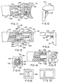
- the temple pieces 4 include a hinge block 6, which is hinged, in a conventional way, to the frame 3 at one end of the hinge block, one illustrative example of which is shown in Figure 1.
- a face of the hinge block abuts the frame 3, in a conventional way, to limit the outward rotation of the temple pieces with respect to the frame.
- a surface of the hinge block generally parallel to the frame-abutting face, faces a surface of a rotatable segment of the temple pieces.
- the hinge block 6 has on a surface 9 facing a rotatable segment 7 of the temple piece 4, a face plate 11, in an outer surface of which are dimples 12.
- the face plate 11 has a passage through a central part, through which a pin 13 extends.
- An outer end 13 of the pin 13 is fixed in the hinge block 6.
- the pin carries a head 18.
- the head end of the pin is mounted in a socket or well 10 in an end of the rotatable segment 7 of the temple piece along with a helical compression spring 19, caged between an underside of the head 18 and an inner surface of a temple segment plate 15 secured to the section 7.
- the temple segment plate 15 has projections 16 complementary to the dimples 12, in both size and location.
- the length of the spring 19 is such as to permit the rotatable segment 7 of the temple piece 4 to be retracted as shown in Figure 2, and permitted to be biased by the spring into a position at which the projections 16 seat in the dimples 9, thus restraining the rotatable segment 7 from accidental rotation.
- eyeglasses 41 have a frame 43, temples 44 and ear pieces 58.
- a temple block 46 is hingedly mounted on the frame 43.
- a rod 53 is anchored at one end in the block 46, and, at its other end, is provided with a head 61.
- a rotatable segment 47 is rotatably mounted on the rod 53.
- the rotatable segment 47 has at its end adjacent the ear piece a square socket or mortise 59 in the ear piece, a square tenon 57 of a size and shape complementary to inside surfaces of walls defining the socket 59, so as to seat within the socket 59.
- the rotating segment 47 has on it a tenon 56 which is shaped and sized complementarily to a socket, mortise or well 50 in the hinge block 46.
- a spring 65 is mounted on the rod 53 within the socket 59, and is caged between an under surface of the head 61 and an inner surface of an annular stop 63 that is press fitted or otherwise securely mounted within the socket 59.
- Figure 1 illustrates yet another form, in which a tongue and groove arrangement is used to accomplish the same object, in the case of the glasses shown in Figure 1, the tongue being provided on the hinge block 6 and the groove in the rotating segment of the temple piece 4.
- the locking devices shown in Figures 3A through 3E allow for different degrees of rotation: the rectangular arrangement of Figure 3A permitting only two positions, at 180° from one another, the triangular arrangement of Figure 3B permitting three degrees of rotation, 120° apart, the square tenon of Figure 3C permitting four degrees, 90° from one another, the rectangular mortise and tenon of Figure 3D permitting two degrees of rotation, and the cruciform mortise and tenon arrangement of Figure 3E permitting four.
- a pair of eyeglasses 71, with a frame 73, has temples 74, with hinge blocks 76, each with a rotatable segment 77, and ear pieces 78.
- the embodiment shown in Figure 5 is similar to that shown in Figure 2, except that the rotatable segment 77 can be given any of the cross-sectional configurations shown in Figures 7A through 7E, the mortise and tenon arrangement being appropriate to the particular configuration.
- the securing and releasing mechanism can be that of either of the embodiments shown in Figures 1 and 2.
- eyeglasses 81 are shown, with a frame 83, temples 84, hinge blocks 86 and a rotatable segment 87.
- This embodiment corresponds to the embodiment shown in Figure 4, with a rod 93, shown somewhat schematically.
- eyeglasses 101 are shown as having a frame 103, hinge blocks 106, ear pieces 108, and a rod 113.
- Rotatably mounted on the rod 113 are a series of segments 117, 118, 119, 120, 121 and 122, all independently rotatable, and all having some form of rotation inhibiting structure at each end, complementarily shaped and sized with respect to a contiguous piece, thereby providing a multiple combination of surfaces.
- reference numeral 121 indicates the eyeglass of this embodiment, with a frame 123 and a rotatable temple piece 124.
- the temple piece is mounted to the frame by means of a hinge 125, a central knuckle 138 of which has a part embedded in the frame.
- Upper and lower knuckles 126 and 127 are formed integral with a leaf 129.
- the leaf 129 has a center prong 130 with a Tee head 131.
- An upper prong 133 is spaced above the center prong 130 and a lower prong 134 is spaced below the center prong 130.
- a recess 136 is chamfered as shown at 137.
- a central cavity or blind passage 139 At the hinge end of the rotatable temple piece 124, is a central cavity or blind passage 139, with a radially inwardly extending interrupted rim 141, interrupted diametrically by a transverse slot 142 through it, the slot being perpendicular to the plane defined by the leaf 129.
- an upper prong-receiving channel 144 and a lower prong receiving channel 145 are positioned, when the temple piece is properly oriented, to receive the prongs 133 and 134 respectively.
- Channels 144 and 145 are defined in part by upper flexible wall 147 and lower flexible wall 149.
- Each of the flexible walls 147 and 149 has at its free end a downwardly extending rib 150, sized and positioned to snap into the recesses 136.
- the temple piece 124 can be mounted on the central prong 130 by turning it at right angles to its normal position, and slipping the Tee head 131 through the slot 132 into the central cavity 139. The temple piece 124 can then be oriented in its proper position as shown in Figures 9 through 12, and pushed toward the frame 123.
- the ribs 150 will be cammed outwardly by the chamfers 137, to permit them to ride over a flat surface of the prongs, until the ribs snap into the recesses 136.
- To rotate the temple pieces through 180° is only necessary to pull the temple piece until the ribs 150 are cammed out of the recesses 136 and the temple pieces brought to the position shown in Figure 11, when it can be turned and pushed back into place.
- the construction of the eyeglasses of this embodiment can be modified to accommodate three or four degrees of rotation.
- the ear piece of the temple can be made as shown in either Figure 2 or Figure 4, for example, to be properly oriented.
- eyeglasses 161 have a hinge 162, which can be similar to the hinges in the embodiments described heretofore.
- a hinge block 164 in this embodiment has two cavities, a first cavity 166 and a second cavity 170.
- the first cavity is defined by an end wall 167 contiguous the hinge, a side wall 168, an intermediate wall 169, a top wall 171, a bottom wall 172, and a plate 190.
- the second cavity 170 shares the intermediate wall, side wall 168, top and bottom walls 171 and 172, and plate 190.
- Ribs 173 depend from and extend along a free edge of the top and bottom walls 171 and 172, forming a restricted mouth of the second cavity.
- the intermediate wall has in it a shaft passage 174, through which a central shaft 184 of a temple piece 175 extends.
- the shaft 184 is in the form of a bolt with a head 185 and a threaded shaft that screws into an internally threaded hole in the temple piece 175, as shown in figure 13.
- the temple piece 175 in this embodiment is four sided. It has a head end 177 with a neck 179 and shoulders 180.
- the head end 177 is slotted to define four flexible fingers 178, spaced from and surrounding the central shaft 184, as shown in Figure 13.
- the neck 179 defines top grooves or seats 181, bottom grooves or seats 182 and side grooves or seats 183.
- the grooves are shaped and sized complementarily to the ribs 173.
- the head 177 is square in front elevation, and the second cavity is shaped and proportioned complementarily to the head.
- the shaft 184 has a spring 187 mounted around the shaft, caged between the head 185 and a surface of the intermediate wall 169.
- the hinge block is made as it appears in Figure 13.
- the temple piece is simply installed from the open side as shown, and the plate 190 is bonded to the surfaces of the end, top, bottom and intermediate walls.
- the temple piece 175 can be pulled from the second cavity 170 by virtue of the flexing of the fingers 178, against the bias of the spring 187, until the head has cleared the mouth of the cavity. The temple piece can then be rotated through any desired increment of 90°, and snapped back into the cavity 170.
- temple piece and cavity 170 By changing the configuration of the temple piece and cavity 170, other configurations, either thinly rectangular for a two sided display, triangular, for a three sided display, or otherwise polygonal can be used.
- the spring 187 can be omitted.
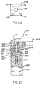
- eyeglasses 201 have a lense-holding frame 202, a hinge 205 and a hinge block 204 connected to a leaf of the hinge 205.
- the hinge block of 204 has a passage 207 extending from one end of the block to the other.
- the passage 207 has an open end 208 at the end of the block contiguous the frame 202 and the temple piece is in the position shown in Figure 21, and a more restricted opening 209 at its other end, has an annular shoulder 210.
- An outer surface 211 of the hinge block has in it dimples 212, arranged symmetrically about the opening 209.
- a temple piece 225 with a threaded bolt hole 224 has on a surface facing the outer surface 211, a series of projections 213 shaped and positioned to complementary to the dimples 212.
- a bolt 220 with a head 221 and a shank 222 threaded through at least the lower third of the shank has a helical spring 227 mounted on it between the head 221 and the shoulder 210, and is screwed into the threaded hold 224 to the degree of compression desired. If it is desired, for example, to preclude the rotation of the temple piece 225 it can be screwed down until the spring is compressed tightly against the shoulder 210.
- the compression of the spring 227 is just enough to prevent accidental rotation of the temple piece. It can be seen that any number of dimples 212 can be provided, and one or more projections 213, which would permit a multiplicity of positions of the temple piece, if that were desired.
- the temple piece 225 is square in cross section and the number oath of the dimples of the projections is four. This embodiment is the simplest of the constructions, and is readily manufactured.
- the rotatable segments of the temple pieces are indicia-carrying members.
- the indicia can be different materials, such as plastics, metals or wood, colors, shapes, graphic images, photographs, logos, trademarks, cartoons, or any other decorative feature, uniquely different on two or more surfaces.
- the temple pieces need not be retractable a substantial distance, particularly in the embodiments shown in Figures 2 ,4, and 21, where one or more spring loaded detents can be used, set into either the hinge block or the rotatable temple piece, in the case of the embodiment shown in Figure 2, or the hinge block or eyepiece or both, or the rotatable temple piece, in the case of the embodiment shown in Figure 4, in either case, with complementary dimples in the other member or members.
- Other detent means can be used, such as leaf springs or even resilient bumps made as part of the rotatable temple piece or hinge block. or ear piece as the case may be.
Claims (14)
- Brille aufweisend eine Brillenglas-tragende Fassung (3; 43; 73; 83; 103; 123; 202) und Bügelteile (4; 44; 74; 84; 117-122; 124; 175; 215), wobei die Bügelteile (4; 44; 74; 84; 117-122; 124; 175; 215) an einem Ende an der Fassung (3; 43; 73; 83; 103; 123; 202) befestigt sind und einen am Kopf anliegenden Teil (8; 58; 78; 88; 108) an einem anderen Ende aufweisen,
dadurch gekennzeichnet, dass diese entlang wenigstens eines der Bügelteile (4; 44; 74; 84; 117-122; 124; 175; 215) zwischen der Fassung (3; 43; 73; 83; 103; 123; 202) und dem am Kopf anliegenden Teil (8; 58; 78; 88; 108) Kennzeichen-tragende Mittel (7; 47; 77; 87; 117-122; 175; 225) umfasst, wobei die Kennzeichen-tragenden Mittel (7; 47; 77; 87; 117-122; 175; 225) einzelne Bereiche aufweisen, die verschiedene Kennzeichen tragen, und
die Kennzeichen-tragenden Mittel (7; 47; 77; 87; 117-122; 175; 225) in Bezug auf die Fassung (3; 43; 73; 83; 103; 123; 202) um eine Achse, die im Wesentlichen parallel zu dem Bügelteil (4; 44; 74; 84; 117-122; 124; 175; 215) ist, drehbar sind, um selektiv eins aus einer Mehrzahl der Kennzeichen zu zeigen. - Brille nach Anspruch 1,
dadurch gekennzeichnet, dass das Kennzeichen-tragende Mittel (7; 47; 77; 87; 117-122; 175; 225) in einen Teil des Bügelteils (4; 44; 74; 84; 117-122; 124; 175; 215) integriert ist. - Brille nach Anspruch 1,
dadurch gekennzeichnet, dass das Bügelteil (44) einen Stab (53) umfasst, der an einem Ende in einem Block (46) befestigt ist, welcher an der Fassung (43) gelenkig angebracht ist, wobei das Kennzeichen-tragende Mittel (47) ein Segment (47) ist, welches drehbar an dem Stab (53) befestigt ist, und das drehbare Segment (47) Mittel (56) zur Halterung des Kennzeichen-tragenden Mittels (47) in einer ausgewählten Orientierung gegen Drehung aufweist. - Brille nach Anspruch 1,
dadurch gekennzeichnet, dass die Kennzeichen Farben sind. - Brille nach Anspruch 1,
dadurch gekennzeichnet, dass die Kennzeichen unterschiedliche Materialien sind. - Brille nach Anspruch 1,
dadurch gekennzeichnet, dass die Kennzeichen unterschiedliche graphische Bilder sind. - Brille nach Anspruch 1,
dadurch gekennzeichnet, dass die Kennzeichen unterschiedliche Formen sind. - Brille nach Anspruch 1,
dadurch gekennzeichnet, dass die Kennzeichen-tragenden Mittel (117-122) eine Mehrzahl von unabhängig drehbaren Segmenten (117-122) umfassen. - Brille nach Anspruch 8,
dadurch gekennzeichnet, dass die Kennzeichen-tragenden Mittel (117-122) drehbar an einem Stab (113) befestigt sind, der in einem Bügelblock (106) verankert ist, der an der Fassung (103) gelenkig angebracht ist, und jedes der Segmente (117-122) Mittel zur Halterung der Segmente (117-122) in einer ausgewählten Orientierung in Bezug auf ein benachbartes Segment (117-122) trägt. - Brille nach Anspruch 1,
dadurch gekennzeichnet, dass diese ein Scharnier (125) zwischen dem Bügelteil (124) und der Fassung (123) umfasst, wobei das Scharnier (125) erste Gelenkmittel (138) aufweist, die an der Fassung (123) befestigt sind, und zweite Gelenkmittel (126, 127), die einen Flügel (129) mit einem zentralen Zinkenelement (130) mit einem Kopf (131), und äußeren Zinkenelementen (133, 134), die von dem zentralen Zinkenelement (130) beabstandet und parallel dazu sind, aufweisen, wobei das Bügelteil (124) eine zentrale Zinken-aufnehmende Kavität (139) und obere und untere äußere Zinken-aufnehmende Kavitäten (144, 145) aufweist, wobei die äußeren Zinkenelemente (133, 134) jedes eine Ausnehmung (136) aufweisen und die flexiblen Wandungen einen sich einwärts erstreckenden Steg (150) aufweisen, welcher ausgebildet ist, um in die Ausnehmung (136) zu passen. - Brille nach Anspruch 1,
dadurch gekennzeichnet, dass die Bügelteile (4; 44; 74; 84; 117-122; 124; 175; 215) eine Mehrzahl sich in Längsrichtung erstreckender zueinander winkliger Oberflächen aufweisen und unterschiedliche Kennzeichen zwischen der Fassung (3; 43; 73; 83; 103; 123; 202) und dem am Kopf anliegenden Teil (8; 58; 78; 88; 108) tragen, wobei die Bügelteile (4; 44; 74; 84; 117-122; 124; 175; 215) drehbar an der Fassung (3; 43; 73; 83; 103; 123; 202) befestigt sind, um die Kennzeichen selektiv zu zeigen. - Brille nach Anspruch 11,
dadurch gekennzeichnet, dass diese Mittel (16; 56; 76; 86; 106; 129; 177; 204) umfasst, die das Bügelteil (4; 44; 74; 84; 117-122; 124; 175; 215) wirksam an unbeabsichtigter Drehung hindern. - Brille nach Anspruch 1,
dadurch gekennzeichnet, dass diese einen Scharnierblock (204), der an der Fassung (202) gelenkig angebracht ist, wobei das Bügelteil (215) an einem Ende an dem Scharnierblock (204) befestigt ist, wobei der Scharnierblock (204) einen Durchlass (207) mit einer Schulter (210) um einen begrenzten Teil (209) des Durchlasses (207) aufweist, einen Bolzen (220) mit einem Kopf (221) und einem Schaft (222), wobei wenigstens ein Teil dessen ein Gewinde aufweist und eine spiralförmige Feder (227), die an dem Schaft (222) befestigt ist und zwischen dem Kopf (221) und der Schulter (210) eingeschlossen ist, wobei der Schaft (222) in eine interne Gewindebohrung (224) in dem Bügelteil (215) eingedreht ist, wobei das Bügelteil (215) an dem Scharnierblock (204) befestigt ist, komplementäre Mittel (212, 213) auf dem Bügelteil (215) und dem Scharnierblock (204) zur Halterung des Bügelteils (215) in ausgewählter Orientierung in Bezug auf den Scharnierblock (204) und Kennzeichen entlang Oberflächen des Bügelteils (215) zwischen der Fassung (202) und dem am Kopf anliegenden Teil umfasst, wobei die Kennzeichen selektiv mit unterschiedlichen Orientierungen des Bügelteils (215) in Bezug auf den Scharnierblock (204) gezeigt werden. - Brille nach Anspruch 1,
dadurch gekennzeichnet, dass diese einen Schamierblock (204), der an der Fassung (202) gelenkig angebracht ist, wobei das Bügelteil (215) an einem Ende an dem Scharnierblock (204) drehbar befestigt ist, wobei das Bügelteil (215) oder der Scharnierblock (204) einen Durchlass (207) mit einer Schulter (210) um einen begrenzten Teil (209) des Durchlasses (207) aufweist, Befestigungsmittel (220), die einen Kopf (221) und einen Schaft (222) aufweisen, wobei der Kopf (221) in dem Durchlass (207) angeordnet ist und sich der Schaft (222) durch den begrenzten Teil (209) erstreckt und in dem Scharnierblock (204) oder dem Bügelteil (215) befestigt ist, in dem der Kopf (221) nicht befestigt ist, wobei das Bügelteil (215) an dem Scharnierblock (204) befestigt ist, wobei der Kopf (221) von der Schulter (210) um eine Distanz beabstandet ist, um das Zurückziehen des Bügelteils (215) von dem Schamierblock (204) und seine Drehung um den Schaft (222) in Bezug auf den Scharnierblock (204) zu erlauben, komplementäre Mittel (212, 213) auf dem Bügelteil (215) und dem Scharnierblock (204) zur Halterung des Bügelteils (215) in ausgewählter Orientierung in Bezug auf den Scharnierblock (204) und Kennzeichen entlang Oberflächen des Bügelteils (215) zwischen der Fassung (202) und dem am Kopf anliegenden Teil umfasst, wobei die Kennzeichen selektiv mit verschiedenen Orientierungen des Bügelteils (215) in Bezug auf den Scharnierblock (204) gezeigt werden.
Applications Claiming Priority (3)
| Application Number | Priority Date | Filing Date | Title |
|---|---|---|---|
| US08/651,271 US5652635A (en) | 1996-05-23 | 1996-05-23 | Decorative eyeglasses |
| PCT/US1997/004037 WO1997044699A1 (en) | 1996-05-23 | 1997-03-14 | Decorative eyeglasses |
| US651271 | 2003-08-28 |
Publications (3)
| Publication Number | Publication Date |
|---|---|
| EP0901648A1 EP0901648A1 (de) | 1999-03-17 |
| EP0901648A4 EP0901648A4 (de) | 1999-05-12 |
| EP0901648B1 true EP0901648B1 (de) | 2003-12-17 |
Family
ID=24612213
Family Applications (1)
| Application Number | Title | Priority Date | Filing Date |
|---|---|---|---|
| EP97915075A Expired - Lifetime EP0901648B1 (de) | 1996-05-23 | 1997-03-14 | Dekorative brillen |
Country Status (11)
| Country | Link |
|---|---|
| US (1) | US5652635A (de) |
| EP (1) | EP0901648B1 (de) |
| JP (1) | JP4122421B2 (de) |
| AT (1) | ATE256877T1 (de) |
| AU (1) | AU2211397A (de) |
| BR (1) | BR9709334A (de) |
| CA (1) | CA2256482A1 (de) |
| DE (1) | DE69726851T2 (de) |
| ES (1) | ES2213211T3 (de) |
| IL (1) | IL127191A0 (de) |
| WO (1) | WO1997044699A1 (de) |
Cited By (2)
| Publication number | Priority date | Publication date | Assignee | Title |
|---|---|---|---|---|
| WO2007147953A1 (fr) * | 2006-06-21 | 2007-12-27 | DENIS BUFFARD, Société par actions simplifiée | Branche de lunettes et lunettes comportant une telle branche |
| WO2011027043A1 (fr) | 2009-09-07 | 2011-03-10 | Killine Optical Ltd | Branche de lunettes pourvue d'un manchon de decoration rotatif et lunettes associees |
Families Citing this family (31)
| Publication number | Priority date | Publication date | Assignee | Title |
|---|---|---|---|---|
| US5886765A (en) * | 1996-11-25 | 1999-03-23 | Kirschner; Mitchell | Frame with decoration rotatably mounted on it |
| FR2777667A1 (fr) * | 1998-04-15 | 1999-10-22 | Patrick Lamy | Monture de lunettes modulable |
| FR2788862B1 (fr) * | 1999-01-25 | 2001-04-13 | Logo | Monture de lunettes |
| US6652093B1 (en) | 1999-04-15 | 2003-11-25 | Airess S.A. | Variable eyeglass frame |
| US6890073B2 (en) * | 2003-03-20 | 2005-05-10 | Liberty Sport, Inc. | Impact resistant eyewear frame assembly having a split frame |
| US7137700B2 (en) * | 2003-03-20 | 2006-11-21 | Liberty Sport, Inc. | Impact resistant eyewear frame assembly having a split frame and fastener reinforcement |
| US8142015B2 (en) * | 2003-10-28 | 2012-03-27 | Venetian Holdings, Llc. | Baby and toddler sunglasses |
| JP2006220966A (ja) * | 2005-02-10 | 2006-08-24 | Isao Ebara | メガネフレームおよびフレームカバー |
| US7637609B1 (en) * | 2006-02-24 | 2009-12-29 | Chic Optic, Inc. | Resilient hinge for eyeglasses |
| US7341342B2 (en) * | 2006-04-11 | 2008-03-11 | Anamika Jain | Eyeglasses |
| US8747466B2 (en) * | 2007-08-27 | 2014-06-10 | Amo Groningen, B.V. | Intraocular lens having extended depth of focus |
| US7559644B1 (en) * | 2008-02-07 | 2009-07-14 | Steve Lloyd | Eyeglass frame incorporating ornamented temple members |
| FR2931000A1 (fr) * | 2008-05-06 | 2009-11-13 | Marius Morel France Sas Soc Pa | Monture de lunettes avec element d'ornement pour branche de monture de lunettes |
| EP2457120B1 (de) * | 2009-07-20 | 2020-01-08 | Killine Optical Ltd | Bügel für brille und entsprechende brille |
| IT1396454B1 (it) * | 2009-10-14 | 2012-11-23 | Sgm S R L | Montatura per occhiali. |
| IT1397620B1 (it) * | 2009-10-23 | 2013-01-18 | Prada Sa | Asta per occhiali ed occhiali comprendenti quest'asta |
| FR2963441B1 (fr) * | 2010-07-29 | 2013-04-26 | Vuitton Louis Sa | Paire de lunettes a reglage telescopique |
| US8469508B2 (en) | 2010-09-23 | 2013-06-25 | Silver Global Manufacturing Llc | Decorative selectable arms with bayonet clip attachment of arms to eyeglass frames |
| WO2012093986A1 (en) * | 2011-01-04 | 2012-07-12 | Silver Global Manufacturing Llc | Decorative selectable arms with selectable ornaments for eyeglasses |
| US8317318B2 (en) | 2011-04-08 | 2012-11-27 | Silver Global Manufacturing Llc | Side arm release system for eyeglass frame with changeable temple pieces |
| US20120327358A1 (en) * | 2011-06-21 | 2012-12-27 | Nicola Iaria | Eyewear frame with discrete sections of particular characteristics |
| FR2982040B1 (fr) * | 2011-11-02 | 2013-11-15 | Richard Chene | Branche pivotante pour monture de lunettes |
| US9645415B2 (en) * | 2012-08-19 | 2017-05-09 | Tahirah Wilson | Adjustable optical device |
| GB2524297A (en) * | 2014-03-19 | 2015-09-23 | Sholly Inglis | A pair of spectacles |
| ITUB20150694A1 (it) * | 2015-05-18 | 2016-11-18 | Occhiali 2 0 S R L | Occhiali con aste regolabili |
| WO2017165796A1 (en) * | 2016-03-25 | 2017-09-28 | Clearvision Optical Co., Inc. | Eyeglass frames with replaceable temples |
| USD895000S1 (en) * | 2016-04-13 | 2020-09-01 | Carl H. Jones | Eye glasses |
| IT201700110470A1 (it) * | 2017-10-03 | 2019-04-03 | Mirage S P A | Astina per occhiali con anima assemblata |
| US11215843B2 (en) * | 2019-08-21 | 2022-01-04 | Warby Parker Inc. | Spinnable frames for spectacles |
| US11892643B2 (en) * | 2019-12-13 | 2024-02-06 | K-Tronics (Suzhou) Technology Co., Ltd. | Augmented reality glasses |
| CN111258086A (zh) * | 2020-03-18 | 2020-06-09 | 昆山众赢昌盛贸易有限公司 | 一种眼镜 |
Family Cites Families (10)
| Publication number | Priority date | Publication date | Assignee | Title |
|---|---|---|---|---|
| US1919731A (en) * | 1931-02-06 | 1933-07-25 | Kates Abraham | Spectacles |
| US3133141A (en) * | 1962-01-05 | 1964-05-12 | Sellstrom Mfg Company | Adjustable temple for eyeglasses |
| US3667834A (en) * | 1971-03-22 | 1972-06-06 | Mine Safety Appliances Co | Adjustable length temple for spectacles |
| US3981569A (en) * | 1974-12-16 | 1976-09-21 | Morgan J Robert | Eyeglass structure |
| US4564272A (en) * | 1983-03-18 | 1986-01-14 | Rinnooy Kan Edmond A | Eyeglasses with interchangeable parts |
| US4848889A (en) * | 1985-06-03 | 1989-07-18 | Satex Oil Corporation (Pty) Ltd. | Artcle of adornment |
| US4950066A (en) * | 1988-11-07 | 1990-08-21 | James Hartman | Eyeglasses having demountable functional and decorative elements |
| US5185620A (en) * | 1991-08-22 | 1993-02-09 | Cooper George F | Eyeglass system |
| US5321442A (en) * | 1992-02-25 | 1994-06-14 | Albanese Gerry M | Eyeglasses with detachable lenses, sidebars, and adjustable earpieces |
| DE9402319U1 (de) * | 1994-02-11 | 1994-04-14 | Nebl Lothar | Dekorsystem |
-
1996
- 1996-05-23 US US08/651,271 patent/US5652635A/en not_active Expired - Lifetime
-
1997
- 1997-03-14 DE DE69726851T patent/DE69726851T2/de not_active Expired - Fee Related
- 1997-03-14 BR BR9709334A patent/BR9709334A/pt not_active Application Discontinuation
- 1997-03-14 IL IL12719197A patent/IL127191A0/xx unknown
- 1997-03-14 EP EP97915075A patent/EP0901648B1/de not_active Expired - Lifetime
- 1997-03-14 ES ES97915075T patent/ES2213211T3/es not_active Expired - Lifetime
- 1997-03-14 AT AT97915075T patent/ATE256877T1/de not_active IP Right Cessation
- 1997-03-14 WO PCT/US1997/004037 patent/WO1997044699A1/en active IP Right Grant
- 1997-03-14 JP JP54232597A patent/JP4122421B2/ja not_active Expired - Fee Related
- 1997-03-14 CA CA002256482A patent/CA2256482A1/en not_active Abandoned
- 1997-03-14 AU AU22113/97A patent/AU2211397A/en not_active Abandoned
Cited By (3)
| Publication number | Priority date | Publication date | Assignee | Title |
|---|---|---|---|---|
| WO2007147953A1 (fr) * | 2006-06-21 | 2007-12-27 | DENIS BUFFARD, Société par actions simplifiée | Branche de lunettes et lunettes comportant une telle branche |
| FR2902898A1 (fr) * | 2006-06-21 | 2007-12-28 | Denis Buffard Soc Par Actions | Branche de lunettes et lunettes comportant une telle branche |
| WO2011027043A1 (fr) | 2009-09-07 | 2011-03-10 | Killine Optical Ltd | Branche de lunettes pourvue d'un manchon de decoration rotatif et lunettes associees |
Also Published As
| Publication number | Publication date |
|---|---|
| AU2211397A (en) | 1997-12-09 |
| DE69726851T2 (de) | 2004-11-04 |
| EP0901648A1 (de) | 1999-03-17 |
| CA2256482A1 (en) | 1997-11-27 |
| ES2213211T3 (es) | 2004-08-16 |
| US5652635A (en) | 1997-07-29 |
| JP4122421B2 (ja) | 2008-07-23 |
| EP0901648A4 (de) | 1999-05-12 |
| WO1997044699A1 (en) | 1997-11-27 |
| ATE256877T1 (de) | 2004-01-15 |
| JP2001503870A (ja) | 2001-03-21 |
| BR9709334A (pt) | 1999-08-10 |
| DE69726851D1 (de) | 2004-01-29 |
| IL127191A0 (en) | 1999-09-22 |
Similar Documents
| Publication | Publication Date | Title |
|---|---|---|
| EP0901648B1 (de) | Dekorative brillen | |
| US4153347A (en) | Eyeglass frames with removable, interchangeable lenses, rims and temple pieces | |
| US8608309B2 (en) | Eyeglass system | |
| US6918667B1 (en) | Auxiliary eyewear attachment apparatus | |
| KR20070007147A (ko) | 안경 | |
| US5532767A (en) | Pantoscopic and length adjustable safety spectacle | |
| US20040057009A1 (en) | Coupling system for securing a one-piece lens to temples | |
| US20170184872A1 (en) | Interchangeable Eyeglass Lens Rim Using Magnetic Retaining Forces | |
| JP2006039511A (ja) | 複合用途対応型眼鏡 | |
| US20170068115A1 (en) | Decorative attachment for eyewear temple | |
| GB2573359A (en) | Spectacles | |
| US6655799B1 (en) | Clip-on lenses | |
| US7753519B2 (en) | Temples for eyeglasses | |
| CA2271039A1 (en) | Changeable frame design | |
| US4848889A (en) | Artcle of adornment | |
| US5044741A (en) | Eyeglasses with integral rear view mirror | |
| CN212135081U (zh) | 可伸缩镜腿的眼镜 | |
| MXPA98009801A (en) | Anteojos decorati | |
| US6776481B2 (en) | Clip on visor | |
| KR890003980B1 (ko) | 다도수 또는 다색 방향전환 다목적 안경 | |
| US20030063253A1 (en) | Vision facilitation apparatus and method | |
| KR200284244Y1 (ko) | 모자 부착 겸용 안경 세트 | |
| US20200271952A1 (en) | Interchangeable eyewear system | |
| KR950000219Y1 (ko) | 썬그라스 부착 모자 | |
| KR200210352Y1 (ko) | 안경코 |
Legal Events
| Date | Code | Title | Description |
|---|---|---|---|
| PUAI | Public reference made under article 153(3) epc to a published international application that has entered the european phase |
Free format text: ORIGINAL CODE: 0009012 |
|
| 17P | Request for examination filed |
Effective date: 19981118 |
|
| AK | Designated contracting states |
Kind code of ref document: A1 Designated state(s): AT BE CH DE DK ES FI FR GB GR IE IT LI LU MC NL PT SE |
|
| A4 | Supplementary search report drawn up and despatched |
Effective date: 19990331 |
|
| AK | Designated contracting states |
Kind code of ref document: A4 Designated state(s): AT BE CH DE DK ES FI FR GB GR IE IT LI LU MC NL PT SE |
|
| 17Q | First examination report despatched |
Effective date: 20020731 |
|
| GRAH | Despatch of communication of intention to grant a patent |
Free format text: ORIGINAL CODE: EPIDOS IGRA |
|
| GRAS | Grant fee paid |
Free format text: ORIGINAL CODE: EPIDOSNIGR3 |
|
| GRAA | (expected) grant |
Free format text: ORIGINAL CODE: 0009210 |
|
| AK | Designated contracting states |
Kind code of ref document: B1 Designated state(s): AT BE CH DE DK ES FI FR GB GR IE IT LI LU MC NL PT SE |
|
| PG25 | Lapsed in a contracting state [announced via postgrant information from national office to epo] |
Ref country code: NL Free format text: LAPSE BECAUSE OF FAILURE TO SUBMIT A TRANSLATION OF THE DESCRIPTION OR TO PAY THE FEE WITHIN THE PRESCRIBED TIME-LIMIT Effective date: 20031217 Ref country code: LI Free format text: LAPSE BECAUSE OF FAILURE TO SUBMIT A TRANSLATION OF THE DESCRIPTION OR TO PAY THE FEE WITHIN THE PRESCRIBED TIME-LIMIT Effective date: 20031217 Ref country code: FI Free format text: LAPSE BECAUSE OF FAILURE TO SUBMIT A TRANSLATION OF THE DESCRIPTION OR TO PAY THE FEE WITHIN THE PRESCRIBED TIME-LIMIT Effective date: 20031217 Ref country code: CH Free format text: LAPSE BECAUSE OF FAILURE TO SUBMIT A TRANSLATION OF THE DESCRIPTION OR TO PAY THE FEE WITHIN THE PRESCRIBED TIME-LIMIT Effective date: 20031217 Ref country code: BE Free format text: LAPSE BECAUSE OF FAILURE TO SUBMIT A TRANSLATION OF THE DESCRIPTION OR TO PAY THE FEE WITHIN THE PRESCRIBED TIME-LIMIT Effective date: 20031217 Ref country code: AT Free format text: LAPSE BECAUSE OF FAILURE TO SUBMIT A TRANSLATION OF THE DESCRIPTION OR TO PAY THE FEE WITHIN THE PRESCRIBED TIME-LIMIT Effective date: 20031217 |
|
| REG | Reference to a national code |
Ref country code: GB Ref legal event code: FG4D |
|
| REG | Reference to a national code |
Ref country code: CH Ref legal event code: EP |
|
| REG | Reference to a national code |
Ref country code: IE Ref legal event code: FG4D |
|
| REF | Corresponds to: |
Ref document number: 69726851 Country of ref document: DE Date of ref document: 20040129 Kind code of ref document: P |
|
| PG25 | Lapsed in a contracting state [announced via postgrant information from national office to epo] |
Ref country code: LU Free format text: LAPSE BECAUSE OF NON-PAYMENT OF DUE FEES Effective date: 20040314 |
|
| PG25 | Lapsed in a contracting state [announced via postgrant information from national office to epo] |
Ref country code: IE Free format text: LAPSE BECAUSE OF NON-PAYMENT OF DUE FEES Effective date: 20040315 |
|
| PGFP | Annual fee paid to national office [announced via postgrant information from national office to epo] |
Ref country code: DE Payment date: 20040316 Year of fee payment: 8 Ref country code: GB Payment date: 20040316 Year of fee payment: 8 |
|
| PG25 | Lapsed in a contracting state [announced via postgrant information from national office to epo] |
Ref country code: SE Free format text: LAPSE BECAUSE OF FAILURE TO SUBMIT A TRANSLATION OF THE DESCRIPTION OR TO PAY THE FEE WITHIN THE PRESCRIBED TIME-LIMIT Effective date: 20040317 Ref country code: GR Free format text: LAPSE BECAUSE OF FAILURE TO SUBMIT A TRANSLATION OF THE DESCRIPTION OR TO PAY THE FEE WITHIN THE PRESCRIBED TIME-LIMIT Effective date: 20040317 Ref country code: DK Free format text: LAPSE BECAUSE OF FAILURE TO SUBMIT A TRANSLATION OF THE DESCRIPTION OR TO PAY THE FEE WITHIN THE PRESCRIBED TIME-LIMIT Effective date: 20040317 |
|
| PGFP | Annual fee paid to national office [announced via postgrant information from national office to epo] |
Ref country code: FR Payment date: 20040319 Year of fee payment: 8 |
|
| PGFP | Annual fee paid to national office [announced via postgrant information from national office to epo] |
Ref country code: ES Payment date: 20040322 Year of fee payment: 8 |
|
| PG25 | Lapsed in a contracting state [announced via postgrant information from national office to epo] |
Ref country code: MC Free format text: LAPSE BECAUSE OF NON-PAYMENT OF DUE FEES Effective date: 20040331 |
|
| NLV1 | Nl: lapsed or annulled due to failure to fulfill the requirements of art. 29p and 29m of the patents act | ||
| REG | Reference to a national code |
Ref country code: CH Ref legal event code: PL |
|
| REG | Reference to a national code |
Ref country code: ES Ref legal event code: FG2A Ref document number: 2213211 Country of ref document: ES Kind code of ref document: T3 |
|
| ET | Fr: translation filed | ||
| PLBE | No opposition filed within time limit |
Free format text: ORIGINAL CODE: 0009261 |
|
| STAA | Information on the status of an ep patent application or granted ep patent |
Free format text: STATUS: NO OPPOSITION FILED WITHIN TIME LIMIT |
|
| 26N | No opposition filed |
Effective date: 20040920 |
|
| REG | Reference to a national code |
Ref country code: IE Ref legal event code: MM4A |
|
| PG25 | Lapsed in a contracting state [announced via postgrant information from national office to epo] |
Ref country code: IT Free format text: LAPSE BECAUSE OF NON-PAYMENT OF DUE FEES Effective date: 20050314 Ref country code: GB Free format text: LAPSE BECAUSE OF NON-PAYMENT OF DUE FEES Effective date: 20050314 |
|
| PG25 | Lapsed in a contracting state [announced via postgrant information from national office to epo] |
Ref country code: ES Free format text: LAPSE BECAUSE OF NON-PAYMENT OF DUE FEES Effective date: 20050315 |
|
| PG25 | Lapsed in a contracting state [announced via postgrant information from national office to epo] |
Ref country code: DE Free format text: LAPSE BECAUSE OF NON-PAYMENT OF DUE FEES Effective date: 20051001 |
|
| GBPC | Gb: european patent ceased through non-payment of renewal fee |
Effective date: 20050314 |
|
| PG25 | Lapsed in a contracting state [announced via postgrant information from national office to epo] |
Ref country code: FR Free format text: LAPSE BECAUSE OF NON-PAYMENT OF DUE FEES Effective date: 20051130 |
|
| REG | Reference to a national code |
Ref country code: FR Ref legal event code: ST Effective date: 20051130 |
|
| REG | Reference to a national code |
Ref country code: ES Ref legal event code: FD2A Effective date: 20050315 |
|
| PG25 | Lapsed in a contracting state [announced via postgrant information from national office to epo] |
Ref country code: PT Free format text: LAPSE BECAUSE OF NON-PAYMENT OF DUE FEES Effective date: 20040517 |