EP0900985A1 - Verfahren zum Kühlen einer Garofentür und Garofen mit Kühleinrichtung - Google Patents
Verfahren zum Kühlen einer Garofentür und Garofen mit Kühleinrichtung Download PDFInfo
- Publication number
- EP0900985A1 EP0900985A1 EP98116296A EP98116296A EP0900985A1 EP 0900985 A1 EP0900985 A1 EP 0900985A1 EP 98116296 A EP98116296 A EP 98116296A EP 98116296 A EP98116296 A EP 98116296A EP 0900985 A1 EP0900985 A1 EP 0900985A1
- Authority
- EP
- European Patent Office
- Prior art keywords
- door
- pane
- cooling air
- cooling
- muffle
- Prior art date
- Legal status (The legal status is an assumption and is not a legal conclusion. Google has not performed a legal analysis and makes no representation as to the accuracy of the status listed.)
- Granted
Links
- 238000001816 cooling Methods 0.000 title claims abstract description 113
- 238000000034 method Methods 0.000 title claims description 14
- 238000010411 cooking Methods 0.000 claims abstract description 29
- 238000004140 cleaning Methods 0.000 claims description 9
- 238000010438 heat treatment Methods 0.000 claims description 4
- 238000000197 pyrolysis Methods 0.000 description 7
- 238000009413 insulation Methods 0.000 description 5
- 125000006850 spacer group Chemical group 0.000 description 5
- 239000011521 glass Substances 0.000 description 4
- 238000009833 condensation Methods 0.000 description 3
- 230000005494 condensation Effects 0.000 description 3
- 239000007789 gas Substances 0.000 description 3
- 239000000853 adhesive Substances 0.000 description 2
- 230000001070 adhesive effect Effects 0.000 description 2
- 239000007788 liquid Substances 0.000 description 2
- 230000005855 radiation Effects 0.000 description 2
- 230000000630 rising effect Effects 0.000 description 2
- 235000002918 Fraxinus excelsior Nutrition 0.000 description 1
- 239000002956 ash Substances 0.000 description 1
- 230000015572 biosynthetic process Effects 0.000 description 1
- 238000004891 communication Methods 0.000 description 1
- 230000001419 dependent effect Effects 0.000 description 1
- 238000011161 development Methods 0.000 description 1
- 230000018109 developmental process Effects 0.000 description 1
- 230000000694 effects Effects 0.000 description 1
- 239000003517 fume Substances 0.000 description 1
- 239000002241 glass-ceramic Substances 0.000 description 1
- 238000004519 manufacturing process Methods 0.000 description 1
- 239000000463 material Substances 0.000 description 1
- 239000002184 metal Substances 0.000 description 1
- 229910044991 metal oxide Inorganic materials 0.000 description 1
- 150000004706 metal oxides Chemical class 0.000 description 1
- 230000000149 penetrating effect Effects 0.000 description 1
- 238000003860 storage Methods 0.000 description 1
- 230000035882 stress Effects 0.000 description 1
- 230000008646 thermal stress Effects 0.000 description 1
Images


Classifications
-
- F—MECHANICAL ENGINEERING; LIGHTING; HEATING; WEAPONS; BLASTING
- F24—HEATING; RANGES; VENTILATING
- F24C—DOMESTIC STOVES OR RANGES ; DETAILS OF DOMESTIC STOVES OR RANGES, OF GENERAL APPLICATION
- F24C15/00—Details
- F24C15/006—Arrangements for circulation of cooling air
-
- F—MECHANICAL ENGINEERING; LIGHTING; HEATING; WEAPONS; BLASTING
- F24—HEATING; RANGES; VENTILATING
- F24C—DOMESTIC STOVES OR RANGES ; DETAILS OF DOMESTIC STOVES OR RANGES, OF GENERAL APPLICATION
- F24C15/00—Details
- F24C15/02—Doors specially adapted for stoves or ranges
- F24C15/04—Doors specially adapted for stoves or ranges with transparent panels
Definitions
- the invention relates to a method for cooling a oven door and a oven.
- pyrolytic Self-cleaning pyrolysis of the oven muffle known which heats the interior of the muffle to temperatures of up to about 500 ° C and the cooking residues in easily removable Ashes are converted. Because of the high temperatures special measures are required for pyrolytic self-cleaning be taken to the oven door (oven door) at the front that people can come into contact with even during pyrolysis at a critical temperature to keep.
- the oven door usually has an inner pane facing the muffle and an outer pane applied by the muffle each made of glass. To even during a pyrolytic Self-cleaning sufficiently low temperatures at the To ensure the outer pane are generally in the Door between the inner pane and the outer pane or several additional washers for thermal Insulation used and the outside of the muffle and the Door are forced by convection of a cooling fan chilled.
- EP 0 583 180 A1 discloses a household cooking oven with an oven muffle and with a door for closing the loading opening of the oven muffle.
- the door has an inner pane, an intermediate pane and an outer pane, which are held in a door frame.
- a cooling fan is arranged above the oven muffle, which draws in fresh cooling air from an outside space in a suction area under the oven muffle and guides it around the oven muffle and blows it back into the outside space in a blow-out area above the door.
- the door Above the suction area, the door has air inlet openings in the frame floor and air outlet openings below the blow-out area.
- the invention is based on the object, a muffle door of the aforementioned type, particularly in pyrolysis operation, to cool efficiently.
- the invention is based on the consideration that at least one Washer from an air flow in one practical flow around the closed path so that the Air flow is not divided into two parallel air flows but an air flow first at one Flows along side of the washer and then on the side facing away from this side at least flows almost in the opposite direction. Thereby the door can be cooled with high efficiency and over a large pressure range (performance of the cooling device) an even air flow can be generated.
- this is a first advantageous embodiment characterized in that the cooling air is initially by the between the inner pane and the washer inner space and then through the between the intermediate disc and the outer disc formed outer Intermediate space is directed.
- Cooling air first through the outer space between the washer and the outer washer and then through the inner space between the inner pane and the washer is passed.
- the cooling can now only be provided for the door. It can also use other parts of the oven from the cooling air can be detected.
- the cooling air after flowing around the Guide the washer out of the door and around at least part of the oven muffle passed to also to cool the area around the oven muffle. Then will the cooling air preferably in one or more blow-out areas headed back into the outside space. At least one Blow-out area is then in an advantageous embodiment in an upper area of the door or above the door arranged.
- the cooling air can also flow around the washer led out of the door in a lower area of the door become.
- a preferred application is door cooling according to Invention in the pyrolytic self-cleaning of the muffle, at which particularly high temperatures occur.
- the intermediate disk protrudes below in the suction area than the inner pane.
- the intermediate disk protrudes below in the suction area than the inner pane.
- the outer pane, the inner pane and each washer are each at least in a preferred embodiment partly optically transparent to give an insight into to enable the muffle interior.
- the cooler generally comprises at least one Cooling fan, which is located either outside the door and with the outlet openings of the door via at least one Flow channel is connected, or in the door itself can be arranged.
- FIG. 1 is a household oven in a side Section shown with a muffle 10, a door 9 to close a loading opening 16 of the furnace muffle 10 and a housing 83. Above the furnace muffle 10 a cooling fan (cooling device) 23 is arranged. In one A blow-out area 37 is provided in the upper area of the door 9 and a suction area 36 is formed below the door 9.
- connection 84 provided via the vapors W from the muffle interior 15 is discharged into the air duct 75 and together with the cooling air K from the blow-out area 37 is blown out.
- the vapor W can also be diverted to another location and are not supplied to the cooling air K, for example with a built-in cooker via the associated built-in hob.
- the door 9 has an inner pane 2 and an outer pane 3 and one between the inner pane 2 and the outer pane 3 arranged washer 4.
- the intermediate disc 4 and the outer disc 3 are preferably parallel spaced from each other and can also be arranged at an angle to each other be. As a result, there are between the inner pane 2 and the intermediate pane 4 an inner space 24 and between the Outer pane 3 and the washer 4 an outer space 34 formed.
- an intermediate washer 4 can also consist of several panes Intermediate washers are provided.
- an air baffle 98 is provided in the door 9, said Spaces 24 and 34 from the air duct 75 and the blow-out area 37 for the cooling air K and Wrasen W separates.
- This air guide 98 can in particular be an air baffle that lies tightly against the inner pane 2. Between the air guide 98 and the intermediate slide 4, a connection area 38 is formed, via which the inner space 24 and the outer space 34 the door 9 are in flow connection.
- Air outlet area (air gap) 35 formed over which the Connection area 38 is connected to the outside space.
- This Air outlet area 35 can in particular between approximately 2 mm and about 6 mm high.
- the air baffle 98 is preferably slightly advanced in front of the outer pane 3 a flow dynamic influencing of the door interior in the air outlet area 35 emerging air through the emerging in the blow-out area 37 above the air guide 98 To prevent cooling air K at least largely. This can still be supported by using the blowout area or areas 37 for the cooling air K over the side of the door arranges offset to the air outlet area 35.
- the inner space 24 and the outer space 34 are each closed at the side and stand at their respective lower end with the suction area 36 in flow communication.
- the outer intermediate space 34 opens out closer to the suction area 36 than the inner space 24. This is achieved by facing the inner pane 2 the washer 4 is displaced upwards, for example around 15 mm to 30 mm and preferably between about 20 mm and 25 mm.
- the outer pane 3 can also do something be formed longer down than the washer 4, for example by a few millimeters. Through this Measures is the intake pressure, which is with the cooling fan running 23 acts in the suction area 36, at the lower mouth of the inner space 24 is not as large as at the lower Mouth of the outer space 34.
- the domestic oven has a pyrolytic self-cleaning function has, is on a door handle 21 of the door 9 a locking bolt 22 for locking the door 9 during of the pyrolysis operation provided in a, not shown Lock engages.
- the inner pane 2 and / or the intermediate disc 4 with a heat radiation reflecting Layer, for example one Metal oxide to be coated to the heat radiation in the Reflect back muffle interior 19.
- the Inner pane 2, intermediate pane 4 and the outer pane 3 generally consist of at least partially transparent (optically transparent) material, for example Glass or a glass ceramic, so that in the door 9 Viewing window is formed in the muffle interior 15, and are preferably rectangular in shape, with the inner pane 2 generally smaller than the outer pane 3 is.
- the two Carrier elements 5 and 6 each have a columnar shape Middle part 51 or 61 and two laterally from the middle part 51 and 61 protruding flange edges 50 and 60 on and can be formed in particular from U-shaped profiled sheet metal be.
- the adhesive connection ensures moreover a gentle connection of the carrier elements 5 and 6 with the outer pane 3 during manufacture.
- it can also a screw connection, a snap connection or another connection of the carrier elements 5 and 6 with the Outer pane 3 may be provided.
- a door handle 21 is attached to the carrier elements 5 and 6.
- each support element 5 and 6 (Fixing element) 7 or 8 for attaching the inner pane 2 releasable via at least one interlock switch 70 or 80 attached.
- the two holding elements 7 and 8 are each designed as angled rails, which run over the entire height of the inner pane 2.
- the inner pane 2 is between the two holding elements 7 and 8 and the one on the opposite Side of the inner pane 2 lying support surfaces 52 or 62 of the carrier elements 5 and 6 held.
- the two carrier elements 5 and 6 in their lower areas each have a receiving part 25 and 26 for the inner pane 2 attached, especially screwed, snapped or tense.
- the two receiving parts 25 and 26 exist preferably made of a plastic.
- Each of the bottom two Corners of the inner pane 2 is in a corresponding, angular area of the associated receiving part 25 or 26 fitted, the inner pane 2 on each corner is supported at the bottom and on a vertical stop and a horizontal stop and thereby to the In side, i.e. towards the oven muffle, and down in front of the Falling out is secured.
- the angular holding elements 7 and 8 are on the outer side surfaces of the carrier elements 5 and 6 each with the associated support elements 5 and 6 respectively in each case a locking switch 70 or 80 releasably connected.
- Each interlock switch 70 and 80 has one Operating handle 71 or 81 and is with this operating handle 71 and 81 can be moved axially (linearly). In a first end position of the operating handle 71 or 81 the associated locking switch 70 or 80 is locked and unlocked in the other end position. In the locked position of the lock switch 70 or 80 is the associated holding element 7 or 8 below a predetermined Contact pressure on the inner pane 2 and holds the Inner pane 2 fixed. The inner pane 2 should, however enough space to compensate for thermal expansion and avoiding thermal stresses are available. In the unlocked state of the locking switch 70 or 80 is the holding element 7 or 8 from the inner pane 2 detachable (removable).
- Receiving parts 25 and 26 is an opening 27 and 28 provided for carrying components for movement the door in particular door hinge or baking cart pull-out parts, which then into the internally hollow support element 5 or 6th inserted and locked there.
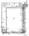
- the washer 4 is between the outer pane 3 and the inner pane 2 and between the two carrier elements 5 and 6 inserted into the door and preferably has inserted or sprayed on frame elements (frame parts, edge parts) 93 and 94 preferably made of plastic.
- frame elements 93 and 94 On the frame elements 93 and 94 are spacers 10, 12, 14, 16 and 18 for maintaining a distance between the washer 4 and the inner pane 2 on the one hand and on the opposite side spacers 11, 13, 15, 17 and 19 for maintaining a distance between the washer 4 and the outer pane 3 are provided.
- the spacers 12 to 17 on the frame members 93 and 94 can especially a convexly curved (round), preferably have a semicircular shape.
- the extreme in height Spacers 10 and 11 and 18 and 19 are for example paddle-shaped. With the spacers 18 and 19 of the The intermediate plate 4 lies on frame elements 93 and 94 a corresponding contact surface of the receiving part 25 and is supported downwards.
- the intermediate pane can now also be used 4, especially for cleaning purposes with the frame elements 93 and 94 easily removed from the door be, for example by slightly lifting and then pulling forward.
- FIG 1 flows around Cooling air K the washer 4 first inside and then Outside.
- FIGS. 3 and 4 each show one Embodiment in which the cooling air is the washer 4 flow around outside and then inside, the sense of flow is just turned over.
- connection area 38 is up and laterally also completed by the door frame 90.
- the panes 2 to 4 are framed in the door frame 90. Below are the two spaces 24 and 34 through the Washer 4 separated from each other.
- At least one suction opening is located in the door frame 90 at the bottom (Air inlet opening) 31, through the cooling air K from an outside space get into the outer space 34 of the door 9 can, and at least one outlet opening (air outlet opening) 32, through which through the door 9 and around the washer 4 flowed and designated K 'cooling air the inner space 24 can emerge from the door 9, educated.
- the at least one suction opening 31 is shown in FIG Embodiment arranged below. It can but also all or part of the suction openings on the Side of the door frame 90 and / or further up in the door frame Be 90.
- the suction opening (s) 31 and the exhaust opening (s) 32 can also again, as in the embodiment 1 and 2, through the downwardly open ends of the spaces 34 and 23 are formed in one after Door open at the bottom 9. Furthermore, the suction opening 31 and the blow-out opening 32 through a flow separating body 33, for example, a bent sheet, fluidically separated from each other.
- Cooling fan 22 For drawing cooling air K from the outside through the suction opening 31 is from a behind the oven muffle 10 in arranged in a lower area as part of a cooling device Cooling fan 22, which has a below the floor the flow channel 73 of the furnace muffle 10 with the or the blow openings 32 of the door 9 is connected, generates a negative pressure.
- Cooling fan 22 When switched on Cooling fan 22 is now through the suction opening 31st Cooling air K from the outside into the outside space 34 the door 9 sucked in via the connection area 38 in the inner space 24 and then out of the blow opening 32 led out into the flow channel 73.
- efficient cooling of the door 9 and in particular of its outer pane 3 its temperatures should be kept particularly low. Because it will the generally coldest air from the bottom of the outside space as cooling air K directly into the outer space 34 passed so that the outer pane 3 particularly is cooled well.
- Cooling air is denoted by K 'and is subsequently through the flow channel 73 from the cooling fan 22 in between the muffle rear wall 14 and the rear wall of the housing 85 of the housing 83 formed space 74 blown.
- the cooling air is thus in the embodiments described so far performed practically around the entire oven muffle 10 and thus ensures a spacious cooling of the Household oven.
- the cooling air can also, if one only wants to cool a part of the oven, for example limited to this sub-area for energy saving reasons be, especially only on a front Area of the oven, at least the door 9 and the other still the area of the control panel 92 with the temperature sensitive includes electronic components.
- a muffle insulation 19 (only partially in FIG. 3 shown).
- the cooling air K ' can also be located elsewhere, for example on the rear wall 85, as indicated by an arrow, be blown back into the outside space, for example up. Furthermore, a cooling fan 22 or 23 omitted if the other cooling fan 23 or 22 is dimensioned accordingly. Finally, one or the cooling fan in a special, not shown Embodiment in the door 9 itself in the flow path the cooling air can be arranged.
- the cooling air flow in the door 9 can instead of the previously described essentially vertical airflow also obliquely or horizontally or in a combination of at least guided two of the above directions through the door 9 then, the inlet and outlet openings accordingly are staggered.
Landscapes
- Engineering & Computer Science (AREA)
- Chemical & Material Sciences (AREA)
- Combustion & Propulsion (AREA)
- Mechanical Engineering (AREA)
- General Engineering & Computer Science (AREA)
- Electric Ovens (AREA)
Abstract
Description
- FIG 1
- einen Haushaltsgarofen in einem seitlichen Schnitt,
- FIG 2
- eine Ofenmuffeltür in einer Rückansicht und
- FIG 3 und 4
- einen Haushaltsgarofen in einem seitlichen Schnitt.
Claims (18)
- Verfahren zum Kühlen einer Tür (9) mit einer Außenscheibe (3), einer Innenscheibe (2) und wenigstens einer zwischen der Außenscheibe (3) und der Innenscheibe (2) angeordneten Zwischenscheibe (4),
wobeia) die Tür (9) eine Beschickungsöffnung (16) einer Garofenmuffel (10), deren Muffelinnenraum (15) erhitzt wird, verschließt,b) Kühlluft aus einem Außenraum in die Tür (9) geleitet wird undc) wenigstens ein Teil dieser Kühlluft wenigstens einmal um die wenigstens eine Zwischenscheibe (4) in der Tür (9) geleitet wird. - Verfahren nach Anspruch 1, bei dem die Kühlluft zunächst durch einen inneren Zwischenraum (24) zwischen der Innenscheibe (2) und der Zwischenscheibe (4) und anschließend durch einen äußeren Zwischenraum (34) zwischen der Zwischenscheibe (4) und der Außenscheibe (3) geleitet wird.
- Verfahren nach Anspruch 1, bei dem die Kühlluft zunächst durch einen äußeren Zwischenraum (34) zwischen der Zwischenscheibe (4) und der Außenscheibe (3) und anschließend durch einen inneren Zwischenraum (24) zwischen der Innenscheibe (2) und der Zwischenscheibe (4) geleitet wird.
- Verfahren nach einem der vorhergehenden Ansprüche, bei dem die Kühlluft nach Umströmen der Zwischenscheibe (4) wieder aus der Tür herausgeleitet und um wenigstens einen Teil der Ofenmuffel (10) geleitet wird.
- Verfahren nach einem der vorhergehenden Ansprüche, bei dem die Kühlluft aus dem Außenraum in einem unteren Bereich der Tür (9) in die Tür (9) geleitet wird.
- Verfahren nach einem der vorhergehenden Ansprüche, bei dem die Kühlluft nach Umströmen der Zwischenscheibe (4) in einem unteren Bereich der Tür (9) wieder aus der Tür (9) herausgeleitet wird.
- Verfahren nach einem der vorangegangenen Ansprüche, bei dem der Muffelinnenraum (15) zur pyrolytischen Selbstreinigung erhitzt wird.
- Garofen, insbesondere Haushaltsgarofen, mita) einer Garofenmuffel (10) mit einem Muffelinnenraum (15), einer Beschickungsöffnung (16) und wenigstens einer Heizeinrichtung zum Erhitzen des Muffelinnenraums (15),b) einer Tür (9) zum Verschließen der Beschickungsöffnung (16) der Garofenmuffel (10), welche Tür (9) eine Außenscheibe (3), eine Innenscheibe (2) und wenigstens eine zwischen der Außenscheibe (3) und der Innenscheibe (2) angeordnete Zwischenscheibe (4) aufweistc) einer Kühleinrichtung (23), die in einem Betriebszustand Kühlluft aus einem Außenraum in die Tür (9) ansaugt und diese Kühlluft wenigstens einmal um die wenigstens eine Zwischenscheibe (4) lenkt.
- Garofen nach Anspruch 8, bei dem die Kühleinrichtung (23) die in die Tür (9) gesaugte Kühlluft zunächst durch einen inneren Zwischenraum (24) zwischen der Innenscheibe (2) und der Zwischenscheibe (4) und anschließend durch einen äußeren Zwischenraum (34) zwischen der Zwischenscheibe (4) und der Außenscheibe (3) leitet.
- Garofen nach Anspruch 8, bei dem die Kühleinrichtung (23) die Kühlluft zunächst durch einen äußeren Zwischenraum (34) zwischen der Zwischenscheibe (4) und der Außenscheibe (3) und anschließend durch einen inneren Zwischenraum (24) zwischen der Innenscheibe (2) und der Zwischenscheibe (4) leitet.
- Garofen nach einem der Ansprüche 8 bis 10, bei dem die Kühleinrichtung (23) die Kühlluft nach Umströmen der Zwischenscheibe (4) wieder aus der Tür herausleitet, um wenigstens einen Teil der Ofenmuffel (10) leitet und anschließend in wenigstens einem Ausblasbereich (37) wieder in den Außenraum ausbläst.
- Garofen nach Anspruch 11, bei dem der wenigstens eine Ausblasbereich (37) in einem oberen Bereich der Tür (9) oder oberhalb der Tür (9) angeordnet ist.
- Garofen nach einem der Ansprüche 8 bis 12, bei dem die Kühleinrichtung (23) die Kühlluft aus dem Außenraum durch wenigstens eine Einlaßöffnung (31) in einem unteren Bereich der Tür (9) in die Tür (9) leitet.
- Garofen nach einem der Ansprüche 8 bis 13, bei dem die Kühleinrichtung (23) die Kühlluft nach Umströmen der Zwischenscheibe (4) durch wenigstens eine, vorzugsweise in einem unteren Bereich der Tür (9) angeordnete, Auslaßöffnung (32) wieder aus der Tür (9) herausleitet.
- Garofen nach Anspruch 14, bei dem die Zwischenscheibe (4) sich weiter nach unten erstreckt als die Innenscheibe (2).
- Garofen nach einem der Ansprüche 8 bis 15, bei dem die Außenscheibe (4) und die Innenscheibe (3) und jede Zwischenscheibe (2) wenigstens teilweise optisch transparent sind.
- Garofen nach Anspruch 14 oder einem der auf Anspruch 14 mittelbar oder unmittelbar rückbezogenen Ansprüche, bei dem die Kühleinrichtung wenigstens ein Kühlgebläse (22) umfaßt, das außerhalb der Tür (9) angeordnet ist und mit den Auslaßöffnungen der Tür (9) über wenigstens einen Strömungskanal (73) verbunden ist.
- Garofen nach einem der Ansprüche 8 bis 17, bei dem die Kühleinrichtung wenigstens ein Kühlgebläse (22) umfaßt, das innerhalb der Tür (9) angeordnet ist.
Applications Claiming Priority (4)
| Application Number | Priority Date | Filing Date | Title |
|---|---|---|---|
| DE1997138601 DE19738601C1 (de) | 1997-09-04 | 1997-09-04 | Verfahren zum Kühlen der Außenumgebung einer Ofenmuffel |
| DE19738601 | 1997-09-04 | ||
| DE19802799 | 1998-01-26 | ||
| DE19802799 | 1998-01-26 |
Publications (2)
| Publication Number | Publication Date |
|---|---|
| EP0900985A1 true EP0900985A1 (de) | 1999-03-10 |
| EP0900985B1 EP0900985B1 (de) | 2003-05-14 |
Family
ID=26039666
Family Applications (1)
| Application Number | Title | Priority Date | Filing Date |
|---|---|---|---|
| EP98116296A Expired - Lifetime EP0900985B1 (de) | 1997-09-04 | 1998-08-28 | Verfahren zum Kühlen einer Garofentür und Garofen mit Kühleinrichtung |
Country Status (2)
| Country | Link |
|---|---|
| EP (1) | EP0900985B1 (de) |
| DE (1) | DE59808333D1 (de) |
Cited By (19)
| Publication number | Priority date | Publication date | Assignee | Title |
|---|---|---|---|---|
| EP1050718A3 (de) * | 1999-05-04 | 2002-04-03 | AEG Hausgeräte GmbH | Garofen mit Wrasenabführung und Frischluftbeimischung |
| DE10047016A1 (de) * | 2000-09-22 | 2002-04-18 | Aeg Hausgeraete Gmbh | Verfahren zum Kühlen einer Ofenmuffeltür und Garofen mit Kühlung |
| DE10202495A1 (de) * | 2002-01-23 | 2003-07-31 | Bsh Bosch Siemens Hausgeraete | Backofen mit Kühleinrichtung |
| EP1128133A3 (de) * | 2000-02-22 | 2003-11-12 | BSH Bosch und Siemens Hausgeräte GmbH | Backofengerät |
| DE10342762A1 (de) * | 2003-09-16 | 2005-04-21 | Bsh Bosch Siemens Hausgeraete | Gehäuseeinheit eines Gargeräts |
| EP1544547A1 (de) * | 2003-12-17 | 2005-06-22 | LG Electronics Inc. | Elektrischer Ofen mit Kühlanlage für Tür |
| EP1783432A1 (de) | 2004-04-12 | 2007-05-09 | Lg Electronics Inc. | Vorrichtung zum Kühlen eines Gargeräts |
| KR100719849B1 (ko) * | 2005-04-26 | 2007-05-18 | 엘지전자 주식회사 | 조리기기 |
| WO2007029172A3 (en) * | 2005-09-05 | 2007-06-07 | Arcelik As | A cooking device with cooled door of cooking chamber |
| FR2906873A1 (fr) * | 2006-10-05 | 2008-04-11 | Brandt Ind Sas | Four de cuisson ayant une hauteur de section de passage d'un flux d'air constante. |
| FR2906872A1 (fr) * | 2006-10-05 | 2008-04-11 | Brandt Ind Sas | Four de cuisson comprenant un dispositif de deflexion d'air. |
| EP2090831A1 (de) * | 2008-02-13 | 2009-08-19 | Electrolux Home Products Corporation N.V. | Backofentür |
| US20110186030A1 (en) * | 2007-03-29 | 2011-08-04 | Electrolux Home Products Corporation N.V. | Cooking oven and method for operating the same |
| EP2505924A1 (de) * | 2011-03-30 | 2012-10-03 | Electrolux Home Products Corporation N.V. | Herd mit einem Vorderrahmen und einer Herdtür, die an dem Vorderrahmen schwenkbar montiert ist |
| US20130019854A1 (en) * | 2011-07-21 | 2013-01-24 | Dongwan Lim | Oven door |
| US9074777B2 (en) | 2010-02-26 | 2015-07-07 | Electrolux Home Products Corporation N.V. | Oven door for a domestic cooking oven |
| EP1795811A3 (de) * | 2005-12-12 | 2015-10-14 | LG Electronics Inc. | Ofen |
| CN106108690A (zh) * | 2016-07-29 | 2016-11-16 | 杭州老板电器股份有限公司 | 一种带燃气灶的电烤箱 |
| WO2019091791A1 (de) * | 2017-11-13 | 2019-05-16 | BSH Hausgeräte GmbH | Haushaltsgargerät mit einem garraum |
Families Citing this family (4)
| Publication number | Priority date | Publication date | Assignee | Title |
|---|---|---|---|---|
| DE10307086A1 (de) | 2003-02-19 | 2004-09-09 | Electrolux Home Products Corporation N.V. | Garofen |
| CN101469878B (zh) * | 2007-12-26 | 2011-03-02 | 乐金电子(天津)电器有限公司 | 带有烤箱的微波炉 |
| KR102471491B1 (ko) * | 2018-04-26 | 2022-11-28 | 삼성전자주식회사 | 오븐 |
| KR20230174403A (ko) * | 2022-06-21 | 2023-12-28 | 엘지전자 주식회사 | 조리기기 |
Citations (3)
| Publication number | Priority date | Publication date | Assignee | Title |
|---|---|---|---|---|
| US3561423A (en) * | 1969-01-07 | 1971-02-09 | Westinghouse Electric Corp | Door structure for a self-cleaning oven |
| FR2655132A1 (fr) * | 1989-11-27 | 1991-05-31 | Merloni Elettrodomestici Spa | Dispositif de refroidissement de porte de four. |
| EP0583180A1 (de) | 1992-07-07 | 1994-02-16 | Société SCHOLTES | Kühlanlage für Tür eines Haushaltsbackofens |
-
1998
- 1998-08-28 DE DE59808333T patent/DE59808333D1/de not_active Expired - Lifetime
- 1998-08-28 EP EP98116296A patent/EP0900985B1/de not_active Expired - Lifetime
Patent Citations (3)
| Publication number | Priority date | Publication date | Assignee | Title |
|---|---|---|---|---|
| US3561423A (en) * | 1969-01-07 | 1971-02-09 | Westinghouse Electric Corp | Door structure for a self-cleaning oven |
| FR2655132A1 (fr) * | 1989-11-27 | 1991-05-31 | Merloni Elettrodomestici Spa | Dispositif de refroidissement de porte de four. |
| EP0583180A1 (de) | 1992-07-07 | 1994-02-16 | Société SCHOLTES | Kühlanlage für Tür eines Haushaltsbackofens |
Cited By (25)
| Publication number | Priority date | Publication date | Assignee | Title |
|---|---|---|---|---|
| EP1050718A3 (de) * | 1999-05-04 | 2002-04-03 | AEG Hausgeräte GmbH | Garofen mit Wrasenabführung und Frischluftbeimischung |
| EP1128133A3 (de) * | 2000-02-22 | 2003-11-12 | BSH Bosch und Siemens Hausgeräte GmbH | Backofengerät |
| DE10047016A1 (de) * | 2000-09-22 | 2002-04-18 | Aeg Hausgeraete Gmbh | Verfahren zum Kühlen einer Ofenmuffeltür und Garofen mit Kühlung |
| DE10047016B4 (de) * | 2000-09-22 | 2005-02-10 | AEG Hausgeräte GmbH | Garofen |
| DE10202495A1 (de) * | 2002-01-23 | 2003-07-31 | Bsh Bosch Siemens Hausgeraete | Backofen mit Kühleinrichtung |
| DE10342762A1 (de) * | 2003-09-16 | 2005-04-21 | Bsh Bosch Siemens Hausgeraete | Gehäuseeinheit eines Gargeräts |
| EP1544547A1 (de) * | 2003-12-17 | 2005-06-22 | LG Electronics Inc. | Elektrischer Ofen mit Kühlanlage für Tür |
| CN1310610C (zh) * | 2003-12-17 | 2007-04-18 | Lg电子株式会社 | 带有门冷却结构的电烤箱 |
| US7228857B2 (en) | 2003-12-17 | 2007-06-12 | Lg Electronics Inc. | Electric oven with door cooling structure |
| EP1783432A1 (de) | 2004-04-12 | 2007-05-09 | Lg Electronics Inc. | Vorrichtung zum Kühlen eines Gargeräts |
| US7431029B2 (en) | 2004-04-12 | 2008-10-07 | Lg Electronics Inc. | Cooling apparatus of cooking appliance |
| KR100719849B1 (ko) * | 2005-04-26 | 2007-05-18 | 엘지전자 주식회사 | 조리기기 |
| WO2007029172A3 (en) * | 2005-09-05 | 2007-06-07 | Arcelik As | A cooking device with cooled door of cooking chamber |
| EP1795811A3 (de) * | 2005-12-12 | 2015-10-14 | LG Electronics Inc. | Ofen |
| FR2906873A1 (fr) * | 2006-10-05 | 2008-04-11 | Brandt Ind Sas | Four de cuisson ayant une hauteur de section de passage d'un flux d'air constante. |
| EP1930662A3 (de) * | 2006-10-05 | 2012-09-05 | Brandt Industries | Brennofen mit einer Durchlassprofilhöhe für einen konstanten Luftstrom |
| FR2906872A1 (fr) * | 2006-10-05 | 2008-04-11 | Brandt Ind Sas | Four de cuisson comprenant un dispositif de deflexion d'air. |
| US20110186030A1 (en) * | 2007-03-29 | 2011-08-04 | Electrolux Home Products Corporation N.V. | Cooking oven and method for operating the same |
| EP2090831A1 (de) * | 2008-02-13 | 2009-08-19 | Electrolux Home Products Corporation N.V. | Backofentür |
| US9074777B2 (en) | 2010-02-26 | 2015-07-07 | Electrolux Home Products Corporation N.V. | Oven door for a domestic cooking oven |
| EP2505924A1 (de) * | 2011-03-30 | 2012-10-03 | Electrolux Home Products Corporation N.V. | Herd mit einem Vorderrahmen und einer Herdtür, die an dem Vorderrahmen schwenkbar montiert ist |
| US20130019854A1 (en) * | 2011-07-21 | 2013-01-24 | Dongwan Lim | Oven door |
| US9115903B2 (en) * | 2011-07-21 | 2015-08-25 | Lg Electronics Inc. | Oven door |
| CN106108690A (zh) * | 2016-07-29 | 2016-11-16 | 杭州老板电器股份有限公司 | 一种带燃气灶的电烤箱 |
| WO2019091791A1 (de) * | 2017-11-13 | 2019-05-16 | BSH Hausgeräte GmbH | Haushaltsgargerät mit einem garraum |
Also Published As
| Publication number | Publication date |
|---|---|
| DE59808333D1 (de) | 2003-06-18 |
| EP0900985B1 (de) | 2003-05-14 |
Similar Documents
| Publication | Publication Date | Title |
|---|---|---|
| EP0900985B1 (de) | Verfahren zum Kühlen einer Garofentür und Garofen mit Kühleinrichtung | |
| DE1679199A1 (de) | Selbstreinigender Gasofen | |
| EP2278227B1 (de) | Backofen | |
| DE4127389A1 (de) | Herd mit sensorgesteuerter pyrolyse | |
| DE2705395A1 (de) | Lueftungseinrichtung fuer kochgeraete, insbesondere fuer herde | |
| DE19705697C2 (de) | Haushaltsherd mit einer auf Glas abgedichteten Muffel | |
| DE19738601C1 (de) | Verfahren zum Kühlen der Außenumgebung einer Ofenmuffel | |
| EP1566594A1 (de) | Verfahren und eine Vorrichtung zum Be- und/oder Entlüften eines Garofens | |
| EP0947776B1 (de) | Garofen mit Kühleinrichtung | |
| EP0671591A1 (de) | Vorrichtung zum Abführen von Wrasen aus einem Backofen | |
| EP0900984A1 (de) | Verfahren zum Abführen von Garkondensat aus einer Ofenmuffel Garofen mit Mitteln zum Abführen von Garkondensat | |
| EP0115838B1 (de) | Gasbetriebener Mehrfunktionsbackofen | |
| EP0731318A1 (de) | Backofen | |
| DE4407084A1 (de) | Backofen | |
| EP0995951B1 (de) | Backofen mit Mitteln zur pyrolytischen Selbstreinigung | |
| EP0940631A1 (de) | Gargerät mit pyrolytischer Selbstreinigung | |
| DE19961785A1 (de) | Dunstabzugsvorrichtung | |
| EP2444738B1 (de) | Gargerät mit einem Backofen | |
| DE10219348B4 (de) | Gargerät | |
| DE19801585A1 (de) | Verfahren zum Kühlen der Außenumgebung einer Ofenmuffel und Garofen mit Kühleinrichtung | |
| DE19861077C5 (de) | Gargerät mit Backofendichtung | |
| DE8806276U1 (de) | Backofen | |
| EP2390581B1 (de) | Gargerät | |
| DE10220133B4 (de) | Energiesparende Gargerätetür mit niedriger Fronttemperatur | |
| DE2759706C2 (de) | Herd mit Luftführungskanälen |
Legal Events
| Date | Code | Title | Description |
|---|---|---|---|
| PUAI | Public reference made under article 153(3) epc to a published international application that has entered the european phase |
Free format text: ORIGINAL CODE: 0009012 |
|
| AK | Designated contracting states |
Kind code of ref document: A1 Designated state(s): DE FR GB IT |
|
| AX | Request for extension of the european patent |
Free format text: AL;LT;LV;MK;RO;SI |
|
| 17P | Request for examination filed |
Effective date: 19990304 |
|
| AKX | Designation fees paid |
Free format text: DE FR GB IT |
|
| 17Q | First examination report despatched |
Effective date: 20020131 |
|
| GRAH | Despatch of communication of intention to grant a patent |
Free format text: ORIGINAL CODE: EPIDOS IGRA |
|
| GRAH | Despatch of communication of intention to grant a patent |
Free format text: ORIGINAL CODE: EPIDOS IGRA |
|
| GRAA | (expected) grant |
Free format text: ORIGINAL CODE: 0009210 |
|
| RIN1 | Information on inventor provided before grant (corrected) |
Inventor name: SCHROEDER, WALTER Inventor name: GIESELMANN, HEINZ Inventor name: SCHNEIDER, KNUT Inventor name: VON DOBSCHUETZ, MANFRED Inventor name: STEINMAIER, GEORG Inventor name: POERNER, HARALD Inventor name: HILDNER, DIETMAR Inventor name: WAELZLEIN, KLAUS Inventor name: STAHLMANN, ROLF |
|
| AK | Designated contracting states |
Designated state(s): DE FR GB IT |
|
| REG | Reference to a national code |
Ref country code: GB Ref legal event code: FG4D Free format text: NOT ENGLISH |
|
| REF | Corresponds to: |
Ref document number: 59808333 Country of ref document: DE Date of ref document: 20030618 Kind code of ref document: P |
|
| PGFP | Annual fee paid to national office [announced via postgrant information from national office to epo] |
Ref country code: GB Payment date: 20030731 Year of fee payment: 6 |
|
| GBT | Gb: translation of ep patent filed (gb section 77(6)(a)/1977) |
Effective date: 20030724 |
|
| ET | Fr: translation filed | ||
| PLBE | No opposition filed within time limit |
Free format text: ORIGINAL CODE: 0009261 |
|
| STAA | Information on the status of an ep patent application or granted ep patent |
Free format text: STATUS: NO OPPOSITION FILED WITHIN TIME LIMIT |
|
| 26N | No opposition filed |
Effective date: 20040217 |
|
| PG25 | Lapsed in a contracting state [announced via postgrant information from national office to epo] |
Ref country code: GB Free format text: LAPSE BECAUSE OF NON-PAYMENT OF DUE FEES Effective date: 20040828 |
|
| GBPC | Gb: european patent ceased through non-payment of renewal fee |
Effective date: 20040828 |
|
| PG25 | Lapsed in a contracting state [announced via postgrant information from national office to epo] |
Ref country code: IT Free format text: LAPSE BECAUSE OF NON-PAYMENT OF DUE FEES;WARNING: LAPSES OF ITALIAN PATENTS WITH EFFECTIVE DATE BEFORE 2007 MAY HAVE OCCURRED AT ANY TIME BEFORE 2007. THE CORRECT EFFECTIVE DATE MAY BE DIFFERENT FROM THE ONE RECORDED. Effective date: 20050828 |
|
| PGFP | Annual fee paid to national office [announced via postgrant information from national office to epo] |
Ref country code: DE Payment date: 20130821 Year of fee payment: 16 |
|
| PGFP | Annual fee paid to national office [announced via postgrant information from national office to epo] |
Ref country code: FR Payment date: 20130823 Year of fee payment: 16 |
|
| REG | Reference to a national code |
Ref country code: DE Ref legal event code: R119 Ref document number: 59808333 Country of ref document: DE |
|
| REG | Reference to a national code |
Ref country code: DE Ref legal event code: R119 Ref document number: 59808333 Country of ref document: DE Effective date: 20150303 |
|
| REG | Reference to a national code |
Ref country code: FR Ref legal event code: ST Effective date: 20150430 |
|
| PG25 | Lapsed in a contracting state [announced via postgrant information from national office to epo] |
Ref country code: DE Free format text: LAPSE BECAUSE OF NON-PAYMENT OF DUE FEES Effective date: 20150303 |
|
| PG25 | Lapsed in a contracting state [announced via postgrant information from national office to epo] |
Ref country code: FR Free format text: LAPSE BECAUSE OF NON-PAYMENT OF DUE FEES Effective date: 20140901 |