EP0900953B1 - Screw and nut drive with scraping device - Google Patents
Screw and nut drive with scraping device Download PDFInfo
- Publication number
- EP0900953B1 EP0900953B1 EP98116855A EP98116855A EP0900953B1 EP 0900953 B1 EP0900953 B1 EP 0900953B1 EP 98116855 A EP98116855 A EP 98116855A EP 98116855 A EP98116855 A EP 98116855A EP 0900953 B1 EP0900953 B1 EP 0900953B1
- Authority
- EP
- European Patent Office
- Prior art keywords
- adapter
- nut
- spindle
- stripper
- drive according
- Prior art date
- Legal status (The legal status is an assumption and is not a legal conclusion. Google has not performed a legal analysis and makes no representation as to the accuracy of the status listed.)
- Expired - Lifetime
Links
Images


Classifications
-
- F—MECHANICAL ENGINEERING; LIGHTING; HEATING; WEAPONS; BLASTING
- F16—ENGINEERING ELEMENTS AND UNITS; GENERAL MEASURES FOR PRODUCING AND MAINTAINING EFFECTIVE FUNCTIONING OF MACHINES OR INSTALLATIONS; THERMAL INSULATION IN GENERAL
- F16H—GEARING
- F16H25/00—Gearings comprising primarily only cams, cam-followers and screw-and-nut mechanisms
- F16H25/18—Gearings comprising primarily only cams, cam-followers and screw-and-nut mechanisms for conveying or interconverting oscillating or reciprocating motions
- F16H25/20—Screw mechanisms
- F16H25/24—Elements essential to such mechanisms, e.g. screws, nuts
- F16H25/2418—Screw seals, wipers, scrapers or the like
-
- F—MECHANICAL ENGINEERING; LIGHTING; HEATING; WEAPONS; BLASTING
- F16—ENGINEERING ELEMENTS AND UNITS; GENERAL MEASURES FOR PRODUCING AND MAINTAINING EFFECTIVE FUNCTIONING OF MACHINES OR INSTALLATIONS; THERMAL INSULATION IN GENERAL
- F16H—GEARING
- F16H25/00—Gearings comprising primarily only cams, cam-followers and screw-and-nut mechanisms
- F16H25/18—Gearings comprising primarily only cams, cam-followers and screw-and-nut mechanisms for conveying or interconverting oscillating or reciprocating motions
- F16H25/20—Screw mechanisms
- F16H25/22—Screw mechanisms with balls, rollers, or similar members between the co-operating parts; Elements essential to the use of such members
- F16H25/2204—Screw mechanisms with balls, rollers, or similar members between the co-operating parts; Elements essential to the use of such members with balls
-
- Y—GENERAL TAGGING OF NEW TECHNOLOGICAL DEVELOPMENTS; GENERAL TAGGING OF CROSS-SECTIONAL TECHNOLOGIES SPANNING OVER SEVERAL SECTIONS OF THE IPC; TECHNICAL SUBJECTS COVERED BY FORMER USPC CROSS-REFERENCE ART COLLECTIONS [XRACs] AND DIGESTS
- Y10—TECHNICAL SUBJECTS COVERED BY FORMER USPC
- Y10T—TECHNICAL SUBJECTS COVERED BY FORMER US CLASSIFICATION
- Y10T74/00—Machine element or mechanism
- Y10T74/18—Mechanical movements
- Y10T74/18568—Reciprocating or oscillating to or from alternating rotary
- Y10T74/18576—Reciprocating or oscillating to or from alternating rotary including screw and nut
Definitions
- the invention relates to a spindle drive according to the preamble of Claim 1.
- Such a spindle drive is known from US-A-2818745.
- the adapter of a simple cylinder sleeve educated The cylindrical sleeve-like adapter surrounds' one of its Longitudinal ends of an end portion of the nut and is on this means in radial Directed through the cylindrical sleeve-like adapter Set screws set. There are a number of Set screws provided to center the adapter with respect to the To be able to reach mother.
- the disadvantage of this solution is that the adapter bypassing the spindle only with difficulty in the radial direction through the plurality in the circumferential direction existing grub screws screwed in in the radial direction can be.
- force is only applied to a fixing force the support points of the grub screw on the outside of the nut.
- screwing in the grub screw after contacting the Outer surface Of the nut very easily to an uneven deformation the through hole for the grub screw. This makes safe and difficult precise positioning of the adapter.
- the attachment of the adapter on the nut through the numerous screwing operations on the Set screws cumbersome and time consuming.
- the known solution requires adaptation work on the mother to the To be able to mount the wiper assembly. It must be the mother Welding process to be subjected to the pipe attachment to it Fasten. Should be a conventional nut available as a series component are used, so it is often not possible at all from the outside to weld a pipe neck to this. Often the material of the Mother or / and components connected to it, welding one Not at all due to high heat sensitivity, severe risk of deformation or poor welding properties. this applies especially for precision spindle drives, such as those in Machine tools or measuring devices are used.
- the Welding also represents a comparatively complex and difficult process, since the pipe attachment in the radial direction exactly must be positioned to be uniform over the entire circumference System conditions of the sealing ring on the back of the thread Ensure the thread of the spindle. Also common on conventional nuts for constructional or space reasons no suitable position for Find welding a pipe neck. Finally, the pipe neck after welding can no longer be removed from the mother, so that the Mother is committed to a specific purpose and no longer for other uses can be used, in which an axial of the scraper assembly attached to the outside may no longer be at all is needed. The welded pipe socket would then only be annoying and would take up unnecessary space.
- Another spindle drive is from German patent specification DE 20 01 558 with a spindle and one in screw engagement with the spindle Mother known, in the assembled state of the mother Sealing ring can be attached to this from the outside axially.
- the Sealing ring engages in a thread groove in the outer peripheral surface of the Spindle and is screwed onto the spindle from one end of the spindle.
- In an axial end face of the nut are distributed over the circumference several axially directed pin receiving holes are provided. Similar Pin receiving holes are also provided in the sealing ring.
- the pin receiving holes in the Sealing ring and the nut are covered and then with pegs occupied, which hold the sealing ring against rotation on the nut.
- the prestressing element supported on the nut becomes the sealing ring axially away from the nut against the threads of the spindle thread biased.
- the invention is therefore based on the object, a generic Specify spindle drive, which can be easily and quickly mounted on the nut and can also be securely fixed to it in the radial direction.
- a spindle drive with the features of claim 1 and by a rudder for retrofitting a spindle drive according to claim 56.
- a fixation of the adapter to the nut in the radial direction is achieved according to the invention in that the adapter has at least one essentially in the axial direction the spindle has a mounting shoulder pointing towards the nut.
- the bracket attachment is used to center the adapter on the nut. If desired, such a mounting attachment can also be provided for fixing the adapter in the circumferential direction.
- the bracket attachment is designed as a ring rib or ring rib segment,
- the nut is expediently designed with at least one mounting receptacle for receiving the mounting attachment.
- This mount is radially delimited by an inner peripheral surface of the nut.
- an annular space is often present in the area of their axial ends between the outer peripheral surface of the spindle and the inner peripheral surface of the nut. In this radial space, the adapter with its mounting lug can be inserted so that the mounting lug is in mounting engagement with the inner peripheral surface of the nut.
- the adapter can expediently be designed as a ring part.
- the slot width influencer can be designed as slot narrowing means, the adapter can then be clamped against an outer peripheral surface of the nut. It is also possible that the slot width influencing means as Slot expansion means are formed and the adapter against one Inner circumferential surface of the nut can be clamped.
- One for clamping suitable outer or inner circumferential surface is at conventional nuts are usually available.
- the adapter which is free of stripping tasks, forms an interface between the mother and the wiper assembly. He is one of the mother and one the wiper assembly physically separate component - or a unit. On the one hand, this component or unit can be optimal to those on the mother, especially on a conventional mother, existing mounting option can be adjusted.
- the adapter can be designed so that it can be attached to the nut without having to edit the mother specifically, for example to have to provide a welded pipe socket or holes to have to attach. The mother can then also be used for such purposes continue to be used in which the wiper assembly with the Adapter is not desired or not necessary.
- the Adapters also optimally match those on the wiper assembly Fastening options can be adjusted.
- the wiper component in an assembled state of the nut, in which it is mounted on the spindle is mountable on and removable from the nut.
- the spindle then does not have to be removed from their spindle bearings to the Wiper component with the adapter on the nut to be able to attach. It is recommended that the adapter in the Mounting state of the mother mountable on this and from this is removable.
- the assembly of the spindle drive is further simplified if at least a part of the wiper assembly comprising the wiper component and the adapter can be pre-assembled into a structural unit and as a structural unit on the Mother can be attached. It is again favorable if the pre-assembled, comprising the wiper component and the adapter Unit in an assembled state of the mother, in which this on the Spindle is mounted, can be mounted on and removed from this.
- first axial stop means are provided, which the axial position of the Set the adapter relative to the mother.
- Wiper component can be connected axially fixed to the adapter. their assembly on the adapter is then facilitated by the fact that Wiper assembly and second cooperating on the adapter Axial stop means are provided, which the axial position of the Specify the wiper component relative to the adapter.
- the wiper assembly comprises a wiper component which is in a threaded groove engages the outer surface of the spindle
- the Scraper assembly for their assembly usually not axially on the Spindle be pushed on, but rather must be on the spindle be turned up.
- a simple assembly of the spindle drive without Adjustment effort is then ensured in that the attachment of the Adapters are provided on the mother fasteners, which a independent of the rotational position of the adapter relative to the nut Allow attachment of the adapter.
- the wiper assembly can physically separate at least two trained wiper components include. At least part of the Wiper components can be wiped axially one behind the other stand with the outer peripheral surface of the spindle.
- the wiper components can take on different functions, so that a highly effective scraper assembly can be realized, the mother seals perfectly to the outside. So it is conceivable that two axially successively in wiping engagement with the outer peripheral surface of the spindle standing wiper components with regard to their wiping effect differ.
- the adapter an axially directed away from the mother mounting surface for fastening the Wiper assembly. Then several - in relation to the spindle axis - distributed in the circumferential direction, axial mounting holes for mounting mounting bolts be formed, the attachment of the wiper assembly to the Mounting surface of the adapter. At least part of the Fastening holes can be designed as blind holes. Alternatively or additionally, at least part of the Mounting holes go axially through the adapter, which it is allowed fastening bolts in axially from both sides of the adapter use these mounting holes.
- Slot width influencing means a slot width influencing screw, which can be inserted into a hole in the adapter, which in a slot boundary surface of the slot opens. Since it's under Shelters can be difficult to thread into the hole cut, for example because the wall thickness around the hole is too small, it is preferably provided that a physical in the slit separately trained threaded nut is held with the slot width influencing screw can be brought into thread engagement. The right one Positioning the threaded nut, it is recommended that this in a Recess arranged in a slot boundary surface of the slot is.
- the adapter is used for reasons of strength and for easy workability preferably made of metal, with a particularly light weight of the Adapters is guaranteed by the use of aluminum. It however, it goes without saying that the adapter can also be made of plastic can, for example as an injection molded part.
- any existing leaks between the adapter and the Mothers can be eliminated by having one against the mother certain contact surface of the adapter at least partially with one Material cover is provided.
- the material covering can be made vulcanized rubber or sprayed plastic and preferably has a certain elasticity so that it leaks between the adapter and the nut.
- the adapter is designed with a slot, it is recommended that too this slitting at least partially with particularly deformable Sealing material is filled in to prevent the ingress of contaminants to prevent the slitting.
- the Scraper assembly as a scraper component a scraper ring comprises, which essentially over its entire inner circumference in Sealing engagement with the outer peripheral surface of the spindle is.
- a good Sealing effect can be achieved if the wiper ring is preloaded is installed, which in the radial direction against the outer peripheral surface the spindle is preloaded.
- a structurally simple type of radial Preloading the scraper ring is that the scraper ring in Circumferential direction is separated at a point of separation and by separation-constricting pretensioning means can be pretensioned. It is preferred provided that the separation point from a substantially axial oriented, slanting to the radial direction separating slot or Partition cut is formed.
- the biasing means can have a biasing body with a Include preload in which the scraper ring to its Preload can be used. It can be provided that the Preload body is physically separate from the adapter and comprises a biasing sleeve into which the scraper ring can be inserted. Alternatively, it can be provided that the biasing body from the adapter is formed and the bias holder is formed on the adapter.
- the slotted design of the scraper ring not only enables its radial preload, but also the exchange of the wiper ring, without having to remove the spindle from its spindle bearings.
- the Scraper ring can namely be bent up at its separation point and be pulled off the spindle at the resulting gap.
- a new Wiper ring can be assembled in the same way by bending it up and is attached to the spindle.
- Plastic is recommended as the material for the scraper ring, as it is used for one is sufficiently wear-resistant and the other is the required Can provide flexibility to the wiper ring for its assembly and To be able to bend disassembly in the manner just described.
- the Bracket formations at least two related to the spindle axis in Distributed circumferentially on one of the components: wiper ring and Adapters arranged or arranged in the axial direction of each other component protruding bracket body, which in one opposite mounting recess in the other Component can be used axially.
- the Scraper ring is slotted and the bracket body and associated Bracket recesses in the circumferential direction on both sides of the slot of the Wiper rings are localized on the two components so that the Scraper ring can be held on the adapter with radial constriction.
- the radial constriction becomes the wiper ring under a preload set that lets him hold on to the adapter as long as the Fasteners are not yet attached.
- a simple way of attaching the wiper component to the Adapter results from the fact that the wiper component of at least two - based on the spindle axis - distributed in the circumferential direction arranged through holes for receiving fastening bolts is axially penetrated, the attachment of the wiper component to the Serve adapters. It is conceivable to first attach the adapter to the nut fasten and then, if desired, any wiper components to attach such fastening bolts to the adapter. if the Wiper assembly includes multiple wiper components, the Fastening bolts through all of these wiper components pass.
- fastening bolts in the final assembly state of the Spindle drive are accessible from the outside, can be added later Wiper components are added to the wiper assembly or individual wiper components of the wiper assembly are removed or can be replaced by other wiper components without the adapter from to take off the mother.
- the wiper ring is made of tightness and For reasons of cost, often make from plastic, which if tightened too much the fastening bolt, however, is subject to the risk of being crushed.
- a spacer sleeve in each of the through bores of the wiper component is preferably used made of metal, which is one end of the Supports adapters and other to accommodate the respective Fastening bolt generated clamping forces is formed.
- the wiper assembly can be used as one Wiper component also essentially encloses the spindle Scraper brush include those with a variety of brush hairs Brush the outer surface of the spindle.
- the Scraper assembly as a scraper component a groove scratch include the in at least one scratch projection in a thread groove engages the outer peripheral surface of the spindle.
- Both the scraper brush as well as the groove scratcher will primarily serve to rough Wipe off dirt from the outer surface of the spindle. They are expediently supplemented by a main scraper be that also fine impurities from the outer surface of the Spindle removed.
- a main scraper can be part of the Be wiper assembly or as separate from the wiper assembly Sealing element be attached directly to the nut.
- the wiper assembly can also have at least one Comprise cover element for the at least one wiper component, the cover element as a cover plate or cover plate, can be formed in particular from sheet metal.
- the cover element serves to protect the scraper component (s) from hot chips that are in Machine tools are incurred when machining workpieces can.
- the cover also provides protection against that other contaminants, such as dust, on the wiper component or the wiper components, and can also protect against aggressive chemicals, coolants or lubricants.
- the solution according to the invention is preferred for a spindle drive provided in which the spindle in its outer peripheral surface at least has a screw groove running around the spindle axis.
- the spindle drive as a rolling element screw drive
- Ball screw drive is according to a preferred embodiment provided that in an inner peripheral surface of the nut at least one rolling element guides running helically around the spindle axis Nut groove is recessed with two end areas, which together with the Outer peripheral surface of the spindle one between the two end regions running, helical rolling screw path defines that this rolling element screw path through one between the two Rolling element return path running in the end regions into a nut closed rolling element circulation path is supplemented and that the Rolling path with an endless series of on the one hand in the Nut groove and on the other hand on a helical track of the The outer circumferential surface of the spindle is in readiness for rolling Rolling elements is occupied.
- the invention relates to a kit according to claim 56 for retrofitting a spindle drive.
- Such a kit enables one conventional spindle drive with a wiper assembly equip, whereby the adapter can be adapted to the nut can, so that the attachment of the wiper assembly can be processed Mother is not required.
- Different adapters or / and different wiper assemblies are provided that it allow for any desired application of the spindle drive and for every size and design of the spindle drive is a suitable one To provide retrofit kit.
- the adapter and the individual Components of the wiper assembly can be found in the previous described manner.
- an adapter is not just one Movement system advantageously applicable, in which the two bodies are relative are linearly movable with respect to one another, as is the case, for example, with a Linear guide device with one on a guide rail, especially a profile rail, longitudinally guided carriage or a ball bushing guided longitudinally on a shaft is the case.
- the two bodies can rotate relative to one another, in particular screwable, as is the case with the Spindle drive described above is the case.
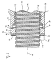
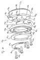
- FIG. 1 shows a ball screw drive, generally designated 10, a nut 12, a threaded spindle 14 with a spindle axis 16, an adapter 18 which can be fastened to an axial end of the nut 12 and includes a scraper assembly, generally indicated at 20, on the axially away from the nut 12 side of the adapter 18 on this is attachable.
- the first step is Fig. 2 referenced.
- the threaded spindle 14 has one in one Outer peripheral surface 22 of the spindle 14 has a screw thread 24 on, which is executed in a catchy manner in the example shown and by one external thread groove running helically around the spindle axis 16 26 is formed. It is understood that the screw thread 24 Threaded spindle 14 also has multiple threads, for example two threads can be.
- the nut 12, which surrounds the threaded spindle 14 in a ring also has at least one in its inner peripheral surface 28 helically extending nut groove 30 which, like the thread groove 26 in the outer peripheral surface 22 of the spindle 14 substantially has semicircular cross section.
- the nut groove 30 and the thread groove 26 together form a ball screw path that is not through one shown axial return channel in the nut 12 to a closed Ball circulation path is supplemented in which an endless row of balls 32 circulates.
- Adjacent to an axial end face 34 of the nut 12 is in the Inner circumferential surface 28 incorporated a profiled recess 36.
- This profiled recess 36 comprises an annular groove closer to the end face 34 38 and an annular groove 40 further away from the end face.
- the annular grooves 38, 40 are separated from one another by an annular web 42.
- the annular groove 38 is for End surface 34 bounded by an annular web 44.
- the annular groove 40 serves for receiving a retaining ring, not shown, which in the annular groove 40th can be snapped and a deflection piece, also not shown on the nut 12 ensures that the balls 32 in an axial end region of the Nut 12 between the ball screw path and the ball return channel deflects.
- the adapter 18 serving as the carrier of the wiper assembly 20 is on the Nut 12 can be clamped in any rotational angle position relative to mother 12. In his clamped on mother 12 The assembly state is the adapter 18 - in relation to the spindle axis 16 - both in the axial direction and in the circumferential direction on the nut 12 established.
- the adapter 18 is designed as a ring part, the Inner diameter slightly larger than the outer diameter of the spindle 14 is. Its outer diameter is approximately the same Outside diameter of the nut 12 in the face 34 subsequent axial end region. The adapter 18 closes in assembled condition on the outside essentially flush with the nut 12.
- annular flat surface 46 On the adapter 18 has an axially facing side of the nut 12 axially directed, annular flat surface 46, which is in contact with the surface the axial end face 34 of the nut 12 is determined.
- the flat surface 46 and the end face 34 form cooperating axial stops, which Set the axial position of the adapter 18 relative to the nut 12.
- annular support rib 48 Of the Flat surface 46 is an annular support rib 48 substantially in axial direction before, when mounting the adapter 18 on the mother 12 inserts into the recess 36 of the nut 12 and the adapter 18 on the Inner peripheral surface 28 of the nut 12, more precisely on the Inner circumferential surface of the ring web 44, centered.
- the adapter 18 has on its side facing axially away from the nut 12 an annular, flat mounting surface 50, which is used to attach the Wiper assembly 20 is used. Axially facing away from the nut 12 Side of the adapter 18 forth are several, four in the example shown, axial Fastening bores 52 drilled in the mounting surface 50.
- the Fastening holes 52 are designed as blind threaded holes and are with approximately equal angular distances from each other over the Mounting area 50 distributed. They are used to hold Fixing screws 54 shown in Fig. 1 and for fixing serve the wiper assembly 20 on the adapter 18.
- adapter 18 is by one of its inner circumference to its Outer circumference continuous, radially extending slot 56 on one Circumferential point separated.
- the slot 56 passes through in the axial direction the adapter 18 through. In the circumferential direction it is by two opposing slot boundary surfaces 58 and 60 limited.
- a recess 62 is incorporated, which extends through the axial direction
- Adapter 18 extends through and in the radial direction from the outer circumference of the adapter 18 up to one in the circumferential direction in the slot 56 projecting web 64 is sufficient.
- the Slit delimitation surface 58 is normal to the surface Slot boundary surface 58 extending bore 66 that approximately tangential to the circumferential direction from the outer circumference of the adapter 18 in this is incorporated.
- Threaded nut 68 To clamp the adapter 18 to the nut 12 is a Threaded nut 68 inserted into the recess 62 so that it on the Web 64 rests and on the recessed part of the slot boundary surface 58 is present.
- the threaded nut 68 has a threaded hole 70 which in the inserted state of the threaded nut 68 is aligned with the bore 66. What remains after inserting the nut 68 into the recess 62 Slot volume is then with an at least limited elastic Sealant 72 filled.
- the sealing compound 72 prevents the penetration of Contamination from outside of the adapter 18 into that of the adapter 18 enclosed interior and holds the nut 68 in the recess 62nd
- the nut 68 is preferably encapsulated with the sealing compound 72 so that it of the sealing compound 72 not only on the slot boundary wall 58 is held, but also in the radial direction and in the axial direction is secured against loss.
- the flat surface 46 becomes at least radially outside the mounting rib 48 also covered with a sealing compound 74, which in the assembled state of the adapter 18 a sealing layer between the flat surface 46 and the axial end face 34 of the nut 12 forms.
- This sealing covering seals the Connection point formed between the adapter 18 and the nut 12 against the ingress of dirt and against the escape of Lubricant and compensates for irregularities in the flat surface 46 or / and in the axial end face 34.
- the slot filling 72 and the Sealing coating 74 are advantageously in a common If necessary, the work process can be attached in one piece.
- the sealing or filling compound used can be a rubber compound, which is applied to the adapter 18 and vulcanized there. Is conceivable but also to apply a plastic compound in one spraying process.
- the adapter 18 thus prepared is axially on the end face 34 of the nut 12 scheduled.
- the mounting rib 48 engages - as already explained - in the recess 36 on the inner circumference of the nut 12.
- a clamping screw 76 (see FIG. 1) and screwed into the threaded nut 68.
- the Clamping screw 76 is screwed into the threaded nut 68 so far that with its first screwed end into the slot filling 72 digs in.
- the clamping screw 76 is screwed in further into the Threaded nut 68 held non-rotatably in the recess 62 presses the Fixing screw 76 finally so strong against that Slot boundary surface 60 that the adapter 18 expands. It is possible that the mounting screw 76 the material of the Slit filling 72 cuts through and in direct contact with the Slot boundary surface 60 arrives. It is also possible that the Fixing screw 76 only presses into the slot filling 72, without to hurt them.
- the slot width of slot 56 i.e. the slot volume increases.
- the sealing compound used for the slot filling 72 preferably has such elasticity that it increases the volume of the slot 56 can compensate and in the expansion of the adapter 18th the resulting additional slot volume can expand into it. This is advantageous so that not due to the additional slot volume Contaminants can penetrate or lubricants can escape.
- the threaded nut 68 is thereby always securely in the Recess 62 held.
- the adapter 18 may also be conceivable Adapter 18 not only axially onto the spindle end of the spindle 14 Slide the spindle 14, but in the radial direction onto the spindle 14 attach or subtract from this.
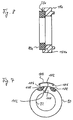
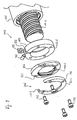
- the wiper assembly includes a sealing ring 80 engaging in the thread 24 of the spindle 14 the sealing ring 80, for example, to protect it from hot chips Cover plate 82 and a roughly the thread 24 of the spindle 14 pre-cleaning groove scraper 84.
- the components sealing ring 80, cover plate 82 and groove scraper 84 are by means of the fastening screws 54 on the Mounting surface 50 of the adapter 18 attachable.
- the sealing ring 80 has a set of through holes 86, the number of which the Blind holes 52 of the adapter 18 corresponds to and like that Blind holes 52 are arranged distributed in the circumferential direction, so that they can be brought into axial alignment with the blind bores 52.
- the Through holes 86 are designed without threads.
- That too Cover plate 82 has a set of through holes 88, which with the through holes 86 and the mounting holes 52 axially in Cover can be brought.
- the groove scraper 84 in Circumferential direction elongated receiving holes 90 which with the Through holes 88 of the cover plate 82 can be brought into axial overlap are. Since in the example shown in FIG. 1 the groove scratcher 84 is only one has a semicircular basic shape, it has only two receiving holes 90 while both the cover plate 82 and the sealing ring 80 each have four through holes 88 and 86, respectively.
- the sealing ring 80 has an inner circumferential surface 92, which with a thread profile 94 complementary to thread 24 of spindle 14 is executed.
- the sealing ring 80 On its side axially facing the adapter 18 the sealing ring 80 one for flat contact with the mounting surface 50 of the adapter 18 certain, axially directed contact surface 96 (see FIG. 3).
- the Sealing ring 80 On its axially facing away from the adapter 18, the Sealing ring 80 has an axially directed end face 98 into which one of the Contour of the cover plate 82 adapted receiving recess 100 is incorporated. The cover plate can be inserted into this recess 100 82 positively inserted, so that it is flush with the Recess 100 recessed part of the end face 98 of the sealing ring 80 inserts.
- the cover plate 82 is designed as a segment ring, but can have any other shape sufficient for the sealing ring 80 protects against damage.
- the sealing ring 80 is advantageously made of Plastic molded, for example injection molded, with the cover plate 82 is preferably a steel sheet, but if desired also from another metal, for example brass or aluminum, or also made of a suitable impact-resistant and heat-resistant plastic can.
- the sealing ring 80 is slotted.
- Fig. 7, which is a somewhat simplified top view of the sealing ring 80 shows.
- a separating slot 102 which runs obliquely to the radial direction, separates the sealing ring 80 at a circumferential location.
- the separation slot 102 is oriented essentially in the axial direction.
- By narrowing the slot 102 is a radial bias of the sealing ring 80, which it radially against the outer peripheral surface 22 of the spindle in the assembled state 14 preloaded. It has been shown that the radial bias Sealing or wiping effect of the sealing ring 80 is considerably improved can be.
- the slot 102 narrowed and so the sealing ring 80 are radially narrowed.
- FIGS. 1 and 7 104 For narrowing of the separation slot 102 is a biasing clip in FIGS. 1 and 7 104 shown, which is like a bow in the circumferential direction via the separation slot 102 passed and with bent temple ends 106 in relation to the Circumferential direction arranged on both sides of the separation slot 102 Insert receptacles 108 can be inserted.
- the mutual distance of the Insert receptacle 108 in the circumferential direction is selected so that at inserted biasing clip 104 the separation slot 102 narrowed so far or is even concluded that the desired bias of the Sealing ring 80 sets.
- the through holes 86 in the sealing ring 80 are biased a slight measure compared to the mounting holes 52 in the Adapter 18 offset transversely to the axial direction. For this reason, it recommends that the through holes 86 in the sealing ring 80 a little larger cross section than the threaded sections of the fastening screws 54 so that there is play between the fastening screws 54 and the through holes 86. It has been shown that usual Tolerances when drilling holes in plastic or metal parts are unavoidable, often enough to achieve the desired one slight play between the mounting screws 54 and To ensure through holes 86.
- the groove scraper 84 is preferably designed as a bent sheet metal part. He has a semicircular mounting portion 114 with the Receiving holes 90 and at least one axially bent Scraper section 116 at one end of the fastening section 114. For a single thread 24 of the spindle 14 is sufficient Scraper section 116 with one of the cross-sectional contour of the thread groove 26 adapted to the spindle 14, approximately crescent-shaped Scratching projection 118 is executed. In the example shown in FIG. 1 the groove scraper 84 has two scraper sections 116, which with their Scratching projections 118 for engaging a two-start thread Spindle are determined and diametrically opposite each other. The Forming the receiving holes 90 as elongated holes allows the Nutkratzen.84 to adjust circumferentially relative to the adapter 18, for an optimal engagement of the scratching projections 118 in the thread 24 of the Achieve spindle 14.
- the spindle drive shown in FIG. 1 is assembled as follows: First, the nut 12 is mounted on the spindle 14, as shown in FIG. 1 is already shown. Then the individual components of the Wiper assembly 20 by means of the fastening screws 54 on the Adapter 18 attached. The bias clip 104 must be at this time not yet be attached to the sealing ring 80, but not should be excluded. The pre-assembled unit from adapter 18, Sealing ring 80, cover plate 82 and groove scraper 84 is then attached mounted on the mother. For this purpose, the unit mentioned is on the spindle turned on what is necessary because the sealing ring 80 with its Threaded profile 94 engages in the thread 24 of the spindle 14.
- the unit is turned so far on the nut 12 until the adapter 18 with his Flat surface 46 or with the sealing coating 74 on the end face 34 of the nut 12 comes to the plant.
- the clamping screw 76 is then the adapter 18 and with it the wiper assembly 20 on the nut 12 fixed.
- An alternative procedure for the assembly of the spindle drive 10 consists of the adapter 18 on the nut mounted on the spindle 14 12 to fix and then install the spindle 14 in their spindle bearings, before the wiper assembly 20 is mounted on the adapter 18.
- the Wiper assembly 20 can namely even with the spindle 14 installed to be assembled. Due to its separation slot 102, the Sealing ring 80 are bent apart and radially onto the spindle 14 be plugged on. The intervention of the Create the thread profile 94 with the thread 24 of the spindle 14 easily.
- the cover plate 82 can also due to its partially annular design are easily plugged radially onto the spindle 14, which is also for the semi-ring shaped nut scraper 84 applies.
- the components of the Wiper assembly 20 are then secured by means of fastening screws 54 attached to the adapter 18, which in turn is fixed to the nut 12.
- the Disassembly of the spindle drive 10 can in turn in reverse order happen. Especially when only the sealing ring 80 is worn and should be replaced, the latter is recommended Procedure, since then neither the spindle 14 from its spindle bearings must be removed, the adapter 18 dismantled from the nut 12 must become. 3 shows the assembled state of the spindle drive 10.
- FIGS. 8 to 16 As far as it is the same or components acting in the same way - with the same reference numerals as in 1 to 7, but supplemented by a lowercase letter. To avoid repetitions, the following is essentially only on differences to the embodiment of FIGS. 1 to 7 discussed. Otherwise, reference is made to the preceding description of FIGS. 1 to 7 directed.
- Fig. 8 shows an alternative way of biasing the Sealing ring 80a. It is not as in the embodiment of FIG. 1 to 7 by a separate biasing element, namely the one there Preload clip 104, preloaded but in a circular shape in the Mounting surface 50a of the adapter 18a recessed bias receptacle 120a used, whose diameter is slightly smaller than the outer diameter of the Sealing ring 80a is in the relaxed state.
- a separate biasing element namely the one there Preload clip 104
- Fig. 9 shows an embodiment in which the wiper assembly 20b only the sealing ring 80b, but does not include a groove scratch. This is without further possible, provided that the spindle 14b is not heavily contaminated are to be feared that require a preliminary scraper.
- the sealing ring 80b is pretensioned in this case Embodiment in that the sealing ring 80b in one Sleeve approach 122b is used, which in the axial direction to the Cover plate 82b connects.
- the sleeve extension 122b can be made in one piece with the cover plate 82b, for example as a curved one Sheet metal part, but can also be made as a separately manufactured component on the Cover plate 82b may be attached, for example by gluing or Welding.
- the inner diameter of the sleeve shoulder 122b is again dimensioned slightly smaller than the outer diameter of the sealing ring 80b in the relaxed state, so that the separating slot 102b of the Sealing ring 80b narrowed and the sealing ring 80b radially biased when the cover plate 82b with the sleeve lug 122b on the Sealing ring 80b are placed.
- One of the cover plate 82b separate biasing element, such as the biasing clip 104 in FIGS. 1 and 7, can be omitted in the embodiment of FIG. 9.
- the Assembly and disassembly of the spindle drive 10b shown in FIG. 9 take place analogously to that for the exemplary embodiment of FIGS. 1 to 7 described procedure.
- FIG. 10 shows a spindle drive 10c, in which the stripper assembly 20c does not include a sealing ring, but only the groove scraper 84c.
- This is attached to the adapter 18c by two fastening screws, as from 1 is readily apparent. That leaves two Mounting holes of the adapter 18c unoccupied. Since the groove scraper 84c only has the effect of a pre-scraper and only coarser impurities removed from the spindle thread 24c is sufficient to achieve Sealing the nut 12c against the spindle 14c one of the Wiper assembly 20c separate sealing ring 124c in the ring groove 38c of the nut 12c used. The sealing ring is in this ring groove 38c 124c axially fixed by the ring webs 42c and 44c.
- the sealing ring 124c is preferably made of an elastomeric material and has one radially inwardly projecting annular sealing lip 126c with a Lip edge 128c on the outer peripheral surface 22c of the spindle 14c fits tightly.
- the sealing lip 126c is flexible in the axial direction deflectable so that they optimally adhere to the outer peripheral surface 22c Spindle 14c hugs.
- the sealing ring 124c is preferably radial Preload installed to increase the sealing effect. It should be noted that the assembly of the adapter 18c on the nut 12c through the sealing ring 124c is not hindered because the mounting rib 48c of the adapter 18c does not extend axially beyond the ring web 44c of the nut 12c.
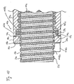
- FIGS. 11 to 14 there is not the clamping screw 76e in one screwed into the slot 56e inserted separate nut, but in a screw thread 168e formed in the tangential bore 66e.
- the slot boundary surface 60e is a countersink recess 170e educated.
- the clamping screw 76e into the screw thread 168e the tangential bore 66e is screwed in to the adapter 18e on the To clamp the nut, the bridging slot 56e is supported leading end of the clamping screw 76e in the countersink recess 170e, what with further screwing the clamping screw 76e to expand the Slot 56e leads.
- the blind holes 52e in the adapter 18e are designed as stepped bores and one in each Have mounting surface 50e opening step-shaped extension 172e.
- the diameter of the Through holes 86e in the sealing ring 80e corresponds to that Outer diameter of the spacer sleeves 174e.
- the Sealing ring 80e In the relaxed state of the Sealing ring 80e is also the circumferential distance between the two on both sides Separation slot 102e lying through holes 86e slightly larger than that Circumferential distance between the two opposite step extensions 172e in the adapter 18e.
- To assemble the wiper assembly 20e on the Adapter 18e can thus first of all seal ring 80e into the adapter 18e inserted spacer sleeves 174e, for this purpose the Sealing ring 80e somewhat in the area of its separating slot 102e is squeezed. This results in a radial Self-biasing of the sealing ring 80e, which it without falling off the adapter 18e holds when released by the assembler becomes.
- the length of the spacer sleeves 174e is preferably such that it protrude somewhat into the recess 100e of the sealing ring 80e into which the cover plate 82e is used.
- the cover plate 82e is then at the assembly of the wiper assembly 20e against the spacer sleeves 174e pressed, which in turn is in the step extensions 172e of the adapter Support 18e.
- the fastening screws 54e thus takes place no axial crushing of the preferably made of plastic Sealing ring 80e. Since the adapter 18e, the spacer sleeves 174e and that Cover plate 82e preferably made of metal which is not subject to crushing exist, the mounting screws 54e can still be so tight be tightened so that they are even in strong operational conditions Do not solve vibrations.
- determining a suitable Tightening torque for the fastening screws 54e not the Temperature dependence of the material hardness of the sealing ring 80e be taken into account.
Description
Die Erfindung betrifft einen Spindeltrieb gemäß dem Oberbegriff des
Anspruch 1.The invention relates to a spindle drive according to the preamble of
Ein solcher Spindeltrieb ist aus der US-A-2818745 bekannt. Bei dieser bekannten Ausführung ist der Adapter von einer einfachen Zylinderhülse gebildet. Der zylinderhülsenartige Adapter umgibt mit 'einem seiner Längsenden einen Endbereich der Mutter und ist an diesem mittels in radialer Richtung durch den zylinderhülsenartigen Adapter hindurch eingedrehten Madenschrauben festgelegt. Über den Umfang ist eine Mehrzahl von Madenschrauben vorgesehen, um eine Zentrierung des Adapters bezüglich der Mutter erreichen zu können.Such a spindle drive is known from US-A-2818745. At this known version is the adapter of a simple cylinder sleeve educated. The cylindrical sleeve-like adapter surrounds' one of its Longitudinal ends of an end portion of the nut and is on this means in radial Directed through the cylindrical sleeve-like adapter Set screws set. There are a number of Set screws provided to center the adapter with respect to the To be able to reach mother.
Nachteilig an dieser Lösung ist, dass der die Spindel umgehende Adapter nur mit Mühe in radialer Richtung durch die mehreren in Umfangsrichtung vorhandenen in radialer Richtung eingedrehten Madenschrauben fixiert werden kann. Zum einen liegt eine Krafteinleitung einer Fixierungskraft nur an den Auflagepunkten der Madenschraube an der Außenseite der Mutter vor. Zum anderen führt ein Eindrehen der Madenschraube nach Anlage an der Außenfläche.der Mutter sehr leicht zu einer ungleichmäßigen Verformung an dem Durchgangsloch für die Madenschraube. Dies erschwert eine sichere und positionsgenaue Anbringung des Adapters. Darüber hinaus ist die Anbringung des Adapters an der Mutter durch die zahlreichen Schraubvorgänge an den Madenschrauben umständlich und zeitaufwendig.The disadvantage of this solution is that the adapter bypassing the spindle only with difficulty in the radial direction through the plurality in the circumferential direction existing grub screws screwed in in the radial direction can be. On the one hand, force is only applied to a fixing force the support points of the grub screw on the outside of the nut. On the other hand, screwing in the grub screw after contacting the Outer surface. Of the nut very easily to an uneven deformation the through hole for the grub screw. This makes safe and difficult precise positioning of the adapter. In addition, the attachment of the adapter on the nut through the numerous screwing operations on the Set screws cumbersome and time consuming.
Ein weiterer Spindeltrieb ist aus der DE 28 22 560 A1 bekannt. Bei der bekannten Lösung umfaßt die Abstreiferbaugruppe einen am Innenumfang einer Hülse angebrachten Dichtungsring, der am Gewinderücken eines Außengewindes der Spindel dichtend anliegt. Der Dichtungsring ist mit der Hülse unlösbar vernietet. Die aus dem Dichtungsring und der Hülse bestehende Abstreiferbaugruppe ist bei auf der Spindel montierter Mutter an dieser befestigbar. Hierzu ist an die Mutter ein axial abstehender Rohransatz angeschweißt. Auf diesen Rohransatz wird die den Dichtungsring tragende Hülse der Abstreiferbaugruppe aufgeschoben. Sodann wird die Abstreiferbaugruppe in axialer Richtung gegenüber dem Rohransatz manuell ausgerichtet, bis der Dichtungsring auf dem Gewinderücken des Außengewindes der Spindel optimal positioniert ist. Nach erfolgter Ausrichtung wird die Abstreiferbaugruppe durch Stifte und eine Klemmschelle axial und in Umfangsrichtung an dem Rohransatz fixiert.Another spindle drive is known from DE 28 22 560 A1. In the Known solution includes the wiper assembly on the inner circumference a sleeve attached sealing ring on the back of a thread External thread of the spindle is sealing. The sealing ring is with the Riveted riveted sleeve. The one from the sealing ring and the sleeve existing wiper assembly is with the nut mounted on the spindle attachable to this. For this purpose, an axially protruding from the nut Welded pipe socket. On this pipe approach the The sleeve of the wiper assembly bearing the sealing ring is pushed on. Then the wiper assembly in the axial direction against the Manually align the pipe extension until the sealing ring on the Thread back of the external thread of the spindle is optimally positioned. After alignment, the wiper assembly is replaced by pins and a clamp is fixed axially and circumferentially on the pipe socket.
Die bekannte Lösung erfordert Anpassungsarbeiten an der Mutter, um die Abstreiferbaugruppe montieren zu können. Es muß die Mutter einem Schweißvorgang unterworfen werden, um den Rohransatz an ihr zu befestigen. Soll eine als Serienbauteil erhältliche, herkömmliche Mutter verwendet werden, so ist es häufig überhaupt nicht möglich, von außen her einen Rohransatz an diese anzuschweißen. Häufig läßt das Material der Mutter oder/und mit ihr verbundener Komponenten das Anschweißen eines Rohransatzes gar nicht zu, etwa aufgrund hoher Wärmeempfindlichkeit, starker Verformungsgefahr oder schlechter Schweißeigenschaften. Dies gilt speziell für Präzisionsspindeltriebe, wie sie beispielsweise in Werkzeugmaschinen oder Meßeinrichtungen eingesetzt werden. Das Schweißen stellt zudem einen vergleichsweise aufwendigen und schwierigen Vorgang dar, da der Rohransatz in radialer Richtung exakt positioniert werden muß, um über den gesamten Umfang gleichmäßige Anlageverhältnisse des Dichtungsrings am Gewinderücken des Spindelgewindes sicherzustellen. Auch ist an herkömmlichen Muttern häufig aus konstruktiven oder Platzgründen keine geeignete Stelle zum Anschweißen eines Rohransatzes zu finden. Schließlich ist der Rohransatz nach dem Anschweißen nicht mehr von der Mutter abnehmbar, so daß die Mutter auf einen bestimmten Einsatzzweck festgelegt ist und nicht mehr für andere Einsatzzwecke herangezogen werden kann, bei denen eine axial von außen angebrachte Abstreiferbaugruppe unter Umständen gar nicht mehr benötigt wird. Der angeschweißte Rohransatz wäre dann nur störend und würde unnötigen Bauraum beanspruchen.The known solution requires adaptation work on the mother to the To be able to mount the wiper assembly. It must be the mother Welding process to be subjected to the pipe attachment to it Fasten. Should be a conventional nut available as a series component are used, so it is often not possible at all from the outside to weld a pipe neck to this. Often the material of the Mother or / and components connected to it, welding one Not at all due to high heat sensitivity, severe risk of deformation or poor welding properties. this applies especially for precision spindle drives, such as those in Machine tools or measuring devices are used. The Welding also represents a comparatively complex and difficult process, since the pipe attachment in the radial direction exactly must be positioned to be uniform over the entire circumference System conditions of the sealing ring on the back of the thread Ensure the thread of the spindle. Also common on conventional nuts for constructional or space reasons no suitable position for Find welding a pipe neck. Finally, the pipe neck after welding can no longer be removed from the mother, so that the Mother is committed to a specific purpose and no longer for other uses can be used, in which an axial of the scraper assembly attached to the outside may no longer be at all is needed. The welded pipe socket would then only be annoying and would take up unnecessary space.
Aus der deutschen Patentschrift DE 20 01 558 ist ein weiterer Spindeltrieb
mit einer Spindel und einer in Schraubeingriff mit der Spindel stehenden
Mutter bekannt, bei dem im montierten Zustand der Mutter ein
Dichtungsring von axial außen her an dieser angebracht werden kann. Der
Dichtungsring greift in eine Gewindenut in der Außenumfangsfläche der
Spindel ein und wird von einem Spindelende her auf die Spindel aufgedreht.
In einer axialen Stirnfläche der Mutter sind über den Umfang verteilt
mehrere axial gerichtete Zapfenaufnahmelöcher vorgesehen. Ähnliche
Zapfenaufnahmelöcher sind auch in dem Dichtungsring vorgesehen. Wenn
der Dichtungsring bei seiner Montage in die gewünschte axiale Position
relativ zur Mutter gedreht ist, werden die Zapfenaufnahmelöcher in dem
Dichtungsring und der Mutter in Deckung gebracht und dann mit Zapfen
besetzt, die den Dichtungsring verdrehsicher an der Mutter halten. Durch ein
sich an der Mutter abstützendes Vorspannorgan wird der Dichtungsring
axial von der Mutter weg gegen die Gewindegänge des Spindelgewindes
vorgespannt.Another spindle drive is from German
Auch bei der Lösung nach der DE 20 01 558 kann nicht ohne weiteres auf eine herkömmliche, handelsübliche Mutter zurückgegriffen werden, um den Dichtungsring anbringen zu können. Vielmehr muß die Mutter erst gezielt bearbeitet werden, um die Voraussetzungen für die Montage des Dichtungsrings zu schaffen. Es müssen nämlich die Zapfenaufnahmelöcher gebohrt werden, was einen zusätzlichen Arbeitsaufwand mit sich bringt. Zudem ist die Montage des Dichtungsrings außerordentlich mühsam, da der Dichtungsring gegen die Wirkung des Vorspannorgans relativ zur Mutter festgehalten werden muß, um die einzelnen Zapfen in die in Deckung gebrachten Zapfenaufnahmelöcher einsetzen zu können.Even with the solution according to DE 20 01 558 it is not easy to a conventional, commercially available mother can be used To be able to attach the sealing ring. Rather, the mother must first be targeted are processed to meet the requirements for the assembly of the To create a sealing ring. Namely, there must be the pin receiving holes be drilled, which entails additional work. In addition, the assembly of the sealing ring is extremely tedious because of Sealing ring against the action of the pretensioning member relative to the nut must be held to cover the individual pegs in the to be able to use the provided pin receiving holes.
Der Erfindung liegt demnach die Aufgabe zugrunde, einen gattungsgemäßen Spindeltrieb anzugeben, welcher einfach und schnell an der Mutter montierbar und in sicherer Weise an dieser auch in radialer Richtung fixierbar ist.The invention is therefore based on the object, a generic Specify spindle drive, which can be easily and quickly mounted on the nut and can also be securely fixed to it in the radial direction.
Diese Aufgabe wird erfindungsgemäß gelöst durch einen Spindeltrieb mit den
Merkmalen des Anspruchs 1 und durch einen Bansatz zur
Nachrüstung eines Spindeltriebs gemäß Anspruch 56.
Eine Fixierung des Adapters an der Mutter in radialer Richtung wird erfindungsgemäß
dadurch erreicht, daß der Adapter mindestens einen im wesentlichen in
Achsrichtung der Spindel zur Mutter hin weisenden Halterungsansatz
aufweist. Der Halterungsansatz dient zur Zentrierung des Adapters an der
Mutter. Gewünschtenfalls kann ein solcher Halterungsansatz auch zur
Fixierung des Adapters in Umfangsrichtung vorgesehen sein. Der
Halterungsansatz ist als Ringrippe oder Ringrippensegment ausgebildet,
Zweckmäßigerweise ist die Mutter mit wenigstens einer
Halterungsaufnahme zur Aufnahme des Halterungsansatzes ausgeführt.
Diese Halterungsaufnahme ist von einer Innenumfangsfläche der Mutter
radial begrenzt. Bei handelsüblichen Muttern ist häufig im Bereich ihrer
axialen Enden ein ringförmiger Zwischenraum zwischen der
Außenumfangsfläche der Spindel und der Innenumfangsfläche der Mutter
vorhanden. In diesen radialen Zwischenraum kann der Adapter mit seinem
Halterungsansatz eingeführt werden, so daß der Halterungsansatz mit der
Innenumfangsfläche der Mutter in Halterungseingriff steht.This object is achieved according to the invention by a spindle drive with the features of
The nut is expediently designed with at least one mounting receptacle for receiving the mounting attachment. This mount is radially delimited by an inner peripheral surface of the nut. In the case of commercially available nuts, an annular space is often present in the area of their axial ends between the outer peripheral surface of the spindle and the inner peripheral surface of the nut. In this radial space, the adapter with its mounting lug can be inserted so that the mounting lug is in mounting engagement with the inner peripheral surface of the nut.
Der Adapter kann zweckmäßigerweise als Ringteil ausgebildet sein. Eine einfache und schnelle Montage des Adapters an der Mutter ist dadurch möglich, daß der Adapter in Umfangsrichtung durch eine Schlitzung aufgetrennt ist, deren Schlitzweite durch Schlitzweitenbeeinflussungsmittel beeinflußbar ist, und daß der Adapter durch Beeinflussung der Schlitzweite der Schlitzung an der Mutter festklemmbar ist. Modifikationen an der Mutter in Form einer nachträglichen Bearbeitung derselben sind bei dieser Art der Montage an sich nicht notwendig, da durch geeignete Gestaltung des Adapters dieser an im wesentlichen jeder beliebigen vorhandenen Fläche der Mutter festgeklemmt werden kann. Die Schlitzweitenbeeinflussungsmittel können als Schlitzeinengungsmittel ausgebildet sein, wobei der Adapter dann gegen eine Außenumfangsfläche der Mutter festklemmbar sein kann. Ebenso ist möglich, daß die Schlitzweitenbeeinflussungsmittel als Schlitzaufweitungsmittel ausgebildet sind und der Adapter gegen eine Innenumfangsfläche der Mutter festklemmbar ist. Eine zum Festklemmen des Adapters geeignete Außen- oder Innenumfangsfläche ist bei herkömmlichen Muttern im Regelfall vorhanden.The adapter can expediently be designed as a ring part. A This makes the adapter easy and quick to mount on the nut possible that the adapter circumferentially through a slit is separated, the slot width by slot width influencing means can be influenced, and that the adapter by influencing the slot width the slit can be clamped to the nut. Modifications to the mother in the form of a subsequent processing of these are the Assembly itself is not necessary, because by suitable design of the Adapters this on essentially any existing surface Nut can be clamped. The slot width influencer can be designed as slot narrowing means, the adapter can then be clamped against an outer peripheral surface of the nut. It is also possible that the slot width influencing means as Slot expansion means are formed and the adapter against one Inner circumferential surface of the nut can be clamped. One for clamping suitable outer or inner circumferential surface is at conventional nuts are usually available.
Der von Abstreifaufgaben freie Adapter bildet eine Schnittstelle zwischen der Mutter und der Abstreiferbaugruppe. Er ist ein von der Mutter und von der Abstreiferbaugruppe körperlich gesondert ausgebildetes Bauteil - oder eine Baueinheit. Dieses Bauteil oder diese Baueinheit kann einerseits optimal an die an der Mutter, insbesondere an einer herkömmlichen Mutter, vorhandenen Befestigungsmöglichkeit angepaßt werden. Dies bedeutet, daß der Adapter so konstruiert werden kann, daß er an der Mutter befestigbar ist, ohne die Mutter hierzu speziell bearbeiten zu müssen, beispielsweise einen geschweißten Rohransatz vorsehen zu müssen oder Bohrungen anbringen zu müssen. Die Mutter kann dann auch für solche Einsatzzwecke weiterverwendet werden, bei denen die Abstreiferbaugruppe mit dem Adapter nicht erwünscht oder nicht notwendig ist. Andererseits kann der Adapter auch optimal an die an der Abstreiferbaugruppe vorhandenen Befestigungsmöglichkeiten angepaßt werden. Es ist nämlich zu bedenken, daß bei der Konstruktion der Abstreiferbaugruppe regelmäßig zunächst ihre Abstreiffunktion im Vordergrund steht, weswegen bei der Befestigung der Abstreiferbaugruppe stets Rücksicht darauf genommen werden muß, daß die Abstreiffunktion optimal gewährleistet ist. Der Adapter löst den hier evidenten Zielkonflikt zwischen einer einfachen, dennoch betriebssicheren Befestigung der Abstreiferbaugruppe bei gleichzeitig gewährleisteter, optimaler Abstreiffunktion und der gewünschten Unversehrtheit der Mutter, so daß auf eine handelsübliche Mutter zurückgegriffen werden kann, die keiner Nachbearbeitung bedarf.The adapter, which is free of stripping tasks, forms an interface between the mother and the wiper assembly. He is one of the mother and one the wiper assembly physically separate component - or a unit. On the one hand, this component or unit can be optimal to those on the mother, especially on a conventional mother, existing mounting option can be adjusted. This means that the adapter can be designed so that it can be attached to the nut without having to edit the mother specifically, for example to have to provide a welded pipe socket or holes to have to attach. The mother can then also be used for such purposes continue to be used in which the wiper assembly with the Adapter is not desired or not necessary. On the other hand, the Adapters also optimally match those on the wiper assembly Fastening options can be adjusted. It should be borne in mind that in the construction of the wiper assembly regularly first their Scraper function is in the foreground, which is why when attaching the Wiper assembly must always take into account that the wiping function is optimally guaranteed. The adapter solves this evident conflict of goals between a simple, yet reliable Attachment of the scraper assembly with guaranteed, optimal stripping function and the desired integrity of the mother, so that a commercially available mother can be used no post-processing is required.
Montagetechnisch günstig ist es, wenn zumindest die Abstreiferkomponente in einem Montagezustand der Mutter, in dem diese auf der Spindel montiert ist, an der Mutter montierbar und von dieser demontierbar ist. Die Spindel muß dann nicht aus ihren Spindellagern ausgebaut werden, um die Abstreiferkomponente unter Zwischenschaltung des Adapters an der Mutter befestigen zu können. Dabei empfiehlt es sich, daß auch der Adapter in dem Montagezustand der Mutter an dieser montierbar und von dieser demontierbar ist.In terms of assembly technology, it is favorable if at least the wiper component in an assembled state of the nut, in which it is mounted on the spindle is mountable on and removable from the nut. The spindle then does not have to be removed from their spindle bearings to the Wiper component with the adapter on the nut to be able to attach. It is recommended that the adapter in the Mounting state of the mother mountable on this and from this is removable.
Die Montage des Spindeltriebs wird weiter vereinfacht, wenn wenigstens ein die Abstreiferkomponente umfassender Teil der Abstreiferbaugruppe und der Adapter zu einer Baueinheit vormontierbar sind und als Baueinheit an der Mutter anbringbar sind. Hierbei ist es wiederum günstig, wenn die vormontierte, die Abstreiferkomponente und den Adapter umfassende Baueinheit in einem Montagezustand der Mutter, in dem diese auf der Spindel montiert ist, an dieser montierbar und von dieser demontierbar ist.The assembly of the spindle drive is further simplified if at least a part of the wiper assembly comprising the wiper component and the adapter can be pre-assembled into a structural unit and as a structural unit on the Mother can be attached. It is again favorable if the pre-assembled, comprising the wiper component and the adapter Unit in an assembled state of the mother, in which this on the Spindle is mounted, can be mounted on and removed from this.
Eine mühsame axiale Ausrichtung des Adapters relativ zur Mutter wird vermieden, wenn an dem Adapter und an der Mutter zusammenwirkende erste Axialanschlagmittel vorgesehen sind, welche die Axialposition des Adapters relativ zur Mutter festlegen. Bevorzugt ist auch die Abstreiferkomponente axial fest mit dem Adapter verbindbar. ihre Montage an dem Adapter wird dann dadurch erleichtert, daß an der Abstreiferbaugruppe und an dem Adapter zusammenwirkende zweite Axialanschlagmittel vorgesehen sind, welche die Axialposition der Abstreiferkomponente relativ zum Adapter festlegen.A tedious axial alignment of the adapter relative to the nut becomes avoided when interacting on the adapter and on the nut first axial stop means are provided, which the axial position of the Set the adapter relative to the mother. The is also preferred Wiper component can be connected axially fixed to the adapter. their assembly on the adapter is then facilitated by the fact that Wiper assembly and second cooperating on the adapter Axial stop means are provided, which the axial position of the Specify the wiper component relative to the adapter.
Es empfiehlt sich, daß zur Befestigung des Adapters an der Mutter und zur Befestigung der Abstreiferbaugruppe an dem Adapter jeweils gesonderte Befestigungsorgane vorgesehen sind. Für unterschiedliche Muttern oder/und unterschiedliche Abstreiferbaugruppen können dann die jeweils geeigneten Befestigungsorgane gewählt werden.It is recommended that to attach the adapter to the nut and Separate attachment of the wiper assembly to the adapter Fasteners are provided. For different nuts or / and different scraper assemblies can then be the most suitable Fasteners can be selected.
Wenn die Abstreiferbaugruppe eine Abstreiferkomponente umfaßt, die in eine Gewindenut der Außenoberfläche der Spindel eingreift, kann die Abstreiferbaugruppe zu ihrer Montage üblicherweise nicht axial auf die Spindel aufgeschoben werden, sondern muß vielmehr auf die Spindel aufgedreht werden. Eine einfache Montage des Spindeltriebs ohne Justieraufwand wird dann dadurch gewährleistet, daß zur Befestigung des Adapters an der Mutter Befestigungsmittel vorgesehen sind, welche eine von der Drehstellung des Adapters relativ zur Mutter unabhängige Befestigung des Adapters erlauben.If the wiper assembly comprises a wiper component which is in a threaded groove engages the outer surface of the spindle, the Scraper assembly for their assembly usually not axially on the Spindle be pushed on, but rather must be on the spindle be turned up. A simple assembly of the spindle drive without Adjustment effort is then ensured in that the attachment of the Adapters are provided on the mother fasteners, which a independent of the rotational position of the adapter relative to the nut Allow attachment of the adapter.
Es ist denkbar, daß unterschiedlichen Abstreiferbaugruppen jeweils ein eigener Adaptertyp zugeordnet ist. Ein wesentlicher Gedanke der Erfindung ist jedoch, einen Universaladapter bereitzustellen, der zur wahlweisen Befestigung unterschiedlicher Abstreiferbaugruppen ausgebildet ist. Die Unterschiedlichkeit der Abstreiferbaugruppen kann in einer unterschiedlichen Zahl oder/und Gestaltung ihrer Abstreiferkomponenten bestehen. Für unterschiedliche Abstreiferbaugruppen kann der Adapter dabei unterschiedliche Anbringungsstellen aufweisen. Bevorzugt ist jedoch vorgesehen, daß der Adapter zur Anbringung einer Abstreiferbaugruppe Anbringungsstellen aufweist, die für verschiedene Abstreiferbaugruppen gleich sind.It is conceivable that different wiper assemblies each own adapter type is assigned. An essential idea of the invention is, however, to provide a universal adapter that is optional Attachment of different wiper assemblies is formed. The Diversity of the wiper assemblies can be different Number and / or design of their wiper components exist. For the adapter can use different wiper assemblies have different locations. However, is preferred provided that the adapter for attaching a wiper assembly Has attachment points for different wiper assemblies are the same.
Die Abstreiferbaugruppe kann mindestens zwei körperlich gesondert ausgebildete Abstreiferkomponenten umfassen. Zumindest ein Teil der Abstreiferkomponenten kann dabei axial hintereinander in Abstreifeingriff mit der Außenumfangsfläche der Spindel stehen. Die Abstreiferkomponenten können unterschiedliche Funktionen übernehmen, so daß sich eine hochwirksame Abstreiferbaugruppe realisieren läßt, die die Mutter perfekt nach außen hin abdichtet. So ist es denkbar, daß sich zwei axial hintereinander in Abstreifeingriff mit der Außenumfangsfläche der Spindel stehende Abstreiferkomponenten hinsichtlich ihrer Abstreifwirkung unterscheiden. Zweckmäßig ist es, dann eine von einem axialen Zentralbereich der Mutter weiter entfernt in Abstreifeingriff mit der Außenumfangsfläche der Spindel stehende Abstreiferkomponente einen Vorabstreifer mit gröberer Abstreifwirkung bildet und eine näher an dem axialen Zentralbereich der Mutter in Abstreifeingriff mit der' Außenumfangsfläche der Spindel stehende Abstreiferkomponente einen Hauptabstreifer mit feinerer Abstreifwirkung bildet.The wiper assembly can physically separate at least two trained wiper components include. At least part of the Wiper components can be wiped axially one behind the other stand with the outer peripheral surface of the spindle. The wiper components can take on different functions, so that a highly effective scraper assembly can be realized, the mother seals perfectly to the outside. So it is conceivable that two axially successively in wiping engagement with the outer peripheral surface of the spindle standing wiper components with regard to their wiping effect differ. It is expedient then one of an axial Central area of the mother further away in scraping engagement with the Scraper component standing outer circumferential surface of the spindle Pre-scraper with coarser wiping action forms and one closer to that axial central area of the nut in wiping engagement with the ' Scraper component standing outer circumferential surface of the spindle Main wiper forms with a finer wiping effect.
Zur Verbesserung der Abdichtung der Mutter kann vorgesehen sein, daß in dem axialen Endbereich der Mutter mindestens ein zusätzliches, von der Abstreiferbaugruppe gesondertes Abstreiferelement an der Mutter befestigt oder befestigbar ist. Zweckmäßigerweise wird dieses zusätzliche Abstreiferelement näher als die Abstreiferbaugruppe zu einem axialen Zentralbereich der Mutter hin an dieser befestigt oder befestigbar sein. Zur Aufnahme des zusätzlichen Abstreiferelements kann an der Mutter eine Abstreiferelementenaufnahmenut ausgebildet sein. Bei handelsüblichen Muttern ist eine solche Abstreiferelementenaufnahmenut häufig in Form einer Ringnut ausgebildet, in die als zusätzliches Abstreiferelement ein Dichtungsring eingesetzt werden kann. Damit steht dem Anwender des Spindeltriebs die Möglichkeit offen, in Ergänzung zur Abstreiferbaugruppe einen zusätzlichen Dichtungsring an der Mutter zu montieren oder diesen wegzulassen.To improve the sealing of the mother can be provided that in the axial end region of the nut at least one additional, from the Scraper assembly separate scraper element attached to the nut or is attachable. This is expediently additional Wiper element closer to an axial than the wiper assembly Central area of the mother attached to it or be attachable. to The additional wiper element can be added to the nut Wiper element receiving groove be formed. With commercially available Such a wiper element receiving groove is often in the form of nuts formed an annular groove into which an additional wiper element Sealing ring can be used. The user of the Spindle drive the possibility open, in addition to the wiper assembly to mount an additional sealing ring on the nut or this omit.
Bei einer bevorzugten Ausführungsform ist vorgesehen, daß der Adapter eine axial von der Mutter weg gerichtete Montagefläche zur Befestigung der Abstreiferbaugruppe aufweist. In der Montagefläche können dann mehrere - bezogen auf die Spindelachse - in Umfangsrichtung verteilt angeordnete, axiale Befestigungsbohrungen zur Aufnahme von Befestigungsbolzen ausgebildet sein, die der Befestigung der Abstreiferbaugruppe an der Montagefläche des Adapters dienen. Wenigstens ein Teil der Befestigungsbohrungen kann als Sacklochbohrungen ausgebildet sein. Alternativ oder zusätzlich kann wenigstens ein Teil der Befestigungsbohrungen axial durch den Adapter hindurchgehen, was es erlaubt, von axial beiden Seiten des Adapters her Befestigungsbolzen in diese Befestigungsbohrungen einzusetzen. In a preferred embodiment it is provided that the adapter an axially directed away from the mother mounting surface for fastening the Wiper assembly. Then several - in relation to the spindle axis - distributed in the circumferential direction, axial mounting holes for mounting mounting bolts be formed, the attachment of the wiper assembly to the Mounting surface of the adapter. At least part of the Fastening holes can be designed as blind holes. Alternatively or additionally, at least part of the Mounting holes go axially through the adapter, which it is allowed fastening bolts in axially from both sides of the adapter use these mounting holes.
Bei einer bevorzugten Lösung, die sich durch eine geringe Bauteilezahl und zuverlässige und einfache Handhabung auszeichnet, umfassen die Schlitzweitenbeeinflussungsmittel eine Schlitzweitenbeeinflussungsschraube, die in eine Bohrung in dem Adapter einsetzbar ist, die in eine Schlitzbegrenzungsfläche der Schlitzung mündet. Da es unter Unterständen schwierig sein kann, in die Bohrung ein Gewinde einzuschneiden, beispielsweise weil die Wandstärke um die Bohrung herum zu gering ist, ist bevorzugt vorgesehen, daß in der Schlitzung eine körperlich gesondert ausgebildete Gewindemutter gehalten ist, mit der die Schlitzweitenbeeinflussungsschraube in Gewindeeingriff bringbar ist. Zur richtigen Positionierung der Gewindemutter empfiehlt es sich, daß diese in einer Ausnehmung in einer Schlitzbegrenzungsfläche der Schlitzung angeordnet ist. In a preferred solution, which is characterized by a small number of components and reliable and easy handling, include Slot width influencing means a slot width influencing screw, which can be inserted into a hole in the adapter, which in a slot boundary surface of the slot opens. Since it's under Shelters can be difficult to thread into the hole cut, for example because the wall thickness around the hole is too small, it is preferably provided that a physical in the slit separately trained threaded nut is held with the slot width influencing screw can be brought into thread engagement. The right one Positioning the threaded nut, it is recommended that this in a Recess arranged in a slot boundary surface of the slot is.
Aus Festigkeitsgründen und zur leichten Bearbeitbarkeit wird der Adapter bevorzugt aus Metall gefertigt, wobei ein besonders leichtes Gewicht des Adapters durch die Verwendung von Aluminium gewährleistet ist. Es versteht sich jedoch, daß der Adapter auch aus Kunststoff gefertigt sein kann, beispielsweise als Spritzgußteil.The adapter is used for reasons of strength and for easy workability preferably made of metal, with a particularly light weight of the Adapters is guaranteed by the use of aluminum. It however, it goes without saying that the adapter can also be made of plastic can, for example as an injection molded part.
Eventuelle vorhandene Undichtigkeiten zwischen dem Adapter und der Mutter können dadurch beseitigt werden, daß eine zur Anlage an der Mutter bestimmte Anlagefläche des Adapters wenigstens zum Teil mit einem Materialüberzug versehen ist. Der Materialüberzug kann aus aufvulkanisiertem Gummi oder aufgespritztem Kunststoff bestehen und besitzt bevorzugt eine gewisse Elastizität, so daß er Undichtigkeitsstellen zwischen dem Adapter und der Mutter vollständig ausfüllen kann. Sofern der Adapter mit einer Schlitzung ausgeführt ist, empfiehlt es sich, daß auch diese Schlitzung zumindest teilweise mit insbesondere verformungsfähigen Dichtmaterial ausgefüllt ist, um das Eindringen von Verunreinigungen durch die Schlitzung zu verhindern. Wenn bei einer derartigen geschlitzten Ausführung des Adapters die Schlitzweite zum Festklemmen des Adapters verändert wird, ist es günstig, wenn das Dichtmaterial der Schlitzweitenveränderung folgen kann, also im Falle einer Schlitzeinengung elastisch kompressibel ist und sich im Falle einer Schlitzaufweitung in das zusätzlich entstandene Schlitzvolumen hinein ausdehnen kann.Any existing leaks between the adapter and the Mothers can be eliminated by having one against the mother certain contact surface of the adapter at least partially with one Material cover is provided. The material covering can be made vulcanized rubber or sprayed plastic and preferably has a certain elasticity so that it leaks between the adapter and the nut. Provided the adapter is designed with a slot, it is recommended that too this slitting at least partially with particularly deformable Sealing material is filled in to prevent the ingress of contaminants to prevent the slitting. If in such a slotted Version of the adapter the slot width for clamping the adapter is changed, it is favorable if the sealing material of the Slot width change can follow, so in the case of a slot narrowing is elastically compressible and in the event of a slot expansion into the can also expand the resulting slot volume.
Nach einer Weiterbildung der Erfindung ist vorgesehen, daß die Abstreiferbaugruppe als eine Abstreiferkomponente einen Abstreiferring umfaßt, der im wesentlichen über seinen gesamten Innenumfang in Dichteingriff mit der Außenumfangsfläche der Spindel steht. Eine gute Dichtwirkung läßt sich erreichen, wenn der Abstreiferring mit Vorspannung eingebaut ist, die ihn in radialer Richtung gegen die Außenumfangsfläche der Spindel vorspannt. Eine konstruktiv einfache Art der radialen Vorspannung des Abstreiferrings besteht darin, daß der Abstreiferring in Umfangsrichtung an einer Trennstelle aufgetrennt ist und durch trennstellenverengende Vorspannmittel vorspannbar ist. Bevorzugt ist dabei vorgesehen, daß die Trennstelle von einem im wesentlichen axial orientierten, schräg zur Radialrichtung verlaufenden Trennschlitz oder Trennschnitt gebildet ist. Durch die Neigung des Trennschlitzes oder Trennschnitts gegenüber der Radialrichtung wird erreicht, daß die in Umfangsrichtung gegenüberliegenden Begrenzungsflächen des Trennschlitzes oder Trennschnitts bei Trennstellenverengung durch die Vorspannmittel nach Art von Keilflächen aneinander entlanggleiten und die Vorspannung verstärken.According to a development of the invention it is provided that the Scraper assembly as a scraper component a scraper ring comprises, which essentially over its entire inner circumference in Sealing engagement with the outer peripheral surface of the spindle is. A good Sealing effect can be achieved if the wiper ring is preloaded is installed, which in the radial direction against the outer peripheral surface the spindle is preloaded. A structurally simple type of radial Preloading the scraper ring is that the scraper ring in Circumferential direction is separated at a point of separation and by separation-constricting pretensioning means can be pretensioned. It is preferred provided that the separation point from a substantially axial oriented, slanting to the radial direction separating slot or Partition cut is formed. Due to the inclination of the separating slot or Separating cut with respect to the radial direction is achieved that the in Circumferential direction opposite boundary surfaces of the Cutting slot or cutting cut in the event of a narrowing of the cutting point through the Slide the tensioning means along the way of wedge surfaces and the Increase preload.
Die Vorspannmittel können einen Vorspannkörper mit einer Vorspannaufnahme umfassen, in die der Abstreiferring zu seiner Vorspannung einsetzbar ist. Dabei kann vorgesehen sein, daß der Vorspannkörper körperlich gesondert von dem Adapter ausgebildet ist und eine Vorspannhülse umfaßt, in die der Abstreiferring einsteckbar ist. Alternativ kann vorgesehen sein, daß der Vorspannkörper von dem Adapter gebildet ist und die Vorspannaufnahme an dem Adapter ausgebildet ist.The biasing means can have a biasing body with a Include preload in which the scraper ring to its Preload can be used. It can be provided that the Preload body is physically separate from the adapter and comprises a biasing sleeve into which the scraper ring can be inserted. Alternatively, it can be provided that the biasing body from the adapter is formed and the bias holder is formed on the adapter.
Die geschlitzte Ausführung des Abstreiferrings ermöglicht nicht nur seine radiale Vorspannung, sondern auch den Austausch des Abstreiferrings, ohne die Spindel aus ihren Spindellagern ausbauen zu müssen. Der Abstreiferring kann nämlich an seiner Trennstelle aufgebogen werden und an der so entstehenden Lücke von der Spindel abgezogen werden. Ein neuer Abstreiferring kann in gleicher Weise montiert werden, indem er aufgebogen wird und auf die Spindel aufgesteckt wird. The slotted design of the scraper ring not only enables its radial preload, but also the exchange of the wiper ring, without having to remove the spindle from its spindle bearings. The Scraper ring can namely be bent up at its separation point and be pulled off the spindle at the resulting gap. A new Wiper ring can be assembled in the same way by bending it up and is attached to the spindle.
Als Material für den Abstreiferring empfiehlt sich Kunststoff, da dieser zum einen ausreichend verschleißfest ist und zum anderen die erforderliche Biegsamkeit bieten kann, um den Abstreiferring zu seiner Montage und Demontage in der soeben beschriebenen Weise aufbiegen zu können.Plastic is recommended as the material for the scraper ring, as it is used for one is sufficiently wear-resistant and the other is the required Can provide flexibility to the wiper ring for its assembly and To be able to bend disassembly in the manner just described.
Nicht nur um Verschmutzungen von der Außenoberfläche der Spindel sorgfältig entfernen zu können, sondern auch um die Mutter nach außen hin optimal abzudichten, empfiehlt es sich, daß bei Ausbildung der Außenumfangsfläche der Spindel mit einem Gewindeprofil der Abstreiferring an seinem Innenumfang ein in das Gewindeprofil eingreifendes Negativprofil aufweist.Not just for dirt from the outside surface of the spindle to be able to remove carefully, but also around the mother to the outside to seal optimally, it is recommended that when training the Outer peripheral surface of the spindle with a thread profile of the wiper ring on its inner circumference a negative profile engaging in the thread profile having.
Montageerleichternd ist es, wenn der Abstreiferring durch Befestigungsorgane an dem Adapter fixierbar ist und dem Adapter und dem Abstreiferring Halterungsformationen zugeordnet sind, welche bereits vor Anbringung der Befestigungsorgane die Halterung des Abstreiferrings an dem Adapter gestatten. Dabei kann vorgesehen sein, daß die Halterungsformationen mindestens zwei bezogen auf die Spindelachse in Umfangsrichtung verteilt an einer der Komponenten: Abstreiferring und Adapter angeordnete oder anordenbare, in Achsrichtung zu der jeweils anderen Komponente vorstehende Halterungskörper umfassen, welche in je eine gegenüberliegende Halterungsausnehmung in der jeweils anderen Komponente axial einsetzbar sind. Besonders günstig ist es, wenn der Abstreiferring geschlitzt ist und die Halterungskörper und die zugehörigen Halterungsausnehmungen in Umfangsrichtung beidseits der Schlitzstelle des Abstreiferrings derart an den beiden Komponenten lokalisiert sind, daß der Abstreiferring unter radialer Einengung an dem Adapter halterbar ist. Durch die radiale Einengung wird der Abstreiferring unter eine Haltevorspannung gesetzt, die ihn an dem Adapter festhalten läßt, solange die Befestigungsorgane noch nicht angebracht sind. It is easier to assemble if the scraper ring passes through Fastening elements on the adapter can be fixed and the adapter and the Scraper ring bracket formations are assigned, which are already in front Attachment of the fastening elements to the holder of the scraper ring allow the adapter. It can be provided that the Bracket formations at least two related to the spindle axis in Distributed circumferentially on one of the components: wiper ring and Adapters arranged or arranged in the axial direction of each other component protruding bracket body, which in one opposite mounting recess in the other Component can be used axially. It is particularly favorable if the Scraper ring is slotted and the bracket body and associated Bracket recesses in the circumferential direction on both sides of the slot of the Wiper rings are localized on the two components so that the Scraper ring can be held on the adapter with radial constriction. By the radial constriction becomes the wiper ring under a preload set that lets him hold on to the adapter as long as the Fasteners are not yet attached.
Eine einfache Art der Befestigung der Abstreiferkomponente an dem Adapter ergibt sich dadurch, daß die Abstreiferkomponente von mindestens zwei - bezogen auf die Spindelachse - in Umfangsrichtung verteilt angeordneten Durchgangsbohrungen zur Aufnahme von Befestigungsbolzen axial durchsetzt ist, die der Befestigung der Abstreiferkomponente an dem Adapter dienen. Es ist denkbar, den Adapter zunächst an der Mutter zu befestigen und dann nach Wunsch beliebige Abstreiferkomponenten mittels solcher Befestigungsbolzen an dem Adapter anzubringen. Falls die Abstreiferbaugruppe mehrere Abstreiferkomponenten umfaßt, können die Befestigungsbolzen durch sämtliche dieser Abstreiferkomponenten hindurchgehen. Sofern die Befestigungsbolzen im Endmontagezustand des Spindeltriebs von außen zugänglich sind, können nachträglich weitere Abstreiferkomponenten zu der Abstreiferbaugruppe hinzugefügt werden oder einzelne Abstreiferkomponenten der Abstreiferbaugruppe entfernt oder durch andere Abstreiferkomponenten ersetzt werden, ohne den Adapter von der Mutter abzunehmen.A simple way of attaching the wiper component to the Adapter results from the fact that the wiper component of at least two - based on the spindle axis - distributed in the circumferential direction arranged through holes for receiving fastening bolts is axially penetrated, the attachment of the wiper component to the Serve adapters. It is conceivable to first attach the adapter to the nut fasten and then, if desired, any wiper components to attach such fastening bolts to the adapter. if the Wiper assembly includes multiple wiper components, the Fastening bolts through all of these wiper components pass. If the fastening bolts in the final assembly state of the Spindle drive are accessible from the outside, can be added later Wiper components are added to the wiper assembly or individual wiper components of the wiper assembly are removed or can be replaced by other wiper components without the adapter from to take off the mother.
Insbesondere den Abstreiferring wird man aus Dichtigkeits- und Kostengründen häufig aus Kunststoff fertigen, der bei zu starkem Anziehen der Befestigungsbolzen jedoch der Gefahr der Quetschung unterliegt. Für den Fall, daß die Abstreiferkomponente aus einem quetschgefährdeten Material, insbesondere Kunststoff, gefertigt ist, ist es dann vorteilhaft, wenn in die Durchgangsbohrungen der Abstreiferkomponente je eine Distanzhülse vorzugsweise aus Metall eingesetzt ist, welche sich einenends an dem Adapter abstützt und andernends zur Aufnahme der von dem jeweiligen Befestigungsbolzen erzeugten Klemmkräfte ausgebildet ist.In particular, the wiper ring is made of tightness and For reasons of cost, often make from plastic, which if tightened too much the fastening bolt, however, is subject to the risk of being crushed. For the case that the wiper component from a pinch-prone Material, especially plastic, is made, it is advantageous if a spacer sleeve in each of the through bores of the wiper component is preferably used made of metal, which is one end of the Supports adapters and other to accommodate the respective Fastening bolt generated clamping forces is formed.
Neben einem Dichtungsring kann die Abstreiferbaugruppe als eine Abstreiferkomponente auch eine die Spindel im wesentlichen umschließende Abstreiferbürste umfassen, die mit einer Vielzahl von Bürstenhaaren die Außenoberfläche der Spindel abbürstet. Des weiteren kann die Abstreiferbaugruppe als eine Abstreiferkomponente einen Nutkratzer umfassen, der mit mindestens einem Kratzvorsprung in eine Gewindenut in der Außenumfangsfläche der Spindel eingreift. Sowohl die Abstreiferbürste als auch der Nutkratzer werden vorrangig dazu dienen, grobe Verunreinigungen von der Außenoberfläche der Spindel abzustreifen. Zweckmäßigerweise werden sie durch einen Hauptabstreifer ergänzt werden, der auch feine Verunreinigungen von der Außenoberfläche der Spindel entfernt. Ein solcher Hauptabstreifer kann Teil der Abstreiferbaugruppe sein oder als von der Abstreiferbaugruppe gesondertes Dichtelement unmittelbar an der Mutter angebracht sein.In addition to a sealing ring, the wiper assembly can be used as one Wiper component also essentially encloses the spindle Scraper brush include those with a variety of brush hairs Brush the outer surface of the spindle. Furthermore, the Scraper assembly as a scraper component a groove scratch include the in at least one scratch projection in a thread groove engages the outer peripheral surface of the spindle. Both the scraper brush as well as the groove scratcher will primarily serve to rough Wipe off dirt from the outer surface of the spindle. They are expediently supplemented by a main scraper be that also fine impurities from the outer surface of the Spindle removed. Such a main scraper can be part of the Be wiper assembly or as separate from the wiper assembly Sealing element be attached directly to the nut.
Die Abstreiferbaugruppe kann darüber hinaus mindestens ein Abdeckelement für die mindestens eine Abstreiferkomponente umfassen, wobei das Abdeckelement als Abdeckscheibe oder Abdeckplatte, insbesondere aus Blech, ausgebildet sein kann. Das Abdeckelement dient zum Schutz der Abstreiferkomponente(n) vor heißen Spänen, die in Werkzeugmaschinen bei spanender Bearbeitung von Werkstücken anfallen können. Das Abdeckelement bietet darüber hinaus Schutz davor, daß sich sonstige Verunreinigungen, wie etwa Staub, an der Abstreiferkomponente oder den Abstreiferkomponenten festsetzen, und kann auch Schutz vor agressiven Chemikalien, Kühl- oder Schmiermitteln bieten.The wiper assembly can also have at least one Comprise cover element for the at least one wiper component, the cover element as a cover plate or cover plate, can be formed in particular from sheet metal. The cover element serves to protect the scraper component (s) from hot chips that are in Machine tools are incurred when machining workpieces can. The cover also provides protection against that other contaminants, such as dust, on the wiper component or the wiper components, and can also protect against aggressive chemicals, coolants or lubricants.
Die erfindungsgemäße Lösung ist bevorzugt für einen Spindeltrieb vorgesehen, bei dem die Spindel in ihrer Außenumfangsfläche mindestens eine schraubenartig um die Spindelachse verlaufende Gewindenut aufweist. Bei Ausbildung des Spindeltriebs als Wälzkörpergewindetrieb, insbesondere Kugelgewindetrieb, ist nach einer bevorzugten Ausführungsform vorgesehen, daß in einer Innenumfangsfläche der Mutter mindestens eine schraubenförmig um die Spindelachse verlaufende wälzkörperführende Mutternut mit zwei Endbereichen eingelassen ist, die zusammen mit der Außenumfangsfläche der Spindel einen zwischen den beiden Endbereichen verlaufenden, schraubenförmigen Wälzkörperschraubweg definiert, daß dieser Wälzkörperschraubweg durch einen zwischen den beiden Endbereichen verlaufenden Wälzkörperrückführweg in der Mutter zu einem geschlossenen Wälzkörperumlaufweg ergänzt ist und daß der Wälzkörperumlaufweg mit einer endlosen Reihe von einerseits in der Mutternut und andererseits an einer schraubenförmigen Laufbahn der Außenumfangsfläche der Spindel jeweils in Abwälzbereitschaft liegenden Wälzkörpern besetzt ist.The solution according to the invention is preferred for a spindle drive provided in which the spindle in its outer peripheral surface at least has a screw groove running around the spindle axis. When designing the spindle drive as a rolling element screw drive, in particular Ball screw drive is according to a preferred embodiment provided that in an inner peripheral surface of the nut at least one rolling element guides running helically around the spindle axis Nut groove is recessed with two end areas, which together with the Outer peripheral surface of the spindle one between the two end regions running, helical rolling screw path defines that this rolling element screw path through one between the two Rolling element return path running in the end regions into a nut closed rolling element circulation path is supplemented and that the Rolling path with an endless series of on the one hand in the Nut groove and on the other hand on a helical track of the The outer circumferential surface of the spindle is in readiness for rolling Rolling elements is occupied.
Nach einem weiteren Gesichtspunkt betrifft die Erfindung einen Bausatz gemäß Anspruch 56 zur Nachrüstung eines Spindeltriebs.In another aspect, the invention relates to a kit according to claim 56 for retrofitting a spindle drive.
Durch einen solchen Bausatz wird es ermöglicht, einen herkömmlichen Spindeltrieb nachträglich mit einer Abstreiferbaugruppe auszurüsten, wobei der Adapter konstruktiv an die Mutter angepaßt werden kann, so daß zur Anbringung der Abstreiferbaugruppe eine Bearbeitung der Mutter nicht erforderlich ist. Es können unterschiedliche Adapter oder/und unterschiedliche Abstreiferbaugruppen bereitgestellt werden, die es erlauben, für jeden gewünschten Einsatzzweck des Spindeltriebs und für jede Größe und Gestaltung des Spindeltriebs einen geeigneten Nachrüstbausatz bereitzustellen. Der Adapter und die einzelnen Komponenten der Abstreiferbaugruppe können in der vorhergehend beschriebenen Weise ausgestaltet sein. Such a kit enables one conventional spindle drive with a wiper assembly equip, whereby the adapter can be adapted to the nut can, so that the attachment of the wiper assembly can be processed Mother is not required. Different adapters or / and different wiper assemblies are provided that it allow for any desired application of the spindle drive and for every size and design of the spindle drive is a suitable one To provide retrofit kit. The adapter and the individual Components of the wiper assembly can be found in the previous described manner.
Die Zwischenschaltung eines Adapters ist nicht nur bei einem Bewegungssystem vorteilhaft anwendbar, bei dem die beiden Körper relativ zueinander linear beweglich sind, wie dies beispielsweise bei einer Linearführungseinrichtung mit einem auf einer Führungsschiene, insbesondere einer Profilschiene, längsbeweglich geführten Laufwagen oder einer auf einer Welle längsbeweglich geführten Kugelbüchse der Fall ist. In gleicher Weise können die beiden Körper relativ zueinander drehbeweglich, insbesondere schraubbeweglich, sein, wie dies beispielsweise bei dem vorstehend beschriebenen Spindeltrieb der Fall ist.The interposition of an adapter is not just one Movement system advantageously applicable, in which the two bodies are relative are linearly movable with respect to one another, as is the case, for example, with a Linear guide device with one on a guide rail, especially a profile rail, longitudinally guided carriage or a ball bushing guided longitudinally on a shaft is the case. In in the same way, the two bodies can rotate relative to one another, in particular screwable, as is the case with the Spindle drive described above is the case.
Die Erfindung wird im folgenden anhand der beigefügten Zeichnungen näher erläutert. Es stellen dar:
- Fig. 1
- eine perspektivische Explosionsdarstellung eines ersten Ausführungsbeispiels des erfindungsgemäßen Spindeltriebs;
- Fig. 2
- eine Spindel und im Längsschnitt eine auf der Spindel montierte Mutter des Spindeltriebs der Fig. 1;
- Fig. 3
- eine Montagedarstellung des Spindeltriebs der Fig. 1 in einer Ansicht ähnlich Fig. 2;
- Fig. 4
- eine perspektivische Ansicht eines Adapters des Spindeltriebs der Fig. 1;
- Fig. 5
- eine Ansicht des Adapters der Fig. 4 in Blickrichtung des Pfeils V, wobei in einen Schlitz des Adapters eine Gewindemutter eingesetzt und der Schlitz durch eine Dichtmasse ausgefüllt ist;
- Fig. 6
- einen Schnitt längs der Linie VI - VI der Fig. 5;
- Fig. 7
- einen Dichtungsring und eine Vorspannklammer des Spindeltriebs der Fig. 1;
- Fig. 8
- eine Abwandlung eines Dichtungsrings und eines Adapters;
- Fig. 9
- eine perspektivische Explosionsdarstellung eines weiteren Ausführungsbeispiels des erfindungsgemäßen Spindeltriebs;
- Fig. 10
- in einer Ansicht ähnlich Fig. 3 ein weiteres Ausführungsbeispiel des erfindungsgemäßen Spindeltriebs;
- Fig. 11
- eine perspektivische Explosionsdarstellung eines weiteren Ausführungsbeispiels einer Abstreiferbaugruppe mit Adapter;
- Fig. 12
- eine Stirnansicht des Adapters der Fig. 11 von dessen mutternferner Seite her;
- Fig. 13
- den in Fig.12 mit XV bezeichneten Ausschnitt in vergrößerter Darstellung; und
- Fig. 14
- einen Schnitt längs der Linie XVI-XVI der Fig.12.
- Fig. 1
- a perspective exploded view of a first embodiment of the spindle drive according to the invention;
- Fig. 2
- a spindle and in longitudinal section a nut mounted on the spindle of the spindle drive of Fig. 1;
- Fig. 3
- an assembly view of the spindle drive of Figure 1 in a view similar to Fig. 2.
- Fig. 4
- a perspective view of an adapter of the spindle drive of Fig. 1;
- Fig. 5
- a view of the adapter of Figure 4 in the direction of arrow V, with a threaded nut inserted into a slot of the adapter and the slot is filled with a sealing compound.
- Fig. 6
- a section along the line VI - VI of Fig. 5;
- Fig. 7
- a sealing ring and a biasing clip of the spindle drive of Fig. 1;
- Fig. 8
- a modification of a sealing ring and an adapter;
- Fig. 9
- a perspective exploded view of another embodiment of the spindle drive according to the invention;
- Fig. 10
- in a view similar to Figure 3, another embodiment of the spindle drive according to the invention.
- Fig. 11
- a perspective exploded view of another embodiment of a wiper assembly with adapter;
- Fig. 12
- an end view of the adapter of Figure 11 from the nut far side.
- Fig. 13
- the section designated XV in FIG. 12 in an enlarged representation; and
- Fig. 14
- a section along the line XVI-XVI of Fig.12.
In Fig. 1 ist ein allgemein mit 10 bezeichneter Kugelschraubtrieb dargestellt,
der eine Mutter 12, eine Gewindespindel 14 mit einer Spindelachse 16,
einen an einem axialen Ende der Mutter 12 befestigbaren Adapter 18 sowie
eine allgemein mit 20 bezeichnete Abstreiferbaugruppe umfaßt, die auf der
axial von der Mutter 12 abgewandten Seite des Adapters 18 an diesem
befestigbar ist. Was die Gestaltung der Gewindespindel 14 und der mit
dieser in Gewindeeingriff stehenden Mutter 12 anbelangt, wird zunächst auf
Fig. 2 verwiesen. Die Gewindespindel 14 weist ein in einer
Außenumfangsfläche 22 der Spindel 14 eingearbeitetes Schraubgewinde 24
auf, das im gezeigten Beispielfall eingängig ausgeführt ist und von einer
schraubenförmig um die Spindelachse 16 verlaufenden Außengewindenut
26 gebildet ist. Es versteht sich, daß das Schraubgewinde 24 der
Gewindespindel 14 auch mehrgängig, beispielsweise zweigängig, ausgeführt
sein kann. Die die Gewindespindel 14 ringförmig umschließende Mutter 12
weist in ihrer Innenumfangsfläche 28 mindestens eine ebenfalls
schraubenförmig verlaufende Mutternut 30 auf, die wie die Gewindenut 26
in der Außenumfangsfläche 22 der Spindel 14 einen im wesentlichen
halbkreisförmigen Querschnitt besitzt. Die Mutternut 30 und die Gewindenut
26 bilden zusammen einen Kugelschraubweg, der durch einen nicht
gezeigten axialen Rückführkanal in der Mutter 12 zu einem geschlossenen
Kugelumlaufweg ergänzt ist, in dem eine endlose Reihe von Kugeln 32
umläuft.1 shows a ball screw drive, generally designated 10,
a
Angrenzend an eine axiale Stirnfläche 34 der Mutter 12 ist in deren
Innenumfangsfläche 28 eine profilierte Ausnehmung 36 eingearbeitet. Diese
profilierte Ausnehmung 36 umfaßt eine der Stirnfläche 34 nähere Ringnut
38 sowie eine stirnflächenfernere Ringnut 40. Die Ringnuten 38, 40 sind
durch einen Ringsteg 42 voneinander getrennt. Die Ringnut 38 ist zur
Stirnfläche 34 hin durch einen Ringsteg 44 begrenzt. Die Ringnut 40 dient
zur Aufnahme eines nicht gezeigten Sicherungsrings, der in die Ringnut 40
eingeschnappt werden kann und ein ebenfalls nicht gezeigtes Umlenkstück
an der Mutter 12 sichert, das die Kugeln 32 in einem axialen Endbereich der
Mutter 12 zwischen dem Kugelschraubweg und dem Kugelrückführkanal
umlenkt.Adjacent to an axial end face 34 of the
Der als Träger der Abstreiferbaugruppe 20 dienende Adapter 18 ist an der
Mutter 12 festklemmbar, und zwar in einer beliebigen Drehwinkelstellung
relativ zu der Mutter 12. In seinem an der Mutter 12 festgeklemmten
Montagezustand ist der Adapter 18 - bezogen auf die Spindelachse 16 -
sowohl in Achsrichtung als auch in Umfangsrichtung an der Mutter 12
festgelegt. Zur Erläuterung des Adapters 18 wird zunächst auf die Fig. 4 bis
6 verwiesen. Der Adapter 18 ist als Ringteil ausgebildet, dessen
Innendurchmesser geringfügig größer als derAußendurchmesser der Spindel
14 ist. Sein Außendurchmesser ist annähernd gleich dem
Außendurchmesser der Mutter 12 in deren an die Stirnfläche 34
anschließendem axialen Endbereich. Der Adapter 18 schließt so im
montierten Zustand außen im wesentlichen bündig an die Mutter 12 an. Auf
seiner der Mutter 12 axial zugewandten Seite weist der Adapter 18 eine
axial gerichtete, ringförmige Planfläche 46 auf, die zur flächigen Anlage an
der axialen Stirnfläche 34 der Mutter 12 bestimmt ist. Die Planfläche 46 und
die Stirnfläche 34 bilden zusammenwirkende Axialanschläge, die die
Axialposition des Adapters 18 relativ zur Mutter 12 festlegen. Von der
Planfläche 46 steht eine ringförmige Halterungsrippe 48 im wesentlichen in
axialer Richtung vor, die sich bei Montage des Adapters 18 an der Mutter
12 in die Ausnehmung 36 der Mutter 12 einfügt und den Adapter 18 an der
Innenumfangsfläche 28 der Mutter 12, genauer gesagt an der
Innenumfangsfläche des Ringstegs 44, zentriert.The
Auf seiner axial von der Mutter 12 abgewandten Seite weist der Adapter 18
eine ringförmige, plane Montagefläche 50 auf, die zum Anbau der
Abstreiferbaugruppe 20 dient. Von der axial der Mutter 12 abgewandten
Seite des Adapters 18 her sind mehrere, im gezeigten Beispielfall vier, axiale
Befestigungsbohrungen 52 in die Montagefläche 50 gebohrt. Die
Befestigungsbohrungen 52 sind als Sackgewindelöcher ausgeführt und sind
mit annähernd gleichen Winkelabständen voneinander über die
Montagefläche 50 verteilt. Sie dienen zur Aufnahme von
Befestigungsschrauben 54, die in Fig. 1 gezeigt sind und zur Befestigung
der Abstreiferbaugruppe 20 an dem Adapter 18 dienen.The
Der bevorzugt aus Aluminium, gewünschtenfalls aber auch aus Kunststoff
gefertige Adapter 18 ist durch einen von seinem Innenumfang bis zu seinem
Außenumfang durchgehenden, radial verlaufenden Schlitz 56 an einer
Umfangsstelle aufgetrennt. Der Schlitz 56 geht in axialer Richtung durch
den Adapter 18 hindurch. In Umfangsrichtung ist er durch zwei
gegenüberliegende Schlitzbegrenzungsflächen 58 und 60 begrenzt. In eine
der Schlitzbegrenzungsflächen, hier in die Schlitzbegrenzungsfläche 58, ist
eine Aussparung 62 eingearbeitet, die sich in axialer Richtung durch den
Adapter 18 hindurch erstreckt und in radialer Richtung vom Außenumfang
des Adapters 18 bis zu einem in Umfangsrichtung in den Schlitz 56
vorstehenden Steg 64 reicht. Zugleich mündet in die
Schlitzbegrenzungsfläche 58 eine flächennormal zur
Schlitzbegrenzungsfläche 58 verlaufende Bohrung 66, die annähernd
tangential zur Umfangsrichtung vom Außenumfang des Adapters 18 her in
diesen eingearbeitet ist.That is preferably made of aluminum, but if desired also made of plastic
manufactured
Zum Festklemmen des Adapters 18 an der Mutter 12 wird eine
Gewindemutter 68 in die Aussparung 62 eingesetzt, so daß sie auf dem
Steg 64 aufliegt und an dem ausgesparten Teil der Schlitzbegrenzungsfläche
58 anliegt. Die Gewindemutter 68 weist ein Gewindeloch 70 auf, das im
eingesetzten Zustand der Gewindemutter 68 mit der Bohrung 66 fluchtet.
Das nach dem Einsetzen der Mutter 68 in die Aussparung 62 verbleibende
Schlitzvolumen wird sodann mit einer wenigstens begrenzt elastischen
Dichtmasse 72 ausgefüllt. Die Dichtmasse 72 verhindert das Eindringen von
Verunreinigungen von außerhalb des Adapters 18 in den von dem Adapter
18 umschlossenen Innenraum und hält die Mutter 68 in der Aussparung 62.
Bevorzugt wird die Mutter 68 mit der Dichtmasse 72 umspritzt, so daß sie
von der Dichtmasse 72 nicht nur an der Schlitzbegrenzungswand 58
gehalten wird, sondern auch in radialer Richtung und in axialer Richtung
gegen Verlieren gesichert ist. Zugleich mit der Ausfüllung des Schlitzes 56
wird die Planfläche 46 zumindest radial außerhalb der Halterungsrippe 48
ebenfalls mit einer Dichtmasse 74 überzogen, die im montierten Zustand
des Adapters 18 einen Dichtbelag zwischen der Planfläche 46 und der
axialen Stirnfläche 34 der Mutter 12 bildet. Dieser Dichtbelag dichtet die
zwischen dem Adapter 18 und der Mutter 12 gebildete Verbindungsstelle
gegen das Eindringen von Schmutz und gegen das Austreten von
Schmiermittel ab und gleicht Unregelmäßigkeiten in der Planfläche 46
oder/und in der axialen Stirnfläche 34 aus. Die Schlitzfüllung 72 und der
Dichtbelag 74 werden zweckmäßigerweise in einem gemeinsamen
Arbeitsvorgang gewünschtenfalls einstückig zusammenhängend angebracht. To clamp the
Die dabei verwendete Dicht- bzw. Füllmasse kann eine Gummimasse sein,
die auf den Adapter 18 aufgetragen und dort vulkanisiert wird. Denkbar ist
aber auch, eine Kunststoffmasse in einem Spritzvorgang aufzutragen.The sealing or filling compound used can be a rubber compound,
which is applied to the
Der so vorbereitete Adapter 18 wird axial an die Stirnfläche 34 der Mutter
12 angesetzt. Die Halterungsrippe 48 greift dabei - wie bereits erläutert - in
die Ausnehmung 36 am Innenumfang der Mutter 12 ein. Sodann wird in die
Bohrung 66, die ohne ein Gewinde ausgeführt ist, eine Klemmschraube 76
(s. Fig. 1) eingesetzt und in die Gewindemutter 68 eingeschraubt. Die
Klemmschraube 76 wird so weit in die Gewindemutter 68 eingeschraubt,
daß sie sich mit ihrem zuerst eingeschraubten Ende in die Schlitzausfüllung
72 eingräbt. Bei weiterem Einschrauben der Klemmschraube 76 in die
unverdrehbar in der Aussparung 62 gehaltene Gewindemutter 68 drückt die
Befestigungsschraube 76 schließlich so stark gegen die
Schlitzbegrenzungsfläche 60, daß sich der Adapter 18 aufweitet. Es ist
möglich, daß die Befestigungsschraube 76 das Material der
Schlitzausfüllung 72 durchschneidet und in unmittelbare Anlage an der
Schlitzbegrenzungsfläche 60 gelangt. Genauso ist es möglich, daß sich die
Befestigungsschraube 76 nur in die Schlitzausfüllung 72 eindrückt, ohne
diese zu verletzen. Infolge der radialen Aufweitung des Adapters 18 wird
die Halterungsrippe 48 radial gegen die mit 78 bezeichnete Kopffläche des
Ringstegs 44 gedrückt, bis sich schließlich ein reibschlüssiger Festsitz
zwichen der Halterungsrippe 48 und dem Ringsteg 44 einstellt, der den
Adapter 18 nicht nur in Umfangsrichtung an der Mutter 12 fixiert, sondern
auch ein axiales Herausziehen des Adapters 18 aus der Mutter 12
verhindert.The
Mit der radialen Aufweitung des Adapters 18 geht auch eine Vergrößerung
der Schlitzweite des Schlitzes 56 einher, d.h. das Schlitzvolumen nimmt zu.
Die für die Schlitzausfüllung 72 verwendete Dichtmasse besitzt bevorzugt
eine solche Elastizität, daß sie die Volumenzunahme des Schlitzes 56
kompensieren kann und sich in das bei Aufweitung des Adapters 18
entstehende zusätzliche Schlitzvolumen hinein ausdehnen kann. Dies ist
vorteilhaft, damit nicht durch das zusätzlich entstehende Schlitzvolumen
Verunreinigungen eindringen oder Schmiermittel austreten kann. Des
weiteren wird hierdurch die Gewindemutter 68 stets sicher in der
Aussparung 62 gehalten.With the radial expansion of the
Zur Abnahme des Adapters 18 von der Mutter 12 genügt es, die
Klemmschraube 76 zu lösen, wodurch sich der Adapter 18 wieder radial
einengt, da er durch die vorherige radiale Aufweitung lediglich eine
elastische, keine plastische Deformation erfährt. Hierdurch löst sich der
Klemmsitz zwischen der Halterungsrippe 48 und dem Ringsteg 44, was es
erlaubt, den Adapter 18 axial von der Mutter 12 abzuziehen. Im übrigen ist
es ohne weiteres ersichtlich, daß der Adapter 18 bei montierter Mutter 12,
also wenn diese auf die Spindel 14 aufgeschraubt ist, an der Mutter 12
montiert und von dieser demontiert werden kann, da der Adapter 18 einfach
in axialer Richtung von außen an die Mutter 12 angesetzt werden kann. Bei
geeigner Gestaltung des Adapters 18, beispielsweise wenn der Adapter 18
mittels eines Gelenks aufklappbar ist oder aus einem ausreichend elastisch
verformbaren Material besteht, kann es darüber hinaus denkbar sein, den
Adapter 18 nicht nur von einem Spindelende der Spindel 14 her axial auf die
Spindel 14 aufzuschieben, sondern in radialer Richtung auf die Spindel 14
aufzustecken oder von dieser abzuziehen.To remove the
Es wird nun wieder auf Fig. 1 verwiesen. Die Abstreiferbaugruppe umfaßt
einen in das Gewinde 24 der Spindel 14 eingreifenden Dichtungsring 80, ein
den Dichtungsring 80 beispielsweise vor heißen Spänen schützendes
Abdeckblech 82 sowie einen das Gewinde 24 der Spindel 14 grob
vorreinigenden Nutkratzer 84. Die Bauteile Dichtungsring 80, Abdeckblech
82 und Nutkratzer 84 sind mittels der Befestigungsschrauben 54 an der
Montagefläche 50 des Adapters 18 befestigbar. Der Dichtungsring 80 weist
einen Satz von Durchgangslöchern 86 auf, deren Anzahl derjenigen der
Sacklochbohrungen 52 des Adapters 18 entspricht und die wie die
Sacklochbohrungen 52 in Umfangsrichtung verteilt angeordnet sind, so daß
sie mit den Sacklochbohrungen 52 in Axialflucht bringbar sind. Die
Durchgangslöchern 86 sind ohne Gewinde ausgeführt. Auch das
Abdeckblech 82 weist einen Satz von Durchgangslöchern 88 auf, die mit
den Durchgangslöchern 86 und den Befestigungsbohrungen 52 axial in
Überdeckung bringbar sind. Schließlich weist der Nutkratzer 84 in
Umfangsrichtung längliche Aufnahmelöcher 90 auf, die mit den
Durchgangslöchern 88 des Abdeckblechs 82 in axiale Überdeckung bringbar
sind. Da im gezeigten Beispielfall der Fig. 1 der Nutkratzer 84 eine nur
halbkreisförmige Grundgestalt besitzt, weist er nur zwei Aufnahmelöcher 90
auf, während sowohl das Abdeckblech 82 als auch der Dichtungsring 80
jeweils vier Durchgangslöcher 88 bzw. 86 aufweisen. Zur Montage der
Abstreiferbaugruppe werden zwei der Befestigungsschrauben 54 durch
zugehörige Durchgangslöcher 88 in dem Abdeckblech 82 und durch
zugehörige Durchgangslöcher 86 in dem Dichtungsring 80 gesteckt und in
zugehörige Befestigungsbohrungen 52 in dem Adapter 18 eingeschraubt.
Zwei weitere Befestigungsschrauben 54 werden zur Anbringung des
Nutkratzers 84 zusätzlich durch dessen Aufnahmelöcher 90
hindurchgesteckt und in die restlichen beiden Befestigungsbohrungen 52
des Adapters 18 eingeschraubt.Reference is now made to FIG. 1 again. The wiper assembly includes
a sealing
Der Dichtungsring 80 weist eine Innenumfangsfläche 92 auf, die mit einem
zum Gewinde 24 der Spindel 14 komplementären Gewindeprofil 94
ausgeführt ist. Auf seiner axial dem Adapter 18 zugewandten Seite weist
der Dichtungsring 80 eine zur flächigen Anlage an der Montagefläche 50
des Adapters 18 bestimmte, axial gerichtete Anlagefläche 96 auf (vgl. Fig.
3). Auf seiner axial von dem Adapter 18 abgewandten Seite weist der
Dichtungsring 80 eine axial gerichtete Stirnfläche 98 auf, in die eine der
Kontur des Abdeckblechs 82 angepaßte Aufnahmeaussparung 100
eingearbeitet ist. In diese Aufnahmeaussparung 100 kann das Abdeckblech
82 formschlüssig eingelegt werden, so daß es sich bündig in den von der
Aussparung 100 ausgesparten Teil der Stirnfläche 98 des Dichtungsrings
80 einfügt. Das Abdeckblech 82 ist als Segmentring ausgebildet, kann aber
jede beliebige andere Form besitzen, die den Dichtungsring 80 ausreichend
vor Beschädigung schützt. Der Dichtungsring 80 ist zweckmäßigerweise aus
Kunststoff geformt, beispielsweise spritzgegossen, wobei das Abdeckblech
82 bevorzugt ein Stahlblech ist, das jedoch gewünschtenfalls auch aus
einem anderen Metall, beispielsweise Messing oder Aluminium, oder auch
aus einem geeignet schlagfesten und hitzebeständigen Kunststoff bestehen
kann.The sealing
Der Dichtungsring 80 ist geschlitzt ausgeführt. Diesbezüglich wird auf Fig.
7 verwiesen, die eine etwas vereinfachte Draufsicht auf den Dichtungsring
80 zeigt. Ein schräg zur Radialrichtung verlaufender Trennschlitz 102 trennt
den Dichtungsring 80 an einer Umfangsstelle auf. Der Trennschlitz 102 ist
im wesentlichen in Achsrichtung orientiert. Indem der Schlitz 102 verengt
wird, stellt sich eine radiale Vorspannung des Dichtungsrings 80 ein, die ihn
im montierten Zustand radial gegen die Außenumfangsfläche 22 der Spindel
14 vorspannt. Es hat sich gezeigt, daß durch eine radiale Vorspannung die
Dicht- bzw. Abstreifwirkung des Dichtungsrings 80 erheblich verbessert
werden kann. Um den Dichtungsring 80 vorzuspannen, muß der Schlitz 102
verengt und so der Dichtungsring 80 radial eingeengt werden. Zur Verengung
des Trennschlitzes 102 ist in den Fig. 1 und 7 eine Vorspannklammer
104 gezeigt, die bügelartig in Umfangsrichtung über den Trennschlitz 102
hinwegreicht und mit umgebogenen Bügelenden 106 in bezogen auf die
Umfangsrichtung beidseits des Trennschlitzes 102 angeordnete
Einsteckaufnahmen 108 einsteckbar ist. Der gegenseitige Abstand der
Einsteckaufnahme 108 in Umfangsrichtung ist so gewählt, daß bei
eingesteckter Vorspannklammer 104 der Trennschlitz 102 so weit verengt
oder gar geschlossen ist, daß sich die gewünschte Vorspannung des
Dichtungsrings 80 einstellt. Durch den - bezogen auf die Radialrichtung -
schrägen Verlauf des Trennschlitzes 102 ergibt sich ein Vorteil insofern, als
dann, wenn der Trennschlitz 102 durch die Vorspannklammer 104 oder ein
anderes geeignetes Vorspannmittel vollständig geschlossen wird, die beiden
in Umfangsrichtung gegenüberliegenden, den Trennschlitz 102
begrenzenden Schnittflächen als Keilflächen wirken. Der Keilwinkel der
Keilflächen ist so gewählt, daß er nicht im Selbsthemmungsbereich liegt. Bei
Schließen des Trennschlitzes 102 gleiten die beiden Keilflächen dann
aneinander entlang, was dazu führt, daß sich ein in Fig. 7 rechter
Schlitzrandbereich 110 des Dichtungsrings 80 relativ zu einem in Fig. 7
linken Schlitzrandbereich 112 des Dichtungsrings 80 nach radial innen
bewegt und so die Vorspannung des Dichtungsrings 80 verstärkt.The sealing
Infolge der radialen Einengung des Dichtungsrings 80 bei dessen
Vorspannung werden die Durchgangslöcher 86 in dem Dichtungsring 80 um
ein geringfügiges Maß gegenüber den Befestigungsbohrungen 52 in dem
Adapter 18 quer zur Achsrichtung versetzt. Aus diesem Grund empfiehlt es
sich, daß die Durchgangslöcher 86 in dem Dichtungsring 80 einen etwas
größeren Querschnitt als die Gewindeabschnitte der Befestigungsschrauben
54 aufweisen, so daß ein Spiel zwischen den Befestigungsschrauben 54
und den Durchgangslöchern 86 besteht. Es hat sich gezeigt, daß übliche
Toleranzen, die beim Bohren von Löchern in Kunststoff- oder Metallteile
nicht zu vermeiden sind, häufig bereits ausreichen, um das gewünschte
geringfügige Spiel zwischen den Befestigungsschrauben 54 und den
Durchgangslöchern 86 zu gewährleisten.As a result of the radial narrowing of the sealing
Der Nutkratzer 84 ist bevorzugt als gebogenes Blechteil ausgebildet. Er
weist einen halbkreisförmigen Befestigungsabschnitt 114 mit den
Aufnahmelöchern 90 sowie mindestens einen axial umgebogenen
Kratzabschnitt 116 an einem Ende des Befestigungsabschnitts 114 auf. Für
ein eingängiges Gewinde 24 der Spindel 14 genügt ein einziger
Kratzabschnitt 116, der mit einem der Querschnittskontur der Gewindenut
26 der Spindel 14 angepaßten, annähernd halbmondförmigen
Kratzvorsprung 118 ausgeführt ist. Im dargestellten Beispielsfall der Fig. 1
weist der Nutkratzer 84 zwei Kratzabschnitte 116 auf, die mit ihren
Kratzvorsprüngen 118 zum Eingriff in ein zweigängiges Gewinde einer
Spindel bestimmt sind und einander diametral gegenüberliegen. Die
Ausbildung der Aufnahmelöcher 90 als Langlöcher erlaubt es, den
Nutkratzer.84 relativ zu dem Adapter 18 in Umfangsrichtung zu justieren,
um einen optimalen Eingriff der Kratzvorsprünge 118 in das Gewinde 24 der
Spindel 14 zu erzielen.The
Die Montage des in Fig. 1 gezeigten Spindeltriebs erfolgt folgendermaßen:
Zunächst wird die Mutter 12 auf der Spindel 14 montiert, wie es in Fig. 1
bereits dargestellt ist. Sodann werden die einzelnen Bestandteile der
Abstreiferbaugruppe 20 mittels der Befestigungsschrauben 54 an dem
Adapter 18 befestigt. Die Vorspannklammer 104 muß zu diesem Zeitpunkt
noch nicht an dem Dichtungsring 80 angebracht werden, was aber nicht
ausgeschlossen sein soll. Die vormontierte Baueinheit aus Adapter 18,
Dichtungsring 80, Deckblech 82 und Nutkratzer 84 wird anschließend an
der Mutter montiert. Hierzu wird die genannte Baueinheit auf die Spindel
aufgedreht, was nötig ist, da der Dichtungsring 80 mit seinem
Gewindeprofil 94 in das Gewinde 24 der Spindel 14 eingreift. Die Baueinheit
wird so weit an die Mutter 12 herangedreht, bis der Adapter 18 mit seiner
Planfläche 46 bzw. mit dem Dichtbelag 74 an der Stirnfläche 34 der Mutter
12 zur Anlage kommt. Durch Anziehen der Klemmschraube 76 wird dann
der Adapter 18 und mit ihm die Abstreiferbaugruppe 20 an der Mutter 12
fixiert. Hierauf wird die Vorspannklammer 104 zur Vorspannung des
Dichtungsrings montiert und die Spindel 14 an ihren Spindelenden in
zugehörige Spindellager eingebaut. Die Demontage des Spindeltriebs 10
kann in umgekehrter Reihenfolge geschehen.The spindle drive shown in FIG. 1 is assembled as follows:
First, the
Eine alternative Vorgehensweise bei der Montage des Spindeltriebs 10
besteht darin, den Adapter 18 an der auf der Spindel 14 montierten Mutter
12 zu befestigen und sodann die Spindel 14 in ihre Spindellager einzubauen,
bevor die Abstreiferbaugruppe 20 an dem Adapter 18 montiert wird. Die
Abstreiferbaugruppe 20 kann nämlich auch bei eingebauter Spindel 14
montiert werden. Aufgrund seines Trennschlitzes 102 kann der
Dichtungsring 80 auseinandergebogen werden und radial auf die Spindel 14
aufgesteckt werden. Durch manuelle Ausrichtung läßt sich der Eingriff des
Gewindeprofils 94 mit dem Gewinde 24 der Spindel 14 leicht herstellen.
Auch das Abdeckblech 82 kann aufgrund seiner teilringförmigen Ausbildung
ohne weiteres radial auf die Spindel 14 aufgesteckt werden, was ebenso für
den halbringförmigen Nútkratzer 84 gilt. Die Bauteile der
Abstreiferbaugruppe 20 werden dann mittels der Befestigungsschrauben 54
an dem Adapter 18 befestigt, der seinerseits an der Mutter 12 fixiert ist. Die
Demontage des Spindeltriebs 10 kann wiederum in umgekehrter Reihenfolge
geschehen. Insbesondere dann, wenn nur der Dichtungsring 80 verschlissen
ist und ausgetauscht werden soll, empfiehlt sich diese letztere
Vorgehensweise, da dann weder die Spindel 14 aus ihren Spindellagern
ausgebaut werden muß, noch der Adapter 18 von der Mutter 12 demontiert
werden muß. Fig. 3 zeigt den montierten Zustand des Spindeltriebs 10.An alternative procedure for the assembly of the
Für die Beschreibung der Fig. 8 bis 16 wird - soweit es sich um gleiche oder gleichwirkende Komponenten handelt - auf gleiche Bezugszeichen wie in den Fig. 1 bis 7 zurückgegriffen, jedoch ergänzt um einen Kleinbuchstaben. Um Wiederholungen zu vermeiden wird im folgenden im wesentlichen nur auf Unterschiede zu dem Ausführungsbeispiel der Fig. 1 bis 7 eingegangen. Im übrigen wird auf die vorangehende Beschreibung der Fig. 1 bis 7 verwiesen.For the description of FIGS. 8 to 16 - as far as it is the same or components acting in the same way - with the same reference numerals as in 1 to 7, but supplemented by a lowercase letter. To avoid repetitions, the following is essentially only on differences to the embodiment of FIGS. 1 to 7 discussed. Otherwise, reference is made to the preceding description of FIGS. 1 to 7 directed.
Fig. 8 zeigt eine alternative Möglichkeit der Vorspannung des
Dichtungsrings 80a. Er wird nicht wie bei dem Ausführungsbeispiel der Fig.
1 bis 7 durch ein gesondertes Vorspannelement, nämlich die dortige
Vorspannklammer 104, vorgespannt, sondern in eine kreisförmig in der
Montagefläche 50a des Adapters 18a ausgesparte Vorspannaufnahme 120a
eingesetzt, deren Durchmesser etwas kleiner als der Außendurchmesser des
Dichtungsrings 80a im entspannten Zustand ist. Um den Dichtungsring 80a
in die Vorspannaufnahme 120a des Adapters 18a einzusetzen, wird er per
Hand zusammengedrückt und dann in die Vorspannaufnahme 120a
eingeschoben. In der Vorspannaufnahme 120a ist der Dichtungsring 80a
sowohl in radialer Richtung als auch in axialer Richtung fixiert.Fig. 8 shows an alternative way of biasing the
Sealing ring 80a. It is not as in the embodiment of FIG.
1 to 7 by a separate biasing element, namely the one there
Fig. 9 zeigt ein Ausführungsbeispiel, bei dem die Abstreiferbaugruppe 20b
nur den Dichtungsring 80b, jedoch keinen Nutkratzer umfaßt. Dies ist ohne
weiteres möglich, sofern keine starken Verschmutzungen der Spindel 14b
zu befürchten sind, die einen Vorabstreifer erforderlich machen. Die
Vorspannung des Dichtungsrings 80b erfolgt bei diesem
Ausführungsbeispiel dadurch, daß der Dichtungsring 80b in einen
Hülsenansatz 122b eingesetzt wird, der in axialer Richtung an das
Abdeckblech 82b anschließt. Der Hülsenansatz 122b kann einstückig mit
dem Abdeckblech 82b ausgeführt sein, beispielsweise als gebogenes
Blechteil, kann aber auch als gesondert hergestelltes Bauteil an dem
Abdeckblech 82b befestigt sein, beispielsweise durch Kleben oder
Schweißen. Der Innendurchmesser des Hülsenansatzes 122b ist wiederum
geringfügig kleiner bemessen als der Außendurchmesser des Dichtungsrings
80b im entspannten Zustand, so daß der Trennschlitz 102b des
Dichtungsrings 80b verengt und der Dichtungsring 80b radial vorgespannt
werden, wenn das Abdeckblech 82b mit dem Hülsenansatz 122b auf den
Dichtungsring 80b aufgesetzt werden. Ein von dem Abdeckblech 82b
gesondertes Vorspannelement, wie die Vorspannklammer 104 in den Fig.
1 und 7, kann bei dem Ausführungsbeispiel der Fig. 9 entfallen. Die
Montage und Demontage des in Fig. 9 dargestellten Spindeltriebs 10b
erfolgen analog zu der für das Ausführungsbeispiel der Fig. 1 bis 7
beschriebenen Vorgehensweise.Fig. 9 shows an embodiment in which the wiper assembly 20b
only the sealing ring 80b, but does not include a groove scratch. This is without
further possible, provided that the spindle 14b is not heavily contaminated
are to be feared that require a preliminary scraper. The
The sealing ring 80b is pretensioned in this case
Embodiment in that the sealing ring 80b in one
Sleeve approach 122b is used, which in the axial direction to the
Cover plate 82b connects. The sleeve extension 122b can be made in one piece with
the cover plate 82b, for example as a curved one
Sheet metal part, but can also be made as a separately manufactured component on the
Cover plate 82b may be attached, for example by gluing or
Welding. The inner diameter of the sleeve shoulder 122b is again
dimensioned slightly smaller than the outer diameter of the sealing ring
80b in the relaxed state, so that the separating slot 102b of the
Sealing ring 80b narrowed and the sealing ring 80b radially biased
when the cover plate 82b with the sleeve lug 122b on the
Sealing ring 80b are placed. One of the cover plate 82b
separate biasing element, such as the
Fig. 10 zeigt einen Spindeltrieb 10c, bei dem die Abstreiferbaugruppe 20c
keinen Dichtungsring umfaßt, sondern lediglich den Nutkratzer 84c. Dieser
wird durch zwei Befestigungsschrauben am Adapter 18c befestigt, wie aus
Fig. 1 ohne weiteres ersichtlich ist. Demnach bleiben zwei
Befestigungslöcher des Adapters 18c unbesetzt. Da der Nutkratzer 84c nur
die Wirkung eines Vorabstreifers hat und lediglich gröbere Verunreinigungen
aus dem Spindelgewinde 24c entfernt, ist zur Erzielung einer ausreichenden
Abdichtung der Mutter 12c gegenüber der Spindel 14c ein von der
Abstreiferbaugruppe 20c gesonderter Dichtungsring 124c in die Ringnut
38c der Mutter 12c eingesetzt. In dieser Ringnut 38c ist der Dichtungsring
124c durch die Ringstege 42c und 44c axial fixiert. Der Dichtungsring 124c
besteht vorzugsweise aus einem elastomeren Werkstoff und weist eine nach
radial innen abstehende ringförmige Dichtlippe 126c auf, die mit einer
Lippenkante 128c an der Außenumfangsfläche 22c der Spindel 14c
dichtend anliegt. Die Dichtlippe 126c ist in axialer Richtung flexibel
auslenkbar, so daß sie sich optimal an die Außenumfangsfläche 22c der
Spindel 14c anschmiegt. Der Dichtring 124c ist bevorzugt mit radialer
Vorspannung eingebaut, um die Dichtwirkung zu erhöhen. Zu beachten ist,
daß die Montage des Adapters 18c an der Mutter 12c durch den Dichtring
124c nicht behindert wird, da die Halterungsrippe 48c des Adapters 18c
axial nicht über den Ringsteg 44c der Mutter 12c hinausreicht. 10 shows a spindle drive 10c, in which the
Es wird nun auf das Ausführungbeispiel der Fig. 11 bis 14 verwiesen. Bei
dem dortigem Adapter 18e wird die Klemmschraube 76e nicht in eine in
dem Schlitz 56e eingesetzte gesonderte Mutter eingeschraubt, sondern in
ein in der Tangentialbohrung 66e ausgebildetes Schraubgewinde 168e. In
der Schlitzbegrenzungsfläche 60e ist eine Senkaussparung 170e
ausgebildet. Wenn die Klemmschraube 76e in das Schraubgewinde 168e
der Tangentialbohrung 66e eingeschraubt wird, um den Adapter 18e an der
Mutter festzuklemmen, stützt sich das den Schlitz 56e überbrückende,
vorlaufende Ende der Klemmschraube 76e in der Senkaussparung 170e ab,
was bei weiterem Eindrehen der Klemmschraube 76e zur Aufweitung des
Schlitzes 56e führt. Reference is now made to the embodiment of FIGS. 11 to 14. at
the
In Fig. 14 erkennt man, daß die Sacklochbohrungen 52e in dem Adapter
18e als Stufenbohrungen ausgebildet sind und jeweils eine in der
Montagefläche 50e mündende stufenförmige Erweiterung 172e aufweisen.
In diese stufenförmigen Erweiterungen 172e werden Distan: hülsen 174e (s.
Fig. 13) eingesetzt, deren Länge größer als die Tiefe der stufenförmigen
Erweiterungen 172e ist. Wenn die Distanzhülsen 174e in die
Stufenerweiterungen 172e eingesetzt sind, stehen sie deshalb über die
Montagefläche 50e des Adapters 18e vor. Der Durchmesser der
Durchgangslöcher 86e in dem Dichtungsring 80e entspricht dem
Außendurchmesser der Distanzhülsen 174e. Im entspannten Zustand des
Dichtungsrings 80e ist zudem der Umfangsabstand der beiden beidseits des
Trennschlitzes 102e liegenden Durchgangslöcher 86e etwas größer als der
Umfangsabstand der beiden gegenüberliegenden Stufenerweiterungen 172e
in dem Adapter 18e. Zur Montage der Abstreiferbaugruppe 20e an dem
Adapter 18e kann so zunächst der Dichtungsring 80e auf die in den Adapter
18e eingesetzten Distanzhülsen 174e aufgesteckt werden, wobei hierzu der
Dichtungsring 80e im Bereich seines Trennschlitzes 102e etwas
zusammengedrückt wird. Hierdurch ergibt sich eine radiale
Eigenvorspannung des Dichtungsrings 80e, die ihn ohne herunterzufallen an
dem Adapter 18e hält, wenn er von der montierenden Person losgelassen
wird. Dies ist insofern montageerleichternd, als die montierende Person
dann beide Hände zur Verfügung hat, um den Dichtungsring 82e und den
Nutkratzer 84e auf die Befestigungsbolzen 54e aufzustecken und letztere
durch den Dichtungsring 80e und die Distanzhülsen 174e hindurch in den
Adapter 18e einzuschrauben. Die radiale Einengung beim Aufstecken des
Dichtungsrings 80e auf die Distanzhülsen 174e kann insbesondere so groß
sein, daß hierdurch die gewünschte radiale Vorspannung des Dichtungsrings
80e gegenüber der Spindel erreicht wird.In Fig. 14 it can be seen that the
Die Länge der Distanzhülsen 174e ist vorzugsweise so bemessen, daß sie
etwas in die Ausnehmung 100e des Dichtungsrings 80e hineinragen, in die
das Abdeckblech 82e eingesetzt wird. Das Abdeckblech 82e wird dann bei
der Montage der Abstreiferbaugruppe 20e gegen die Distanzhülsen 174e
gepreßt, die sich ihrerseits in den Stufenerweiterungen 172e des Adapters
18e abstützen. Beim Anziehen der Befestigungsschrauben 54e erfolgt somit
keine axiale Quetschung des bevorzugt aus Kunststoff gefertigten
Dichtungsrings 80e. Da der Adapter 18e, die Distanzhülsen 174e und das
Abdeckblech 82e vorzugsweise aus quetschungsungefährdetem Metall
bestehen, können die Befestigungsschrauben 54e dennoch derart fest
angezogen werden, daß sie sich auch bei starken betriebsbedingten
Vibrationen nicht lösen. Zudem muß bei der Bestimmung eines geeigneten
Anzugsmoments für die Befestigungsschrauben 54e nicht die
Temperaturabhängigkeit der Materialhärte des Dichtungsrings 80e
berücksichtigt werden.The length of the
Claims (57)
- A spindle drive, comprisingcharacterised in that the adapter (18) comprises at least one retaining projection pointing substantially in the axial direction of the spindle towards the nut, while the nut is designed with at least one retaining seat for accommodating the retaining projection constructed as a gill or gilled segment, this retaining seat being radially bordered by an inner peripheral face of the nut,a spindle (14) having a spindle axis (16) and an outer peripheral surface(22),a nut (12) that surrounds the spindle (14) and is in screw engagement therewith,at least one stripper assembly (20) detachably fixed in an axial end region of the nut (12) to said nut and having at least one stripper component (80, 84) in stripping engagement with the outer peripheral surface (22) of the spindle (14), andan adapter (18) substantially completely encompassing the spindle, with which the stripper assembly (20) can be fixed in a rotationally fixed but detachable manner for its attachment to the nut (12), and which in turn can be connected in an axially secure and rotationally fixed, but detachable manner to the nut (12), and
and in that the adapter is separated in the circumferential direction by a slot, the slot width of which can be influenced by slot width influencing means, it being possible to clamp the adapter to the nut by influencing the slot width of the slot. - A spindle drive according to Claim 1,
characterised in that at least the stripper component, in a mounting state of the nut in which said nut is mounted on the spindle, can be mounted on the nut and dismounted from it. - A spindle drive according to Claim 2,
characterised in that in the mounting state of the nut, the adapter can also be mounted on said nut and be dismounted from it. - A spindle drive according to one of Claims 1 to 3,
characterised in that at least a part of the stripper assembly, including the stripper component, and the adapter can be premounted to form a unit and can be mounted as a unit on the nut. - A spindle drive according to Claim 4,
characterised in that in a mounting state of the nut in which said nut is mounted on the spindle, the premounted unit including the stripper component and the adapter can be mounted on said spindle and can be dismounted from it. - A spindle drive according to one of Claims 1 to 5,
characterised in that first axial stop means interacting on the adapter and the nut are provided, which fix the axial position of the adapter relative to the nut. - A spindle drive according to one of Claims 1 to 6,
characterised in that the stripper component can be axially securely connected to the adapter. - A spindle drive according to Claim 7,
characterised in that second axial stop means interacting at the stripper assembly and at the adapter are provided, which fix the axial position of the stripper component relative to the adapter. - A spindle drive according to one of Claims 1 to 8,
characterised in that separate attachment members in each case are provided to fix the adapter to the nut and to fix the stripper assembly to the adapter. - A spindle drive according to one of Claims 1 to 9,
characterised in that to fix the adapter to the nut are provided attachment means, which allow an attachment of the adapter which is independent of the rotational position of the adapter relative to the nut. - A spindle drive according to one of Claims 1 to 10,
characterised in that the adapter is constructed for the optional attachment of different stripper assemblies, which differ with respect to the number or/and the design of their stripper components. - A spindle drive according to Claim 11,
characterised in that for mounting a stripper assembly the adapter comprises mounting sites which are identical for different stripper assemblies. - A spindle drive according to one of Claims 1 to 12,
characterised in that the stripper assembly comprises at least two physically separately constructed stripper components. - A spindle drive according to Claim 13,
characterised in that at least one part of the stripper components axially one behind the other are in stripping engagement with the outer peripheral surface of the spindle. - A spindle drive according to Claim 14,
characterised in that two stripper components which axially one behind the other are in striping engagement with the outer peripheral surface of the spindle differ with respect to their stripping action. - A spindle drive according to Claim 15,
characterised in that a stripper component situated further away from an axial central region of the nut in stripping engagement with the outer peripheral surface of the spindle forms a preliminary stripper having a coarser stripping action and a stripper component situated closer to the axial central region of the nut in stripping engagement with the outer peripheral surface of the spindle forms a main stripper with a finer stripping action. - A spindle drive according to one of Claims 1 to 16,
characterised in that at least one additional stripper element separate from the stripper assembly is fixed or can be fixed on the nut in the axial end region of the nut. - A spindle drive according to Claim 17,
characterised in that the additional stripper element is fixed or can be fixed on the nut closer than the stripper assembly to an axial central region of said nut. - A spindle drive according to Claim 17 or 18,
characterised in that on the nut is constructed a stripper element housing groove for housing the additional stripper element. - A spindle drive according to Claim 19,
characterised in that the stripper element housing groove is constructed as an annular groove and the additional stripper element is constructed as a sealing ring. - A spindle drive according to one of Claims 1 to 20,
characterised in that the adapter comprises a mounting surface directed axially away from the nut for the attachment of the stripper assembly. - A spindle drive according to Claim 21,
characterised in that in the mounting surface are constructed several axial fixing bores which are disposed - in relation to the spindle axis - distributed in the circumferential direction and which serve for the fixing of the stripper assembly to the mounting surface of the adapter. - A spindle drive according to Claim 22,
characterised in that at least one part of the fixing bores is constructed as blind hole bores. - A spindle drive according to Claim 22 or 23,
characterised in that at least one part of the fixing bores passes axially through the adapter. - A spindle drive according to one of Claim 1 to 24,
characterised in that the adapter is constructed as a ring part. - A spindle drive according to one of Claims 1 to 25,
characterised in that the slot width influencing means are constructed as slot constriction means and the adapter can be clamped against an outer peripheral surface of the nut. - A spindle drive according to one of Claims 1 to 25,
characterised in that the slot width influencing means are constructed as slot expansion means and the adapter can be clamped against an inner peripheral surface of the nut. - A spindle drive according to Claim according to one of Claims 1 to 27,
characterised in that the slot width influencing means comprise a slot width influencing screw which can be inserted into a bore in the adapter which opens into a slot boundary face of the slot. - A spindle drive according to Claim 28,
characterised in that in the slot is retained a physically separately constructed threaded nut with which the slot width influencing means can be brought into thread engagement. - A spindle drive according to Claim 29,
characterised in that the threaded nut is disposed in a recess in a slot boundary face of the slot. - A spindle drive according to one of Claims 1 to 30,
characterised in that the adapter is produced from metal, in particular aluminium. - A spindle drive according to one of Claims 1 to 31,
characterised in that a bearing face of the adapter intended to bear against the nut is provided at least partially with a material coating. - A spindle drive according to Claim 32,
characterised in that the material coating is made from vulcanised rubber or sprayed plastic. - A spindle drive according to one of Claims 1 to 30,
characterised in that the slot is filled at least to some extent with a particularly deformable sealing material. - A spindle drive according to one of Claims 1 to 34,
characterised in that the stripper assembly comprises a stripper ring as a stripper component, which is in sealing engagement with the outer peripheral surface of the spindle substantially over its entire inner periphery. - A spindle drive according to Claim 35,
characterised in that the stripper ring is installed with preload which prestresses it in the radial direction against the outer peripheral surface of the spindle. - A spindle drive according to Claim 36,
characterised in that the stripper ring is separated in the peripheral direction at a separating point and can be prestressed by prestressing means which constrict the separating point. - A spindle drive according to Claim 37,
characterised in that the separating point is formed by a substantially axially oriented separating slit or separating cut running obliquely to the radial direction. - A spindle drive according to Claim 37 or 38,
characterised in that the prestressing means comprise a prestressing member with a prestressing seat into which the stripper ring can be inserted for its prestressing. - A spindle drive according to Claim 39,
characterised in that the prestressing member is constructed physically separate from the adapter and comprises a prestressing sleeve into which the stripper ring can be inserted. - A spindle drive according to Claim 39,
characterised in that the prestressing member is formed by the adapter and the prestressing seat is constructed on the adapter. - A spindle drive according to one of Claims 35 to 41,
characterised in that the stripper ring is constructed from plastic. - A spindle drive according to one of Claims 35 to 42,
characterised in that during the construction of the outer peripheral surface of the spindle with a threaded profile the stripper ring comprises a negative profile engaging into the threaded profile on its inner periphery. - A spindle drive according to one of Claims 35 to 43,
characterised in that the stripper ring (80e) can be fixed by fastening elements (54e) to the adapter (18e) and retaining formations (172e, 174e, 86e), which permit the retention of the stripper ring (80e) on the adapter (18e) before the mounting of the fastening elements (54e), are associated with the adapter (18e) and the stripper ring (80e). - A spindle drive according to Claim 44,
characterised in that the retaining formations (172e, 174e, 86e) comprise at least two retaining elements (174e) which are disposed or can be disposed distributed in the circumferential direction with respect to the spindle axis on one of the following components: stripper ring (80e) and adapter (18e), and which protrude in the axial direction to the respective other component, and which can be axially inserted into an opposite retaining recess (86e) in the respective other component. - A spindle drive according to Claim 45,
characterised in that the stripper ring (80e) is slit and in that the retaining elements (174e) and the associated retaining recesses (86e) are located in the peripheral direction on either side of the slot location of the stripper ring (80e) in such a manner on the two components (18e, 80e) that the stripper ring (80e) can be retained with radial constriction on the adapter (18e). - A spindle drive according to one of Claims 1 to 46,
characterised in that the stripper component is axially penetrated by at least two through-holes disposed distributed in the circumferential direction - in relation to the spindle axis - for accommodating clamping bolts which serve to attach the stripper component to the adapter. - A spindle drive according to Claim 47,
characterised in that the stripper component (80e) is produced from a squeezable material, in particular plastic, and inserted into each of its through-holes (86e) is a distance sleeve (174e), preferably made of metal, which is supported at one end on the adapter (18e) and at the other end is constructed to absorb the clamping forces produced by the respective clamping bolt (54e). - A spindle drive according to one of Claims 1 to 48,
characterised in that the stripper subassembly comprises as a stripper component a stripper brush which substantially encloses the spindle. - A spindle drive according to one of Claims 1 to 49,
characterised in that the stripper assembly comprises as a stripper component a groove scraper which engages by at least one scraper projection into a threaded groove in the outer peripheral surface of the spindle. - A spindle drive according to one of Claims 1 to 50,
characterised in that the stripper assembly comprises at least one cover element for the at least one stripper component. - A stripper drive according to Claim 51,
characterised in that the cover element is constructed as a cover disk or plate, in particular made from sheet metal. - A spindle drive according to one of Claims 1 to 52,
characterised in that in its outer peripheral surface the spindle comprises at least one threaded groove running helically around the spindle axis. - A spindle drive according to one of Claims 1 to 53,
characterised in that it is constructed as a rolling element thread drive, in particular as a ball screw. - A spindle drive according to Claim 54,
characterised in that in an inner peripheral surface of the nut is recessed at least one nut groove, with two end regions, guiding a rolling element and running helically around the spindle axis, which together with the outer peripheral face of the spindle defines a helical rolling element screw path running between the two end regions,
in that this rolling element screw path is supplemented by a rolling element return path in the nut running between the two end regions to form a closed rolling element rotary path
and in that the rolling element rotary path is fitted with an endless series of rolling elements situated firstly in the nut groove and secondly on a helical track of the outer peripheral surface of the spindle so that they are ready for rolling. - A kit for retrofitting a spindle drive (10), the spindle drive (10) comprising a spindle (14) having a spindle axis (16) and an outer peripheral surface (22) and also a nut (12) surrounding the spindle (13) and in screw engagement therewith, the kit comprising:wherein the adapter (18) comprises at least one retaining projection in the mounted state pointing substantially in the axial direction of the spindle to the nut, while the nut is designed with at least one retaining seat for housing the retaining projection constructed as a gill or gilled segment, which retaining seat is radially bordered by an inner peripheral face of the nut, and wherein the adapter is separated in the peripheral direction by a slot, the slot width of which can be influenced by slot width influencing means, so that the adapter can be clamped to the nut by influencing the slot width of the slot.at least one adapter (18) which substantially completely encompasses the spindle in the mounted state and can be connected axially and in a rotationally fixed but detachable manner from the nut (12) in an axial end region of the nut (12), andat least one stripper assembly (20) which can be connected to the adapter (18) in a rotationally fixed but detachable manner, having at least one stripper component (80, 84) for stripping engagement with the outer peripheral surface (22) of the spindle (14),
- A kit according to Claim 56,
characterised by further features of one of Claims 2 to 55.
Applications Claiming Priority (2)
| Application Number | Priority Date | Filing Date | Title |
|---|---|---|---|
| DE19739216A DE19739216C2 (en) | 1997-09-08 | 1997-09-08 | Spindle drive |
| DE19739216 | 1997-09-08 |
Publications (3)
| Publication Number | Publication Date |
|---|---|
| EP0900953A2 EP0900953A2 (en) | 1999-03-10 |
| EP0900953A3 EP0900953A3 (en) | 2000-04-19 |
| EP0900953B1 true EP0900953B1 (en) | 2003-10-29 |
Family
ID=7841539
Family Applications (1)
| Application Number | Title | Priority Date | Filing Date |
|---|---|---|---|
| EP98116855A Expired - Lifetime EP0900953B1 (en) | 1997-09-08 | 1998-09-07 | Screw and nut drive with scraping device |
Country Status (4)
| Country | Link |
|---|---|
| US (1) | US6199440B1 (en) |
| EP (1) | EP0900953B1 (en) |
| JP (1) | JP3187012B2 (en) |
| DE (2) | DE19739216C2 (en) |
Families Citing this family (20)
| Publication number | Priority date | Publication date | Assignee | Title |
|---|---|---|---|---|
| KR100255216B1 (en) | 1997-03-06 | 2000-05-01 | 윤종용 | Embeded servo writing method of hdd |
| JP2001304372A (en) * | 2000-04-25 | 2001-10-31 | Nsk Ltd | Ball screw apparatus |
| EP1369608A3 (en) * | 2002-05-23 | 2005-06-01 | Nsk Ltd | Linear guide apparatus |
| KR100971981B1 (en) | 2003-04-24 | 2010-07-23 | 주식회사 포스코 | Oil sealing device of screw |
| US7100465B1 (en) * | 2003-06-05 | 2006-09-05 | Venture Mfg, Co. | Actuator |
| DE10347360B4 (en) * | 2003-10-11 | 2021-07-01 | Robert Bosch Gmbh | Guide with measuring device and method for producing such a guide |
| EP1821002B1 (en) * | 2004-10-29 | 2019-05-22 | Thk Co., Ltd. | Screw device |
| US7383623B2 (en) * | 2006-04-28 | 2008-06-10 | Kozik Pawel R | Assembly and method for vent installation |
| JP5032369B2 (en) * | 2008-02-29 | 2012-09-26 | Thk株式会社 | Replaceable seal device for screw device and lubricant application method for screw device |
| JP4834067B2 (en) * | 2008-12-26 | 2011-12-07 | 上銀科技股▲分▼有限公司 | Ball screw |
| JP5012833B2 (en) * | 2009-02-24 | 2012-08-29 | 日本精工株式会社 | Ball screw |
| US8147228B2 (en) * | 2009-06-22 | 2012-04-03 | Robbins & Myers Energy Systems, L.P. | Progressing cavity pump/motor |
| KR101414381B1 (en) | 2010-03-17 | 2014-07-01 | 닛본 세이고 가부시끼가이샤 | Ball screw, manufacturing method of nut for ball screw |
| JP5546320B2 (en) * | 2010-04-01 | 2014-07-09 | ヤマハ発動機株式会社 | robot |
| DE202011108136U1 (en) * | 2011-11-22 | 2013-02-25 | Robert Bosch Gmbh | Threaded with end seal which has a mounting mark |
| FR2984443B1 (en) * | 2011-12-16 | 2014-01-17 | Skf Ab | ROLLER SCREW. |
| KR200481981Y1 (en) * | 2015-04-13 | 2016-12-02 | 하이윈 테크놀로지스 코포레이션 | Ball screw having scraper |
| DE102016209036A1 (en) * | 2016-05-24 | 2017-12-14 | Zf Friedrichshafen Ag | Spindle drive and actuator with spindle drive |
| WO2018009436A1 (en) * | 2016-07-06 | 2018-01-11 | Amcol International Corporation | Filter and filtering method |
| EP3722639B1 (en) * | 2018-01-19 | 2022-04-06 | Nsk Ltd. | Nut, feed screw mechanism, and electric position adjustment device for steering wheel |
Family Cites Families (23)
| Publication number | Priority date | Publication date | Assignee | Title |
|---|---|---|---|---|
| DE7137781U (en) * | 1972-11-23 | Hennig A | Cover, in particular for parts such as guideways for machine tools | |
| DE252994C (en) | ||||
| US2548848A (en) * | 1945-10-22 | 1951-04-10 | William C Uphoff | Readily removable way wiping means |
| US2818745A (en) * | 1955-02-11 | 1958-01-07 | Cleveland Pneumatic Tool Co | Screw cleaning device |
| US2793538A (en) * | 1955-12-16 | 1957-05-28 | Beaver Prec Products Inc | Wiper for screw threads |
| US2982145A (en) * | 1958-07-14 | 1961-05-02 | Orner Harry | Reciprocable feed mechanism |
| SE327871B (en) * | 1969-01-16 | 1970-08-31 | Skf Svenska Kullagerfab Ab | |
| US3669456A (en) * | 1969-02-21 | 1972-06-13 | Beltek Corp | Cassette mounting and dismounting device |
| US3669460A (en) | 1971-02-22 | 1972-06-13 | Schrillo Co | A screw seal |
| DE2540942C3 (en) * | 1975-09-13 | 1980-10-02 | Maschinenfabrik Gehring Gmbh & Co Kg, 7302 Ostfildern | Honing device |
| US4053167A (en) * | 1976-10-18 | 1977-10-11 | Parker-Hannifin Corporation | Seal for ball bearing screws and the like |
| DE2822560A1 (en) * | 1978-05-20 | 1979-11-29 | Howard Machinery Ltd | Screwed spindle split radial seal for wine press - has transverse seal for groove between lands in plane of join |
| DE2928717A1 (en) | 1979-07-16 | 1981-01-29 | Star Kugelhalter Gmbh Dt | Fixed screw spindle drive seal in spindle nut - has seal lip profile equal to spindle cross section |
| JPS5785648A (en) | 1980-11-14 | 1982-05-28 | Nippon Steel Corp | Method for casting of ingot |
| JPS60164158A (en) | 1984-02-07 | 1985-08-27 | Matsushita Electric Ind Co Ltd | Heat pump type hot water supplier |
| DD252994A1 (en) * | 1986-10-02 | 1988-01-06 | Grossdrehmaschbau 8 Mai Veb | SPREADER FOR ROLLER SCREW DRIVE |
| DE3641682A1 (en) * | 1986-12-08 | 1988-06-16 | Kugelfischer G Schaefer & Co | Seal for a ball screw |
| JPS63171757A (en) | 1987-01-08 | 1988-07-15 | L I C:Kk | Paper article transport device |
| DE3902273A1 (en) * | 1989-01-26 | 1990-08-02 | Mannesmann Maschf | Device for the infinitely variable adjustment of the preload of the double nut of a screw drive, particularly a ball screw |
| IT1245496B (en) | 1991-01-25 | 1994-09-27 | Ricerca Elettromeccanica Srl | SCREW LINEAR ACTUATOR AND / OR BALL CIRCULATION |
| JPH0647762A (en) | 1992-07-29 | 1994-02-22 | Ntn Corp | Molding method for tetrafluoroethylene resin composition containing metal inert agent |
| JP3435856B2 (en) * | 1994-11-15 | 2003-08-11 | 日本精工株式会社 | Ball screw device |
| DE29504812U1 (en) | 1995-03-21 | 1995-05-18 | Star Gmbh | Roller screw drive |
-
1997
- 1997-09-08 DE DE19739216A patent/DE19739216C2/en not_active Expired - Fee Related
-
1998
- 1998-09-07 EP EP98116855A patent/EP0900953B1/en not_active Expired - Lifetime
- 1998-09-07 DE DE59810009T patent/DE59810009D1/en not_active Expired - Fee Related
- 1998-09-07 JP JP25301698A patent/JP3187012B2/en not_active Expired - Fee Related
- 1998-09-08 US US09/149,801 patent/US6199440B1/en not_active Expired - Fee Related
Also Published As
| Publication number | Publication date |
|---|---|
| EP0900953A2 (en) | 1999-03-10 |
| DE19739216C2 (en) | 1999-07-08 |
| DE59810009D1 (en) | 2003-12-04 |
| JPH11159594A (en) | 1999-06-15 |
| EP0900953A3 (en) | 2000-04-19 |
| DE19739216A1 (en) | 1999-03-25 |
| JP3187012B2 (en) | 2001-07-11 |
| US6199440B1 (en) | 2001-03-13 |
Similar Documents
| Publication | Publication Date | Title |
|---|---|---|
| EP0900953B1 (en) | Screw and nut drive with scraping device | |
| DE19981585B4 (en) | Arrangement for fastening a tubular element to a structural element of a motor vehicle body | |
| DE2819744C2 (en) | Hinge, in particular eyeglass hinge | |
| DE10034437B4 (en) | Hand-held implement | |
| DE102006010270B4 (en) | gearing | |
| DE102008026414B4 (en) | Tolerance compensation element | |
| DE19807822B4 (en) | pivot bearing | |
| DE102005001535B3 (en) | Mounting for mining cutter has security ring with face engaging flat face on cutter shaft | |
| DE102006033852A1 (en) | lubrication unit | |
| DE102017206583B4 (en) | Rolling element screw drive with end seal in the main body and in the end cap | |
| EP1775248A1 (en) | Yarn guiding device | |
| DE102006051085B4 (en) | Actuator for a motor vehicle, in particular a motor vehicle seat | |
| EP1533404B1 (en) | Combing cylinder with clothing elements | |
| DE4036367C2 (en) | Windscreen wiper drive device for motor vehicles | |
| DE19500975B4 (en) | Damping bearing, in particular for the installation of a shaft belonging to a wiper mechanism | |
| EP0670148A1 (en) | Motor driven hand piece, in particular for medical applications, preferably for a medical or dental laboratory | |
| DE4409983B4 (en) | chamfering | |
| DE102017209684A1 (en) | Actuator with a spindle drive | |
| EP0999915B1 (en) | Arrangement of a guide rail on a machine frame | |
| DE4438566B4 (en) | linear bearings | |
| DE102004021644A1 (en) | Rolling component drive unit has spindle inserted through spindle nut which is inserted into rear case, in which screw coupled to screw hole formed on support surface of rear case to support spindle nut in axial retaining direction | |
| EP1637771A2 (en) | Threaded drive unit | |
| EP1398555A1 (en) | Wear ring to be placed on a pipe, hose, cable or the like and corrugated pipe assembly incorporating said wear ring | |
| DE102010004275A1 (en) | Vertebral body spacer | |
| DE20212758U1 (en) | Pre-assembled cassette seal with integrated running surface |
Legal Events
| Date | Code | Title | Description |
|---|---|---|---|
| PUAI | Public reference made under article 153(3) epc to a published international application that has entered the european phase |
Free format text: ORIGINAL CODE: 0009012 |
|
| AK | Designated contracting states |
Kind code of ref document: A2 Designated state(s): DE FR GB IT |
|
| AX | Request for extension of the european patent |
Free format text: AL;LT;LV;MK;RO;SI |
|
| PUAL | Search report despatched |
Free format text: ORIGINAL CODE: 0009013 |
|
| AK | Designated contracting states |
Kind code of ref document: A3 Designated state(s): AT BE CH CY DE DK ES FI FR GB GR IE IT LI LU MC NL PT SE |
|
| AX | Request for extension of the european patent |
Free format text: AL;LT;LV;MK;RO;SI |
|
| 17P | Request for examination filed |
Effective date: 20000523 |
|
| AKX | Designation fees paid |
Free format text: DE FR GB IT |
|
| 17Q | First examination report despatched |
Effective date: 20011017 |
|
| GRAH | Despatch of communication of intention to grant a patent |
Free format text: ORIGINAL CODE: EPIDOS IGRA |
|
| GRAS | Grant fee paid |
Free format text: ORIGINAL CODE: EPIDOSNIGR3 |
|
| GRAA | (expected) grant |
Free format text: ORIGINAL CODE: 0009210 |
|
| AK | Designated contracting states |
Kind code of ref document: B1 Designated state(s): DE FR GB IT |
|
| PG25 | Lapsed in a contracting state [announced via postgrant information from national office to epo] |
Ref country code: GB Free format text: LAPSE BECAUSE OF FAILURE TO SUBMIT A TRANSLATION OF THE DESCRIPTION OR TO PAY THE FEE WITHIN THE PRESCRIBED TIME-LIMIT Effective date: 20031029 Ref country code: FR Free format text: LAPSE BECAUSE OF FAILURE TO SUBMIT A TRANSLATION OF THE DESCRIPTION OR TO PAY THE FEE WITHIN THE PRESCRIBED TIME-LIMIT Effective date: 20031029 |
|
| REG | Reference to a national code |
Ref country code: GB Ref legal event code: FG4D Free format text: NOT ENGLISH |
|
| REF | Corresponds to: |
Ref document number: 59810009 Country of ref document: DE Date of ref document: 20031204 Kind code of ref document: P |
|
| GBV | Gb: ep patent (uk) treated as always having been void in accordance with gb section 77(7)/1977 [no translation filed] |
Effective date: 20031029 |
|
| PGFP | Annual fee paid to national office [announced via postgrant information from national office to epo] |
Ref country code: DE Payment date: 20040818 Year of fee payment: 7 |
|
| PLBE | No opposition filed within time limit |
Free format text: ORIGINAL CODE: 0009261 |
|
| STAA | Information on the status of an ep patent application or granted ep patent |
Free format text: STATUS: NO OPPOSITION FILED WITHIN TIME LIMIT |
|
| 26N | No opposition filed |
Effective date: 20040730 |
|
| EN | Fr: translation not filed | ||
| PG25 | Lapsed in a contracting state [announced via postgrant information from national office to epo] |
Ref country code: DE Free format text: LAPSE BECAUSE OF NON-PAYMENT OF DUE FEES Effective date: 20060401 |
|
| PGFP | Annual fee paid to national office [announced via postgrant information from national office to epo] |
Ref country code: IT Payment date: 20060930 Year of fee payment: 9 |
|
| PG25 | Lapsed in a contracting state [announced via postgrant information from national office to epo] |
Ref country code: IT Free format text: LAPSE BECAUSE OF NON-PAYMENT OF DUE FEES Effective date: 20070907 |