EP0899492A2 - Schaltventil - Google Patents
Schaltventil Download PDFInfo
- Publication number
- EP0899492A2 EP0899492A2 EP19980115987 EP98115987A EP0899492A2 EP 0899492 A2 EP0899492 A2 EP 0899492A2 EP 19980115987 EP19980115987 EP 19980115987 EP 98115987 A EP98115987 A EP 98115987A EP 0899492 A2 EP0899492 A2 EP 0899492A2
- Authority
- EP
- European Patent Office
- Prior art keywords
- bottom plate
- distributor
- inlet
- conduit
- outlet
- Prior art date
- Legal status (The legal status is an assumption and is not a legal conclusion. Google has not performed a legal analysis and makes no representation as to the accuracy of the status listed.)
- Withdrawn
Links
- 239000012530 fluid Substances 0.000 claims abstract description 7
- 238000007789 sealing Methods 0.000 claims description 6
- 230000002093 peripheral effect Effects 0.000 description 12
- 238000010276 construction Methods 0.000 description 4
- 238000007373 indentation Methods 0.000 description 2
- 238000004519 manufacturing process Methods 0.000 description 2
- 230000004048 modification Effects 0.000 description 2
- 238000012986 modification Methods 0.000 description 2
- 230000000712 assembly Effects 0.000 description 1
- 238000000429 assembly Methods 0.000 description 1
- 230000007246 mechanism Effects 0.000 description 1
- 125000006850 spacer group Chemical group 0.000 description 1
Images


Classifications
-
- F—MECHANICAL ENGINEERING; LIGHTING; HEATING; WEAPONS; BLASTING
- F16—ENGINEERING ELEMENTS AND UNITS; GENERAL MEASURES FOR PRODUCING AND MAINTAINING EFFECTIVE FUNCTIONING OF MACHINES OR INSTALLATIONS; THERMAL INSULATION IN GENERAL
- F16K—VALVES; TAPS; COCKS; ACTUATING-FLOATS; DEVICES FOR VENTING OR AERATING
- F16K11/00—Multiple-way valves, e.g. mixing valves; Pipe fittings incorporating such valves
- F16K11/02—Multiple-way valves, e.g. mixing valves; Pipe fittings incorporating such valves with all movable sealing faces moving as one unit
- F16K11/06—Multiple-way valves, e.g. mixing valves; Pipe fittings incorporating such valves with all movable sealing faces moving as one unit comprising only sliding valves, i.e. sliding closure elements
- F16K11/072—Multiple-way valves, e.g. mixing valves; Pipe fittings incorporating such valves with all movable sealing faces moving as one unit comprising only sliding valves, i.e. sliding closure elements with pivoted closure members
- F16K11/074—Multiple-way valves, e.g. mixing valves; Pipe fittings incorporating such valves with all movable sealing faces moving as one unit comprising only sliding valves, i.e. sliding closure elements with pivoted closure members with flat sealing faces
- F16K11/0743—Multiple-way valves, e.g. mixing valves; Pipe fittings incorporating such valves with all movable sealing faces moving as one unit comprising only sliding valves, i.e. sliding closure elements with pivoted closure members with flat sealing faces with both the supply and the discharge passages being on one side of the closure plates
-
- Y—GENERAL TAGGING OF NEW TECHNOLOGICAL DEVELOPMENTS; GENERAL TAGGING OF CROSS-SECTIONAL TECHNOLOGIES SPANNING OVER SEVERAL SECTIONS OF THE IPC; TECHNICAL SUBJECTS COVERED BY FORMER USPC CROSS-REFERENCE ART COLLECTIONS [XRACs] AND DIGESTS
- Y10—TECHNICAL SUBJECTS COVERED BY FORMER USPC
- Y10T—TECHNICAL SUBJECTS COVERED BY FORMER US CLASSIFICATION
- Y10T137/00—Fluid handling
- Y10T137/8593—Systems
- Y10T137/86493—Multi-way valve unit
- Y10T137/86501—Sequential distributor or collector type
-
- Y—GENERAL TAGGING OF NEW TECHNOLOGICAL DEVELOPMENTS; GENERAL TAGGING OF CROSS-SECTIONAL TECHNOLOGIES SPANNING OVER SEVERAL SECTIONS OF THE IPC; TECHNICAL SUBJECTS COVERED BY FORMER USPC CROSS-REFERENCE ART COLLECTIONS [XRACs] AND DIGESTS
- Y10—TECHNICAL SUBJECTS COVERED BY FORMER USPC
- Y10T—TECHNICAL SUBJECTS COVERED BY FORMER US CLASSIFICATION
- Y10T137/00—Fluid handling
- Y10T137/8593—Systems
- Y10T137/86493—Multi-way valve unit
- Y10T137/86863—Rotary valve unit
Definitions
- the present invention relates to a switching valve and more particularly to an improved switching valve which alternately connects and disconnects an inlet source to a plurality of outlets.
- the present invention avoids these drawbacks and has for one of its objects the provision of an improved switching valve which will connect and disconnect an inlet to a plurality of outlets, in which the valve is tightly sealed to prevent leakage, which is easy to operate, and/or which is easy and inexpensive to manufacture and maintain. This object is achieved with the features of the claims.
- the bottom plate outlet conduits are at right angles to the outlets which they communicate with.
- the bottom plate inlet conduit is substantially parallel to each of the bottom plate outlet conduits.
- the distributor inlet and outlet conduits are substantially parallel to each other.
- the connecting conduit between distributor inlet and outlet conduits is substantially at right angles to both.
- inlet and outlet sockets are interposed between and communicate with the inlet and the outlets in the bottom plate and the inlet and outlet conduits in the bottom plate.
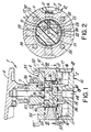
- the switching valve 1 of the present invention comprises a circular bottom plate 2, an intermediate plate 3 and a top plate 4.
- the bottom plate 2 has a bottom surface 10, a top surface 11, and a circular outer peripheral edge 12.
- the intermediate plate 3 has an upper surface 50, a lower surface 51, a circular outer peripheral edge 52 and a central interior circular opening 53 having a peripheral wall 59.
- the outer peripheral edge 52 may have a configuration other than circular without departing from the invention.
- the upper plate 4 has a lower surface 54, an upper surface 55 having an upstanding central attachment post 56 with a central shaft receiving opening 57 therein, and a circular outer peripheral edge 58.
- the configuration of the outer peripheral edge 58 may be other than circular if desired.
- Mounted within the central interior circular opening 53 in the intermediate plate 3 is a rotatable circular distributor 5 having an upper surface 60 interfacing with lower surface 54 of upper plate 4 and a lower surface 61 interfacing with upper surface 51 of lower plate 2.
- the distributor 5 has an outer circular peripheral edge which interfaces with peripheral wall 59 of opening 53 in intermediate plate 3.
- the distributor 5 is rotated by a knob 6 through the intermediation of a shaft 7 extending through the opening 57 and keyed to the distributor 5 by key and slot assembly 8 and 9 in upper surface 60 of the distributor 5.
- the three plates 2,3,4 are attached to each other and held together by bolts 38 or any other well-known fastening means.
- the lower surface wall 10 of the bottom plate 2 has an inlet opening 13 which is centrally located and which communicates with a centrally located inlet socket 14 which in turn communicates with a centrally located inlet conduit 15 extending upwardly to the upper surface 11 of bottom plate 2.
- a plurality of spaced outlets 16 each of which communicates with an outlet socket 17 which is oriented substantially parallel to the upper and lower surfaces 11 and 10 of the bottom plate 2 and substantially midway thereof.
- Each of the outlet sockets 17 communicates with an outlet conduit 18 of a smaller diameter which extends upwardly, preferably at right angles to the outlet conduits 18 to the upper surface 11 of the bottom plate 2.
- four such outlet assemblies (comprising outlet 16, outlet socket 17 and outlet conduit 18) are shown in evenly spaced relationship to each other around the periphery of the outer peripheral edge 12 of bottom plate 2.
- openings 13 and 16 and related pockets and conduits as inlets and outlets respectively hereinabove and hereinafter is for ease of description only.
- the openings 13 and 16 with related sockets and conduits may be outlets and inlets, respectively, without departing from the invention.
- the rotatable distributor 5 has a conduit assembly 20 which comprises vertical inlet conduit 21 and vertical outlet conduit 22 connected together by a horizontal connecting conduit 23.
- the vertical inlet conduit 20 is at the center of the distributor 5 and communicates with and is axially aligned with the upwardly extending centrally located inlet conduit 15 in the bottom plate 2.
- the vertical outlet conduit 22 is spaced from vertical inlet conduit 21 at the same distance as the distance between the inlet conduit 15 and outlet 18 in the bottom plate 2, so that when the distributor 2 is in the proper position, the vertical outlet conduit 22 in the distributor 5 will communicate with the outlet conduit 18 in the bottom plate 2 and the vertical inlet conduit 21 in distributor 5 communications with inlet conduit 15 in bottom plate 2 to complete a path between inlet 14 and outlet 16 through the intermediation of inlet conduits 15 and 21, horizontal connecting conduit 23 and outlet conduits 22 and 18.
- outlet conduit 22 is placed into communication with the next outlet conduit 18 in bottom plate 2 so that flow resumes.
- the valve switches from a flow condition to a non-flow condition and by the rotation of the knob 6 the fluid can flow from the inlet 13 through any of the outlets 16 depending on the position of the distributor 5.
- the unique seal construction of the valve of the present invention permits rotation of the distributor 5 without any danger of leakage.
- the upper surface 11 of the bottom plate 2 has a pair of spaced O-rings 30 and 31 which are located on each side of the outlet conduits 18 in the bottom plate 2. These o-rings 30 and 31 seal the interface between lower surface 61 of distributor 5 and the upper surface 11 of the bottom plate 2 and seal inlet conduits 15 and 21 and outlet conduits 22 and 18 so that no fluid can escape.
- the central plate 3 has o-rings 32 and 33 on its upper and lower surfaces 54 and 51, respectively, to seal the interface between upper and intermediate plates 4-3 and intermediate and lower plates 2 and 3, respectively, in order to avoid leakage.
- An o-ring 34 with associated spacer 35 thereabove is also provided around the shaft 7 adjacent the lower surface 54 of the top plate 4 to avoid leakage.
- the horizontal conduit 23 is formed from the outside peripheral edge 62 of the distributor 5 and a seal 36 is mounted therein to plug the horizontal connecting conduit 22 and prevent leakage.
- indentations 40 are formed in the lower of the top plate 4 and a spring-pressed lock ball 41 biased by spring 42 is formed in the distributor 5.
- the lock-ball 41 will snap into the indentation 40 and prevent further rotation of the distributor 5.
- FIG. 4 and 5 The embodiment in Figs. 4 and 5 is similar to the embodiment in Figs. 1 and 3. However, in this embodiment there are six outlets 16 with associated outlet sockets and outlet conduits (rather than the four in Figs. 1-3 embodiment) so that the distributor 5 may be moved between six positions. Otherwise the construction and operation of the embodiment shown in Figs. 4 and 5 is similar to the construction and operation of the embodiment shown in Figs. 1 to 3.
- the present invention provides an improved switching valve which will connect and disconnect an inlet to a plurality of outlets in which the valve is tightly sealed to prevent leakage, which is easy to operate, and
Landscapes
- Engineering & Computer Science (AREA)
- General Engineering & Computer Science (AREA)
- Mechanical Engineering (AREA)
- Multiple-Way Valves (AREA)
Applications Claiming Priority (2)
| Application Number | Priority Date | Filing Date | Title |
|---|---|---|---|
| US08/917,524 US5881770A (en) | 1997-08-26 | 1997-08-26 | Switching valve |
| US917524 | 1997-08-26 |
Publications (2)
| Publication Number | Publication Date |
|---|---|
| EP0899492A2 true EP0899492A2 (de) | 1999-03-03 |
| EP0899492A3 EP0899492A3 (de) | 2000-03-01 |
Family
ID=25438913
Family Applications (1)
| Application Number | Title | Priority Date | Filing Date |
|---|---|---|---|
| EP19980115987 Withdrawn EP0899492A3 (de) | 1997-08-26 | 1998-08-25 | Schaltventil |
Country Status (2)
| Country | Link |
|---|---|
| US (1) | US5881770A (de) |
| EP (1) | EP0899492A3 (de) |
Cited By (5)
| Publication number | Priority date | Publication date | Assignee | Title |
|---|---|---|---|---|
| RU2175735C1 (ru) * | 2001-01-25 | 2001-11-10 | Немытко Виктор Ефимович | Кран |
| RU2181173C2 (ru) * | 2000-06-26 | 2002-04-10 | Коллективное научно-производственное предприятие экологически чистых транспортных топлив КНПП "Экотранспал" | Заправочное устройство |
| EP1956276A1 (de) * | 2007-02-06 | 2008-08-13 | LuK Lamellen und Kupplungsbau Beteiligungs KG | Ventil mit einem Drehschieber und Rückschlagventilen |
| RU2349819C2 (ru) * | 2004-07-17 | 2009-03-20 | Жуньдэ ЯН | Универсальный клапан регулирования потока для систем водоподготовки |
| CN104100736A (zh) * | 2013-04-03 | 2014-10-15 | 贵州国台酒庄有限公司 | 一种酿制白酒用的分酒阀 |
Families Citing this family (17)
| Publication number | Priority date | Publication date | Assignee | Title |
|---|---|---|---|---|
| US6264891B1 (en) * | 1998-12-22 | 2001-07-24 | Eos Biotechnology, Inc. | Apparatus and method for concurrent chemical synthesis |
| WO2000045957A1 (en) * | 1999-02-05 | 2000-08-10 | Invitrogen Corporation | System, method and computer program product for automated fluid or gas delivery |
| US6725881B1 (en) * | 1999-02-26 | 2004-04-27 | Beswick Engineering, Inc. | Multi-port fluid valve and method |
| CN1128302C (zh) * | 1999-12-22 | 2003-11-19 | 梁荣康 | 一种水龙头 |
| CN1125934C (zh) * | 2000-12-11 | 2003-10-29 | 梁荣康 | 一种陶瓷水龙头 |
| US6557573B2 (en) * | 2001-02-06 | 2003-05-06 | Pgi International, Ltd. | Liquid fertilizer distribution system and method |
| USD497412S1 (en) | 2003-04-17 | 2004-10-19 | Mitsubishi Rayon Co., Ltd. | Switch valve for a water purifier |
| ITVR20040168A1 (it) * | 2004-10-25 | 2005-01-25 | C M Tecnologie S R L | Selettore, particolarmente ma non esclusivamente per distributori automatici di bevande |
| AU309186S (en) * | 2005-12-09 | 2006-08-25 | Buerkert Werke Gmbh | Switching valve |
| AU309210S (en) * | 2005-12-09 | 2006-08-25 | Buerkert Werke Gmbh | Switching valve |
| US7644728B2 (en) * | 2007-02-08 | 2010-01-12 | Tsai-Chen Yang | Splitter for faucets |
| CN104633179B (zh) * | 2013-11-07 | 2017-02-15 | 氟络塞尔特种阀门(苏州)有限公司 | 多对一集中控制阀门装置 |
| US10919750B2 (en) * | 2017-06-06 | 2021-02-16 | Pacific Packaging Machinery, Llc | Rotary filling machine |
| CA3098034A1 (en) * | 2018-05-18 | 2019-11-21 | Mogas Industries, Inc. | Multiport valve |
| US11867356B2 (en) * | 2020-12-10 | 2024-01-09 | Patriot Research Center, LLC | Rotary multi-port greasing valve |
| JP2024512975A (ja) | 2021-03-29 | 2024-03-21 | サンフラワー セラピューティクス,ピービーシー | 選択可能な流体カプラ |
| WO2023200784A1 (en) * | 2022-04-11 | 2023-10-19 | James Richard Myers | Pneumatic gauge and pressure control device and pneumatic system including same |
Family Cites Families (28)
| Publication number | Priority date | Publication date | Assignee | Title |
|---|---|---|---|---|
| US1784381A (en) * | 1927-11-28 | 1930-12-09 | Frank J O'stroske | Valve |
| US2075458A (en) * | 1935-09-13 | 1937-03-30 | Arthur L Parker | Disk valve assembly |
| US2091874A (en) * | 1936-05-21 | 1937-08-31 | Hughes Tool Co | Flow bean indicator |
| US2492140A (en) * | 1944-01-22 | 1949-12-27 | Thompson Prod Inc | Fluid flow control device |
| US2700984A (en) * | 1954-01-07 | 1955-02-01 | Vernon E Gleasman | Rotary control valve |
| US2893430A (en) * | 1954-09-16 | 1959-07-07 | James W F Holl | Noninterflow rotary valve |
| US2925095A (en) * | 1954-11-23 | 1960-02-16 | Alfred O Bates | Valve |
| US2974681A (en) * | 1956-07-18 | 1961-03-14 | Whitehurst George | Rotary fluid distributor valves |
| US2885179A (en) * | 1956-08-30 | 1959-05-05 | Hartmann Werner | Spherical ball valve |
| US2979963A (en) * | 1957-12-17 | 1961-04-18 | Borg Warner | Hydraulic clutch control |
| US3056426A (en) * | 1960-10-21 | 1962-10-02 | Hauser Fred | Distributors |
| US3236495A (en) * | 1963-03-25 | 1966-02-22 | Whitey Research Tool Co | Ball valve |
| US3387632A (en) * | 1966-04-08 | 1968-06-11 | M & J Valve Co | Meter prover and diverter valve therefor |
| US3554224A (en) * | 1969-07-11 | 1971-01-12 | Martonair Ltd | Fluid distribution valve |
| US3633621A (en) * | 1970-02-13 | 1972-01-11 | Robertshaw Controls Co | Snap-fitted pneumatic selector valve having a tubular conduit for fluid flow switching |
| US3687163A (en) * | 1970-12-07 | 1972-08-29 | Norgren Co C A | Selector valve with o-ring seals |
| US3735956A (en) * | 1972-04-10 | 1973-05-29 | Whitey Research Tool Co | Ball valve and improved seat arrangement |
| US3837360A (en) * | 1972-09-20 | 1974-09-24 | Caterpillar Tractor Co | Fluidic selector valve |
| US4294285A (en) * | 1978-12-14 | 1981-10-13 | Joslyn Larry J | Multi-port valve |
| US4410001A (en) * | 1980-02-05 | 1983-10-18 | Goguen Robert P | Anti-siphon selector valve |
| JPS5765463A (en) * | 1980-10-02 | 1982-04-21 | Fuji Kinzoku Kosaku Kk | Ball valve |
| US4538640A (en) * | 1982-02-24 | 1985-09-03 | Teledyne Republic Manufacturing | Multiposition selector valve |
| GB2164124A (en) * | 1984-09-04 | 1986-03-12 | Angar Scient Company Inc | Rotary valve |
| US4632149A (en) * | 1984-12-10 | 1986-12-30 | Uop Inc. | Rotary valve for interconnecting conduits |
| US4632148A (en) * | 1985-09-05 | 1986-12-30 | Stark Sr Robert G | Hydraulic distribution valve |
| US5261451A (en) * | 1991-05-02 | 1993-11-16 | General Electric Company | Pneumatic multiplexer |
| FR2685944B1 (fr) * | 1992-01-08 | 1995-05-19 | Snecma | Valve rotative de distribution de fluide et ensemble de valves en faisant application. |
| DK169928B1 (da) * | 1993-02-16 | 1995-04-03 | Verntofta Fjaederfae Ab | Fordelerventil til højtrykspumpe, især til sekvensvis fordeling af et trykmedie til flere forskellige udløb efter hinanden fra en og samme pumpe |
-
1997
- 1997-08-26 US US08/917,524 patent/US5881770A/en not_active Expired - Fee Related
-
1998
- 1998-08-25 EP EP19980115987 patent/EP0899492A3/de not_active Withdrawn
Non-Patent Citations (1)
| Title |
|---|
| None |
Cited By (5)
| Publication number | Priority date | Publication date | Assignee | Title |
|---|---|---|---|---|
| RU2181173C2 (ru) * | 2000-06-26 | 2002-04-10 | Коллективное научно-производственное предприятие экологически чистых транспортных топлив КНПП "Экотранспал" | Заправочное устройство |
| RU2175735C1 (ru) * | 2001-01-25 | 2001-11-10 | Немытко Виктор Ефимович | Кран |
| RU2349819C2 (ru) * | 2004-07-17 | 2009-03-20 | Жуньдэ ЯН | Универсальный клапан регулирования потока для систем водоподготовки |
| EP1956276A1 (de) * | 2007-02-06 | 2008-08-13 | LuK Lamellen und Kupplungsbau Beteiligungs KG | Ventil mit einem Drehschieber und Rückschlagventilen |
| CN104100736A (zh) * | 2013-04-03 | 2014-10-15 | 贵州国台酒庄有限公司 | 一种酿制白酒用的分酒阀 |
Also Published As
| Publication number | Publication date |
|---|---|
| US5881770A (en) | 1999-03-16 |
| EP0899492A3 (de) | 2000-03-01 |
Similar Documents
| Publication | Publication Date | Title |
|---|---|---|
| EP0899492A2 (de) | Schaltventil | |
| EP2267345B1 (de) | Ventil mit mehreren Anschlüssen | |
| US5293901A (en) | Double-control tap with selector | |
| US10745894B2 (en) | Universal embedded system for sanitary faucet components | |
| US5190077A (en) | Switchover valve | |
| JP2018100682A (ja) | 流路切換弁 | |
| US6367504B1 (en) | Multi-way stop or diverter valve | |
| JP3403389B2 (ja) | 多方向の閉塞又は方向転換バルブ | |
| KR20010088426A (ko) | 유동 전환기 조립체 | |
| US5839471A (en) | Sealing member for a valve | |
| CN102162528A (zh) | 用于分隔两种介质的径向轴密封装置 | |
| CA2111209C (en) | Mixer valve having a ball valve element | |
| US4972876A (en) | Liquid directional control valve | |
| US4716934A (en) | Connectors used in fluid techniques | |
| WO2004042220A2 (en) | Bypass valve | |
| US5325887A (en) | Connecting device for a sanitary appliance mixing valve | |
| GB2579183A (en) | Disc valve assembly | |
| US11236836B2 (en) | Actuating mechanism for actuating valves | |
| CN111434959B (zh) | 驱动机构 | |
| JP2017160927A (ja) | 流路切換弁 | |
| GB2209581A (en) | Fluid control valve | |
| AU724994B2 (en) | Discs for bi-flow mixer tap cartridges and cartridge including them | |
| CN222502784U (zh) | 多通阀 | |
| KR101530668B1 (ko) | 4방향 밸브 | |
| US3434498A (en) | Dual-passage line-breaking valve |
Legal Events
| Date | Code | Title | Description |
|---|---|---|---|
| PUAI | Public reference made under article 153(3) epc to a published international application that has entered the european phase |
Free format text: ORIGINAL CODE: 0009012 |
|
| AK | Designated contracting states |
Kind code of ref document: A2 Designated state(s): AT BE CH CY DE DK ES FI FR GB GR IE IT LI LU MC NL PT SE |
|
| AX | Request for extension of the european patent |
Free format text: AL;LT;LV;MK;RO;SI |
|
| PUAL | Search report despatched |
Free format text: ORIGINAL CODE: 0009013 |
|
| AK | Designated contracting states |
Kind code of ref document: A3 Designated state(s): AT BE CH CY DE DK ES FI FR GB GR IE IT LI LU MC NL PT SE |
|
| AX | Request for extension of the european patent |
Free format text: AL;LT;LV;MK;RO;SI |
|
| AKX | Designation fees paid | ||
| STAA | Information on the status of an ep patent application or granted ep patent |
Free format text: STATUS: THE APPLICATION IS DEEMED TO BE WITHDRAWN |
|
| 18D | Application deemed to be withdrawn |
Effective date: 20000902 |
|
| REG | Reference to a national code |
Ref country code: DE Ref legal event code: 8566 |