EP0899476B1 - Dämpfungselement, insbesondere zum Lagern der Stützscheibe eines Scheibenwischermechanismusses - Google Patents
Dämpfungselement, insbesondere zum Lagern der Stützscheibe eines Scheibenwischermechanismusses Download PDFInfo
- Publication number
- EP0899476B1 EP0899476B1 EP98116069A EP98116069A EP0899476B1 EP 0899476 B1 EP0899476 B1 EP 0899476B1 EP 98116069 A EP98116069 A EP 98116069A EP 98116069 A EP98116069 A EP 98116069A EP 0899476 B1 EP0899476 B1 EP 0899476B1
- Authority
- EP
- European Patent Office
- Prior art keywords
- block
- groove
- damping
- damping device
- face
- Prior art date
- Legal status (The legal status is an assumption and is not a legal conclusion. Google has not performed a legal analysis and makes no representation as to the accuracy of the status listed.)
- Expired - Lifetime
Links
Images

Classifications
-
- F—MECHANICAL ENGINEERING; LIGHTING; HEATING; WEAPONS; BLASTING
- F16—ENGINEERING ELEMENTS AND UNITS; GENERAL MEASURES FOR PRODUCING AND MAINTAINING EFFECTIVE FUNCTIONING OF MACHINES OR INSTALLATIONS; THERMAL INSULATION IN GENERAL
- F16F—SPRINGS; SHOCK-ABSORBERS; MEANS FOR DAMPING VIBRATION
- F16F1/00—Springs
- F16F1/36—Springs made of rubber or other material having high internal friction, e.g. thermoplastic elastomers
- F16F1/373—Springs made of rubber or other material having high internal friction, e.g. thermoplastic elastomers characterised by having a particular shape
- F16F1/376—Springs made of rubber or other material having high internal friction, e.g. thermoplastic elastomers characterised by having a particular shape having projections, studs, serrations or the like on at least one surface
-
- F—MECHANICAL ENGINEERING; LIGHTING; HEATING; WEAPONS; BLASTING
- F16—ENGINEERING ELEMENTS AND UNITS; GENERAL MEASURES FOR PRODUCING AND MAINTAINING EFFECTIVE FUNCTIONING OF MACHINES OR INSTALLATIONS; THERMAL INSULATION IN GENERAL
- F16F—SPRINGS; SHOCK-ABSORBERS; MEANS FOR DAMPING VIBRATION
- F16F1/00—Springs
- F16F1/36—Springs made of rubber or other material having high internal friction, e.g. thermoplastic elastomers
- F16F1/373—Springs made of rubber or other material having high internal friction, e.g. thermoplastic elastomers characterised by having a particular shape
- F16F1/3732—Springs made of rubber or other material having high internal friction, e.g. thermoplastic elastomers characterised by having a particular shape having an annular or the like shape, e.g. grommet-type resilient mountings
-
- B—PERFORMING OPERATIONS; TRANSPORTING
- B60—VEHICLES IN GENERAL
- B60S—SERVICING, CLEANING, REPAIRING, SUPPORTING, LIFTING, OR MANOEUVRING OF VEHICLES, NOT OTHERWISE PROVIDED FOR
- B60S1/00—Cleaning of vehicles
- B60S1/02—Cleaning windscreens, windows or optical devices
- B60S1/04—Wipers or the like, e.g. scrapers
- B60S1/043—Attachment of the wiper assembly to the vehicle
- B60S1/0441—Attachment of the wiper assembly to the vehicle characterised by the attachment means
- B60S1/0444—Attachment of the wiper assembly to the vehicle characterised by the attachment means comprising vibration or noise absorbing means
Definitions
- the invention relates to a damping device in particular for mounting a support plate for a wiper mechanism.
- the invention relates more particularly to a device shock absorber, in particular for mounting a support plate of a wiper mechanism, comprising a damper block which is provided with a central bore for the axial passage of a member assembly and which is mounted axially through an orifice of a plate element of the plate so that the edge of the hole is received in a radial groove arranged in a lateral surface external of the block, and in which the groove has two faces upper and lower transverse joined by a cylindrical face which is turned radially outwards.
- a damping device is known from the document EP-A-0 636 808.
- damping device it is possible example of fixing the plate of a wiper mechanism on the body of a vehicle.
- a screw is axially engaged at across the shock absorber block to clamp it against an element of body structure.
- the screw is therefore secured to the vehicle body but it is completely isolated from the plate, especially in terms of vibration, by the damping block which is generally produced made of elastomeric material.
- damping devices are highly prone to shear breaks at the bottom of the groove in the external lateral surface of the damping block. Indeed, under the effect of vibrations, the edge of the orifice of the plate which is received in this groove tends to degrade the elastomeric material relatively fragile and it can tear quickly.
- This phenomenon is accentuated when a cylindrical spacer tubular is engaged in the central bore of the damper block, radially interposed between the fixing member and the side wall of the bore, in order to limit the axial crushing of the damping block during tightening of the assembly member.
- the portion of the damping block which is included radially between the spacer and the edge of the orifice of the plate is then finds sheared between two elements which are rigid and which are independent of each other from the point of view of vibrations.
- the object of the invention is therefore to propose a new design of a shock-absorbing device which makes it possible to increase notably the lifetime of such a device.
- the invention proposed a damping device of the type described above, characterized in that the groove has a annular bead which extends radially outwards from the face cylindrical at the bottom of the groove and which cooperates with an edge face from the edge of the plate hole.
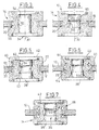
- FIG. 1 shows a damping device 10 of known type for mounting a plate element 12, for example example an element of a mechanism support plate wiping on a body structure of a motor vehicle.
- the device 10 essentially comprises a damping block 14, which is of generally cylindrical tubular axis revolution A1, and which is engaged axially through an orifice 16 of the element plate 12.
- the edge 18 of the orifice 16 is engaged in a groove 20 arranged radially inwards in a surface cylindrical outer side 22 of the damper block 14.
- the block 14 is thus immobilized axially and radially by relative to the orifice 16 and it thus comprises an upper portion 24 arranged above the plate 12 and a lower portion 26 arranged below it.
- the groove 20 is delimited radially inwards by a cylindrical bottom face 28 which is turned radially outwards and it is axially delimited by two upper transverse faces 30 and lower 32 parallel and opposite.
- the damper block 14 includes a central bore 34 for the passage of an assembly member (not shown) such as a screw.
- the purpose of this assembly member is to tighten axially the damping block on the second element to which must be connected plate 12.
- a tubular spacer 36 which is axially engaged in the central bore 34, interposed radially between the assembly member and the damping block.
- the spacer 34 has, at a lower axial end, a collar external radial 38 and it is intended to cooperate, at its end upper 40, with an annular washer 42 so that the washer 42 and radial collar 38 form bearing surfaces, by example for the head of the screw and for the second element on which must be fixed the plate 12.
- the radial collar 38 and the washer 42 are received in counterbores 44 arranged in transverse faces axial end 46 of the damper block 14 so that the collar 38 and the washer 42 are substantially flush with these faces 46.
- Figure 2 a first embodiment of the invention.
- the edge 18 of the orifice 16 does not bear directly against the bottom face 28 of the throat 20.
- the latter comprises a bead 48 which extends radially outward, preferably over the entire periphery of the groove 20, to cooperate in radial support with a face edge 50 of the edge 18 of the orifice 16 of the plate 12.
- the bead 48 has a dimension, according to the direction axial of the damper block 14, which is less than that of the groove 20 and therefore less than the thickness of the plate 12. In this way, the edge 18 orifice 16 is no longer in contact with the intersection zones of the face bottom 28 of the groove 20 with the transverse faces 30, 32 of this groove 20 which are particularly fragile areas where generally the initiation of tearing due to shearing forces.
- the block shock absorber further comprises a clearance 52 which is formed in a cylindrical side wall 54 of the central bore 16 of the damper block 14.
- This clearance 52 is arranged axially in correspondence with the groove 20 so that a middle portion 56 of the block shock absorber 14, between its upper 24 and lower portions 26, has a certain flexibility in the radial direction by relative to axis A1, which limits the risk of tearing elastomeric material.
- the clearance 52 is for example in the form of an arc of a circle, preferably of radius large enough not to constitute a too abrupt variation in the thickness of the middle portion 56 of the block 14.
- the clearance 52 also makes it possible to limit the compression of the material constituting the damping block 14 when it is axially tightened by the assembly member.
- the device damper 10 further comprises an annular groove 58 which is arranged in an external cylindrical face 60 of the spacer 36, axially in correspondence with groove 20 and with the clearance 52 of the damping block 14.
- This groove 58 which extends annularly around the axis A1, for example also has a section in relatively large radius arc shape.
- the damper block 14 illustrated in FIG. 6 has a recess 64 which is arranged at the intersection of the face of bottom 28 with each of the transverse faces 30, 32 of the groove 20 and which extends annularly over the entire circumference of the groove 20.
- one or more (s) can be provided point (s) of the circumference a rib which extends in the recess 64 and which allows better retention of the bead 48.
- This rib (or these ribs) can (can) also allow the centering of the shock absorber 14.
- FIG. 7 shows a damper block 14 which is made in two parts 66, 68, both parts being integral with each other but being made in elastomeric materials of different hardness.
- a first part 66 is in contact with the spacer 36 and its external radial collar 38 while a second part 68 is in contact with the plate 12 and the washer 42.
- the second part 68 is thus arranged radially outward relative to the first part 66 and the groove 20 is entirely arranged in the second part 68.
Landscapes
- Engineering & Computer Science (AREA)
- General Engineering & Computer Science (AREA)
- Mechanical Engineering (AREA)
- Springs (AREA)
- Vibration Dampers (AREA)
- Fluid-Damping Devices (AREA)
Claims (9)
- Dämpfervorrichtung, insbesondere für die Montage einer Tragplatine (12) eines Scheibenwischer-Mechanismus, mit einem Dämpferblock (14), der mit einer mittleren Bohrung (34) versehen ist, für die axiale Durchführung eines Montageorgans, und der axial durch eine Öffnung (16) eines Plattenelements (12) der Platine montiert ist, so dass der Rand (18) der Öffnung (16) in einem an einer externen Seitenfläche (22) des Blocks (14) vorgesehenen radialen Hals (20) aufgenommen wird, und bei dem der Hals (20) eine obere (30) und eine untere (32) Querfläche aufweist, die durch eine zylindrische Bodenfläche (28) vereint werden, die radial nach außen gerichtet ist, dadurch gekennzeichnet, dass der Hals (20) einen ringförmigen Wulst (48) aufweist, der sich von der zylindrischen Bodenfläche (28) des Halses (20) aus radial nach außen erstreckt, und der mit einer Kantenfläche (50) des Rands (18) der Öffnung (16) der Platte (12) zusammenwirkt.
- Dämpfervorrichtung nach Anspruch 1, dadurch gekennzeichnet, dass der Dämpferblock (14) eine ringförmige Aussparung (64) umfasst, die am Schnittpunkt der Bodenfläche (28) und einer der Querflächen (30, 32) des Halses (20) vorgesehen ist.
- Dämpfervorrichtung nach Anspruch 2, dadurch gekennzeichnet, dass der Dämpferblock (14) zwei Aussparungen (64) umfasst, die auf beiden Seiten des Wulstes (48) am Schnittpunkt der Bodenfläche (28) und jeder der Querflächen (30, 32) des Halses (20) vorgesehen sind.
- Dämpfervorrichtung nach einem der vorherigen Ansprüche, dadurch gekennzeichnet, dass der Schnittpunkt der externen Seitenfläche (22) des Blocks (14) mit einer der Querflächen (30, 32) des Halses (20) abgerundet ist.
- Dämpfervorrichtung nach einem der vorherigen Ansprüche, dadurch gekennzeichnet, dass die mittlere Bohrung (34) des Dämpferblocks (14) eine Seitenwand (54) umfasst, in der ein ringförmiger Freiraum (52) vorgesehen ist, der axial mit dem in der externen Seitenfläche (22) des Blocks (14) vorgesehenen Hals (20) in Verbindung steht.
- Dämpfervorrichtung nach einem der vorherigen Ansprüche, dadurch gekennzeichnet, dass in die mittlere Bohrung (34) des Dämpferblocks (14) ein rohrförmiger Steg (36) eingeführt ist, so dass er radial zwischen dem Montageorgan und einer Seitenwand (54) der Bohrung (34) des Blocks (14) liegt, und dass der Steg (36) eine ringförmige, axial angeordnete Rille (58) in Verbindung mit dem in der externen Seitenfläche (22) des Blocks (14) vorgesehenen Hals (20) umfasst.
- Dämpfervorrichtung nach einem der vorherigen Ansprüche, dadurch gekennzeichnet, dass zumindest eines der axialen Enden (62) einer Seitenwand (54) der mittleren Bohrung (34) des Dämpferblocks (14) abgerundet ist.
- Dämpfervorrichtung nach einem der vorherigen Ansprüche, dadurch gekennzeichnet, dass der Dämpferblock (14) aus einem Elastomer-Material besteht.
- Dämpfervorrichtung nach einem der vorherigen Ansprüche, dadurch gekennzeichnet, dass der Dämpferblock (14) aus zwei Teilen (66, 68) besteht, die miteinander verbunden sind und aus Elastomer-Materialien unterschiedlicher Härten bestehen.
Applications Claiming Priority (2)
| Application Number | Priority Date | Filing Date | Title |
|---|---|---|---|
| FR9710877 | 1997-08-29 | ||
| FR9710877A FR2767768B1 (fr) | 1997-08-29 | 1997-08-29 | Dispositif amortisseur notamment pour le montage d'une platine de support d'un mecanisme d'essuie-glace |
Publications (2)
| Publication Number | Publication Date |
|---|---|
| EP0899476A1 EP0899476A1 (de) | 1999-03-03 |
| EP0899476B1 true EP0899476B1 (de) | 2003-04-23 |
Family
ID=9510665
Family Applications (1)
| Application Number | Title | Priority Date | Filing Date |
|---|---|---|---|
| EP98116069A Expired - Lifetime EP0899476B1 (de) | 1997-08-29 | 1998-08-26 | Dämpfungselement, insbesondere zum Lagern der Stützscheibe eines Scheibenwischermechanismusses |
Country Status (4)
| Country | Link |
|---|---|
| EP (1) | EP0899476B1 (de) |
| DE (1) | DE69813699T2 (de) |
| ES (1) | ES2198623T3 (de) |
| FR (1) | FR2767768B1 (de) |
Families Citing this family (10)
| Publication number | Priority date | Publication date | Assignee | Title |
|---|---|---|---|---|
| IT1320612B1 (it) * | 2000-08-31 | 2003-12-10 | Gomma C F Spa | Supporto elastico antivibrante e procedimento per la definizione dellesue caratteristiche. |
| FR2855577B1 (fr) * | 2003-05-28 | 2005-07-15 | Peugeot Citroen Automobiles Sa | Dispositif amortisseur de vibrations. |
| DE202004004610U1 (de) * | 2004-03-24 | 2004-07-29 | Trw Automotive Gmbh | Gummilager, insbesondere für ein Motorpumpenaggregat einer Servolenkung |
| EP3045762B1 (de) * | 2015-01-14 | 2019-03-13 | Volvo Car Corporation | Elastisch verformbarer Dämpfer |
| EP3464929B1 (de) * | 2016-05-27 | 2020-07-15 | Basf Se | Federelement für einen fahrzeugstossdämpfer, sowie fahrzeugstossdämpfer und verwendung dieses federelement |
| DE102017209624A1 (de) * | 2017-06-08 | 2018-12-13 | Robert Bosch Gmbh | Entkopplungselement |
| CA3073282A1 (en) * | 2017-08-21 | 2019-02-28 | Bae Systems Plc | Anti-vibration mount |
| DE102019113663B4 (de) * | 2019-05-10 | 2022-10-06 | Illinois Tool Works Inc. | Abstandhalter für eine befestigungsanordnung, befestigungsanordnung mit einem solchen abstandhalter sowie verfahren zum befestigen eines montageteils an einem trägerteil |
| DE102022106955A1 (de) * | 2022-03-24 | 2023-09-28 | Bayerische Motoren Werke Aktiengesellschaft | Schwingungsentkoppelungshülse sowie Befestigungsvorrichtung mit einer Schwingungsentkoppelungshülse |
| CN115163744B (zh) * | 2022-09-07 | 2024-01-16 | 万向钱潮股份公司 | 一种固定减震装置及其安装方法 |
Family Cites Families (6)
| Publication number | Priority date | Publication date | Assignee | Title |
|---|---|---|---|---|
| US3350042A (en) * | 1965-10-11 | 1967-10-31 | Clevite Corp | Corrugated resilient mount |
| DE1943764A1 (de) * | 1969-08-28 | 1971-03-11 | Continental Gummi Werke Ag | Elastisches Lager fuer Motoraufhaengung in Kraftfahrzeugen |
| DE2121677A1 (de) * | 1971-05-03 | 1972-11-16 | Continental Gummi-Werke Ag, 3000 Hannover | Elastisches Lager, insbesondere für die Motoraufhängung in Kraftfahrzeugen |
| GB1555429A (en) * | 1976-11-15 | 1979-11-07 | Caterpillar Tractor Co | Mouting grommet |
| DE4325250C1 (de) * | 1993-07-28 | 1995-02-16 | Freudenberg Carl Fa | Halter zur schwingungsentkoppelten Befestigung von einem im wesentlichen plattenförmigen Maschinenelement |
| FR2727478B1 (fr) * | 1994-11-30 | 1997-04-04 | Valeo Systemes Dessuyage | Dispositif pour la fixation d'un element sur la caisse d'un vehicule automobile |
-
1997
- 1997-08-29 FR FR9710877A patent/FR2767768B1/fr not_active Expired - Lifetime
-
1998
- 1998-08-26 DE DE69813699T patent/DE69813699T2/de not_active Expired - Lifetime
- 1998-08-26 ES ES98116069T patent/ES2198623T3/es not_active Expired - Lifetime
- 1998-08-26 EP EP98116069A patent/EP0899476B1/de not_active Expired - Lifetime
Also Published As
| Publication number | Publication date |
|---|---|
| ES2198623T3 (es) | 2004-02-01 |
| DE69813699D1 (de) | 2003-05-28 |
| FR2767768A1 (fr) | 1999-03-05 |
| FR2767768B1 (fr) | 1999-10-08 |
| EP0899476A1 (de) | 1999-03-03 |
| DE69813699T2 (de) | 2003-12-18 |
Similar Documents
| Publication | Publication Date | Title |
|---|---|---|
| EP0715086B1 (de) | Anordnung zur Befestigung eines Elementes an einer Kraftfahrzeugkarosserie | |
| EP0899476B1 (de) | Dämpfungselement, insbesondere zum Lagern der Stützscheibe eines Scheibenwischermechanismusses | |
| FR2918138A1 (fr) | Butee de suspension comprenant un element d'etancheite mobile. | |
| FR2830911A1 (fr) | Articulation hydroelastique rotulee | |
| EP0751305A1 (de) | Anordnung zur Befestigung eines Elementes von einem Scheibenwischer an einer Kraftfahrzeugkarrosserie | |
| FR2928187A1 (fr) | Dispositif de butee de suspension et jambe de force | |
| EP0156697A1 (de) | Änderungen an hydraulischen Antischwingungslagern | |
| WO1998022343A1 (fr) | Joint d'articulation automoteur, auto-verrouillant et amortissant et articulation equipee de tels joints | |
| FR2901737A1 (fr) | Dispositif de butee de suspension et jambe de force | |
| FR2818718A1 (fr) | Manchon antivibratoire et vehicule automobile comportant un tel manchon | |
| EP0660006B1 (de) | Dynamisches Resonatorelement und sein Montageverfahren | |
| FR2708060A1 (fr) | Agencement de palier pour un arbre tournant appartenant à un mécanisme d'entraînement d'un essuie-glace. | |
| EP0879971B1 (de) | Vorrichtung zur Befestigung einer Anordnung an einer Kraftfahrzeugkarosserie und Wischermodul mit einer derartigen Vorrichtung | |
| FR2910383A1 (fr) | Butee de suspension pourvue d'une coupelle et procede de fabrication d'une butee de suspension. | |
| FR2754024A1 (fr) | Soufflet de transmission pour un vehicule automobile et son procede de remplacement | |
| EP0225227A1 (de) | Änderungen an hydraulischen Anti-Schwingungslagern | |
| FR2898170A1 (fr) | "support de suspension a organes elastiques de nature differentes" | |
| EP0679559B1 (de) | Scheibenwischermechanismus mit einer verbesserten Gelenkverbindung zwischen einer Kurbel und einer Gelenkstange des Mechanismus | |
| FR2572485A1 (fr) | Joint plat | |
| FR2740518A1 (fr) | Palier compressible axialement pour un mecanisme d'essuie-glace | |
| FR2774340A1 (fr) | Mecanisme d'essuie-glace de vehicule automobile | |
| FR2909743A1 (fr) | Joint d'etancheite. | |
| WO2003029703A1 (fr) | Joint de culasse comprenant un stoppeur bord a bord lie par agrafage | |
| FR2764952A1 (fr) | Systeme d'entrainement pour un essuie-glace de vehicule automobile comportant une articulation a rotule perfectionnee | |
| EP1293701B1 (de) | Schwingungsdämpfendes Lager und Schwingungsdämpfungseinrichtung mit solchem Lager |
Legal Events
| Date | Code | Title | Description |
|---|---|---|---|
| PUAI | Public reference made under article 153(3) epc to a published international application that has entered the european phase |
Free format text: ORIGINAL CODE: 0009012 |
|
| AK | Designated contracting states |
Kind code of ref document: A1 Designated state(s): DE ES FR GB IT |
|
| AX | Request for extension of the european patent |
Free format text: AL;LT;LV;MK;RO;SI |
|
| 17P | Request for examination filed |
Effective date: 19990831 |
|
| AKX | Designation fees paid |
Free format text: DE ES FR GB IT |
|
| GRAH | Despatch of communication of intention to grant a patent |
Free format text: ORIGINAL CODE: EPIDOS IGRA |
|
| GRAH | Despatch of communication of intention to grant a patent |
Free format text: ORIGINAL CODE: EPIDOS IGRA |
|
| GRAA | (expected) grant |
Free format text: ORIGINAL CODE: 0009210 |
|
| AK | Designated contracting states |
Designated state(s): DE ES FR GB IT |
|
| REG | Reference to a national code |
Ref country code: GB Ref legal event code: FG4D Free format text: NOT ENGLISH |
|
| REF | Corresponds to: |
Ref document number: 69813699 Country of ref document: DE Date of ref document: 20030528 Kind code of ref document: P |
|
| PGFP | Annual fee paid to national office [announced via postgrant information from national office to epo] |
Ref country code: GB Payment date: 20030819 Year of fee payment: 6 |
|
| GBT | Gb: translation of ep patent filed (gb section 77(6)(a)/1977) |
Effective date: 20030730 |
|
| REG | Reference to a national code |
Ref country code: ES Ref legal event code: FG2A Ref document number: 2198623 Country of ref document: ES Kind code of ref document: T3 |
|
| PLBE | No opposition filed within time limit |
Free format text: ORIGINAL CODE: 0009261 |
|
| STAA | Information on the status of an ep patent application or granted ep patent |
Free format text: STATUS: NO OPPOSITION FILED WITHIN TIME LIMIT |
|
| 26N | No opposition filed |
Effective date: 20040126 |
|
| PG25 | Lapsed in a contracting state [announced via postgrant information from national office to epo] |
Ref country code: GB Free format text: LAPSE BECAUSE OF NON-PAYMENT OF DUE FEES Effective date: 20040826 |
|
| GBPC | Gb: european patent ceased through non-payment of renewal fee |
Effective date: 20040826 |
|
| REG | Reference to a national code |
Ref country code: FR Ref legal event code: PLFP Year of fee payment: 19 |
|
| PGFP | Annual fee paid to national office [announced via postgrant information from national office to epo] |
Ref country code: DE Payment date: 20160817 Year of fee payment: 19 Ref country code: IT Payment date: 20160818 Year of fee payment: 19 |
|
| PGFP | Annual fee paid to national office [announced via postgrant information from national office to epo] |
Ref country code: FR Payment date: 20160831 Year of fee payment: 19 |
|
| PGFP | Annual fee paid to national office [announced via postgrant information from national office to epo] |
Ref country code: ES Payment date: 20160830 Year of fee payment: 19 |
|
| REG | Reference to a national code |
Ref country code: DE Ref legal event code: R119 Ref document number: 69813699 Country of ref document: DE |
|
| REG | Reference to a national code |
Ref country code: FR Ref legal event code: ST Effective date: 20180430 |
|
| PG25 | Lapsed in a contracting state [announced via postgrant information from national office to epo] |
Ref country code: DE Free format text: LAPSE BECAUSE OF NON-PAYMENT OF DUE FEES Effective date: 20180301 |
|
| PG25 | Lapsed in a contracting state [announced via postgrant information from national office to epo] |
Ref country code: IT Free format text: LAPSE BECAUSE OF NON-PAYMENT OF DUE FEES Effective date: 20170826 Ref country code: FR Free format text: LAPSE BECAUSE OF NON-PAYMENT OF DUE FEES Effective date: 20170831 |
|
| REG | Reference to a national code |
Ref country code: ES Ref legal event code: FD2A Effective date: 20181024 |
|
| PG25 | Lapsed in a contracting state [announced via postgrant information from national office to epo] |
Ref country code: ES Free format text: LAPSE BECAUSE OF NON-PAYMENT OF DUE FEES Effective date: 20170827 |