EP0899476B1 - Damping element, in particular for the mounting of a windscreen wiper mechanism support plate - Google Patents
Damping element, in particular for the mounting of a windscreen wiper mechanism support plate Download PDFInfo
- Publication number
- EP0899476B1 EP0899476B1 EP98116069A EP98116069A EP0899476B1 EP 0899476 B1 EP0899476 B1 EP 0899476B1 EP 98116069 A EP98116069 A EP 98116069A EP 98116069 A EP98116069 A EP 98116069A EP 0899476 B1 EP0899476 B1 EP 0899476B1
- Authority
- EP
- European Patent Office
- Prior art keywords
- block
- groove
- damping
- damping device
- face
- Prior art date
- Legal status (The legal status is an assumption and is not a legal conclusion. Google has not performed a legal analysis and makes no representation as to the accuracy of the status listed.)
- Expired - Lifetime
Links
Images

Classifications
-
- F—MECHANICAL ENGINEERING; LIGHTING; HEATING; WEAPONS; BLASTING
- F16—ENGINEERING ELEMENTS AND UNITS; GENERAL MEASURES FOR PRODUCING AND MAINTAINING EFFECTIVE FUNCTIONING OF MACHINES OR INSTALLATIONS; THERMAL INSULATION IN GENERAL
- F16F—SPRINGS; SHOCK-ABSORBERS; MEANS FOR DAMPING VIBRATION
- F16F1/00—Springs
- F16F1/36—Springs made of rubber or other material having high internal friction, e.g. thermoplastic elastomers
- F16F1/373—Springs made of rubber or other material having high internal friction, e.g. thermoplastic elastomers characterised by having a particular shape
- F16F1/376—Springs made of rubber or other material having high internal friction, e.g. thermoplastic elastomers characterised by having a particular shape having projections, studs, serrations or the like on at least one surface
-
- F—MECHANICAL ENGINEERING; LIGHTING; HEATING; WEAPONS; BLASTING
- F16—ENGINEERING ELEMENTS AND UNITS; GENERAL MEASURES FOR PRODUCING AND MAINTAINING EFFECTIVE FUNCTIONING OF MACHINES OR INSTALLATIONS; THERMAL INSULATION IN GENERAL
- F16F—SPRINGS; SHOCK-ABSORBERS; MEANS FOR DAMPING VIBRATION
- F16F1/00—Springs
- F16F1/36—Springs made of rubber or other material having high internal friction, e.g. thermoplastic elastomers
- F16F1/373—Springs made of rubber or other material having high internal friction, e.g. thermoplastic elastomers characterised by having a particular shape
- F16F1/3732—Springs made of rubber or other material having high internal friction, e.g. thermoplastic elastomers characterised by having a particular shape having an annular or the like shape, e.g. grommet-type resilient mountings
-
- B—PERFORMING OPERATIONS; TRANSPORTING
- B60—VEHICLES IN GENERAL
- B60S—SERVICING, CLEANING, REPAIRING, SUPPORTING, LIFTING, OR MANOEUVRING OF VEHICLES, NOT OTHERWISE PROVIDED FOR
- B60S1/00—Cleaning of vehicles
- B60S1/02—Cleaning windscreens, windows or optical devices
- B60S1/04—Wipers or the like, e.g. scrapers
- B60S1/043—Attachment of the wiper assembly to the vehicle
- B60S1/0441—Attachment of the wiper assembly to the vehicle characterised by the attachment means
- B60S1/0444—Attachment of the wiper assembly to the vehicle characterised by the attachment means comprising vibration or noise absorbing means
Description
L'invention concerne un dispositif amortisseur notamment pour le montage d'une platine de support d'un mécanisme d'essuie-glace.The invention relates to a damping device in particular for mounting a support plate for a wiper mechanism.
L'invention concerne plus particulièrement un dispositif amortisseur, notamment pour le montage d'une platine de support d'un mécanisme d'essuie-glace, comportant un bloc amortisseur qui est pourvu d'un alésage central pour le passage axial d'un organe d'assemblage et qui est monté axialement au travers d'un orifice d'un élément de plaque de la platine de telle sorte que le bord de l'orifice est reçu dans une gorge radiale aménagée dans une surface latérale externe du bloc, et dans lequel la gorge comporte deux faces transversales supérieure et inférieure réunies par une face cylindrique de fond qui est tournée radialement vers l'extérieur. Un tel dispositif amortisseur est connu du document EP-A-0 636 808.The invention relates more particularly to a device shock absorber, in particular for mounting a support plate of a wiper mechanism, comprising a damper block which is provided with a central bore for the axial passage of a member assembly and which is mounted axially through an orifice of a plate element of the plate so that the edge of the hole is received in a radial groove arranged in a lateral surface external of the block, and in which the groove has two faces upper and lower transverse joined by a cylindrical face which is turned radially outwards. Such a damping device is known from the document EP-A-0 636 808.
Grâce à un tel type de dispositif amortisseur, il est par exemple possible de fixer la platine d'un mécanisme d'essuie-glace sur la caisse d'un véhicule. Par exemple, une vis est engagée axialement au travers du bloc amortisseur pour serrer celui-ci contre un élément de structure de la caisse. La vis est donc solidaire de la caisse du véhicule mais elle se trouve complètement isolée de la platine, notamment en termes de vibration, par le bloc amortisseur qui est généralement réalisé en matériau élastomère.Thanks to such a type of damping device, it is possible example of fixing the plate of a wiper mechanism on the body of a vehicle. For example, a screw is axially engaged at across the shock absorber block to clamp it against an element of body structure. The screw is therefore secured to the vehicle body but it is completely isolated from the plate, especially in terms of vibration, by the damping block which is generally produced made of elastomeric material.
On s'est aperçu que de tels dispositifs amortisseurs étaient fortement sujets à des ruptures par cisaillement au niveau du fond de la gorge aménagée dans la surface latérale externe du bloc amortisseur. En effet, sous l'effet des vibrations, le bord de l'orifice de la plaque qui est reçu dans cette gorge tend à dégrader le matériau élastomère relativement fragile et celui-ci peut se déchirer rapidement.It has been found that such damping devices are highly prone to shear breaks at the bottom of the groove in the external lateral surface of the damping block. Indeed, under the effect of vibrations, the edge of the orifice of the plate which is received in this groove tends to degrade the elastomeric material relatively fragile and it can tear quickly.
Ce phénomène est accentué lorsqu'une entretoise cylindrique tubulaire est engagée dans l'alésage central du bloc amortisseur, interposée radialement entre l'organe de fixation et la paroi latérale de l'alésage, afin de limiter l'écrasement axial du bloc amortisseur lors du serrage de l'organe d'assemblage.This phenomenon is accentuated when a cylindrical spacer tubular is engaged in the central bore of the damper block, radially interposed between the fixing member and the side wall of the bore, in order to limit the axial crushing of the damping block during tightening of the assembly member.
En effet, la portion du bloc amortisseur qui est comprise radialement entre l'entretoise et le bord de l'orifice de la platine se trouve alors cisaillée entre deux éléments qui sont rigides et qui sont indépendants l'un de l'autre du point de vue des vibrations.Indeed, the portion of the damping block which is included radially between the spacer and the edge of the orifice of the plate is then finds sheared between two elements which are rigid and which are independent of each other from the point of view of vibrations.
L'invention a donc pour objet de proposer une nouvelle conception d'un dispositif amortisseur qui permette d'augmenter notablement la durée de vie d'un tel dispositif.The object of the invention is therefore to propose a new design of a shock-absorbing device which makes it possible to increase notably the lifetime of such a device.
A cet effet, l'invention proposé un dispositif amortisseur du type décrit précédemment, caractérisé en ce que la gorge comporte un bourrelet annulaire qui s'étend radialement vers l'extérieur depuis la face cylindrique de fond de la gorge et qui coopère avec une face de chant du bord de l'orifice de la plaque.To this end, the invention proposed a damping device of the type described above, characterized in that the groove has a annular bead which extends radially outwards from the face cylindrical at the bottom of the groove and which cooperates with an edge face from the edge of the plate hole.
Selon d'autres caractéristiques de l'invention :
- le bloc amortisseur comporte un évidement annulaire qui est aménagé à l'intersection de la face de fond et de l'une des faces transversales de la gorge ;
- le bloc amortisseur comporte deux évidements agencés de part et d'autre du bourrelet à l'intersection de la face de fond et de chacune des faces transversales de la gorge ;
- l'intersection de la face latérale externe du bloc avec l'une des faces transversales de la gorge est arrondie ;
- l'alésage central du bloc amortisseur comporte une paroi latérale dans laquelle est aménagé un dégagement annulaire axialement en correspondance avec la gorge aménagée dans la surface latérale externe du bloc ;
- une entretoise tubulaire est engagée dans l'alésage central du bloc amortisseur de manière à être interposée radialement entre l'organe d'assemblage et une paroi latérale de l'alésage du bloc, et l'entretoise comporte une rainure annulaire agencée axialement en correspondance avec la gorge aménagée dans la surface latérale externe du bloc ;
- l'une au moins des extrémités axiales d'une paroi latérale de l'alésage central du bloc amortisseur est arrondie ;
- le bloc amortisseur est réalisé en matériau élastomère ;
- le bloc amortisseur est réalisé en deux parties qui sont solidaires l'une de l'autre et qui sont réalisées dans des matériaux élastomères de duretés différentes.
- the damping block has an annular recess which is arranged at the intersection of the bottom face and one of the transverse faces of the groove;
- the damping block has two recesses arranged on either side of the bead at the intersection of the bottom face and each of the transverse faces of the groove;
- the intersection of the external lateral face of the block with one of the transverse faces of the groove is rounded;
- the central bore of the damping block has a side wall in which is provided an annular clearance axially corresponding to the groove formed in the external lateral surface of the block;
- a tubular spacer is engaged in the central bore of the damper block so as to be interposed radially between the assembly member and a side wall of the bore of the block, and the spacer comprises an annular groove arranged axially in correspondence with the groove arranged in the external lateral surface of the block;
- at least one of the axial ends of a side wall of the central bore of the damper block is rounded;
- the damping block is made of elastomeric material;
- the damping block is made in two parts which are integral with one another and which are made of elastomeric materials of different hardness.
D'autres caractéristiques et avantages de l'invention apparaítront à la lecture de la description détaillée qui suit pour la compréhension de laquelle on se reportera aux dessins annexés dans lesquels :
- la figure 1 est une vue schématique partielle en perspective et avec arrachement d'un dispositif amortisseur selon l'état de la technique ; et
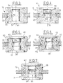
- les figures 2 à 7 sont des vues en coupe axiale de six modes de réalisation d'un dispositif amortisseur conforme aux enseignements de l'invention.
- Figure 1 is a partial schematic perspective view with cutaway of a damping device according to the prior art; and
- Figures 2 to 7 are views in axial section of six embodiments of a damping device according to the teachings of the invention.
On a représenté sur la figure 1 un dispositif amortisseur 10 de
type connu pour assurer le montage d'un élément de plaque 12, par
exemple un élément d'une platine de support d'un mécanisme
d'essuyage sur une structure de caisse d'un véhicule automobile.FIG. 1 shows a
Le dispositif 10 comporte essentiellement un bloc amortisseur
14, qui est de forme générale cylindrique tubulaire de révolution d'axe
A1, et qui est engagé axialement au travers d'un orifice 16 de l'élément
de plaque 12. A cet effet, le bord 18 de l'orifice 16 est engagé dans une
gorge 20 aménagée radialement vers l'intérieur dans une surface
latérale externe cylindrique 22 du bloc amortisseur 14.The
Le bloc 14 est ainsi immobilisé axialement et radialement par
rapport à l'orifice 16 et il comporte ainsi une portion supérieure 24
agencée au-dessus de la plaque 12 et une portion inférieure 26 agencée
en dessous de celle-ci.The
La gorge 20 est délimitée radialement vers l'intérieur par une
face cylindrique de fond 28 qui est tournée radialement vers l'extérieur
et elle est délimitée axialement par deux faces transversales supérieure
30 et inférieure 32 parallèles et en vis-à-vis.The
De manière connue, le bloc amortisseur 14 comporte un
alésage central 34 pour le passage d'un organe d'assemblage (non
représenté) tel qu'une vis. Cet organe d'assemblage a pour but de serrer
axialement le bloc amortisseur sur le deuxième élément auquel doit être
reliée la platine 12.In known manner, the
Toutefois, pour limiter l'écrasement axial du bloc amortisseur
14, il est généralement prévu une entretoise tubulaire 36 qui est
engagée axialement dans l'alésage central 34, interposée radialement
entre l'organe d'assemblage et le bloc amortisseur.However, to limit the axial crushing of the
Dans l'exemple de réalisation illustré sur les figures,
l'entretoise 34 comporte, à une extrémité axiale inférieure, un collet
radial externe 38 et elle est destinée à coopérer, à son extrémité
supérieure 40, avec une rondelle annulaire 42 de telle manière que la
rondelle 42 et le collet radial 38 forment des surfaces d'appui, par
exemple pour la tête de la vis et pour le second élément sur lequel doit
être fixée la platine 12.In the embodiment illustrated in the figures,
the
De manière avantageuse, le collet radial 38 et la rondelle 42
sont reçus dans des lamages 44 aménagés dans des faces transversales
d'extrémité axiale 46 du bloc amortisseur 14 de telle manière que le
collet 38 et la rondelle 42 affleurent sensiblement au niveau de ces
faces 46.Advantageously, the
On a représenté sur la figure 2 un premier mode de réalisation
de l'invention. Comme on peut le voir sur cette figure, le bord 18 de
l'orifice 16 n'est pas en appui directement contre la face de fond 28 de
la gorge 20. En effet, cette dernière comporte un bourrelet 48 qui
s'étend radialement vers l'extérieur, de préférence sur toute la
périphérie de la gorge 20, pour coopérer en appui radial avec une face
de chant 50 du bord 18 de l'orifice 16 de la plaque 12.There is shown in Figure 2 a first embodiment
of the invention. As can be seen in this figure, the
Le bourrelet 48 présente une dimension, selon la direction
axiale du bloc amortisseur 14, qui est inférieure à celle de la gorge 20
et donc inférieure à l'épaisseur de la plaque 12. De la sorte, le bord 18
de l'orifice 16 n'est plus au contact des zones d'intersection de la face
de fond 28 de la gorge 20 avec les faces transversales 30, 32 de cette
gorge 20 qui sont des zones particulièrement fragiles où se réalise
généralement l'amorce de déchirure due aux efforts de cisaillement.The
Dans l'exemple de réalisation de la figure 3, le bloc
amortisseur comporte en plus un dégagement 52 qui est formé dans une
paroi latérale 54 cylindrique de l'alésage central 16 du bloc amortisseur
14. Ce dégagement 52 est aménagé axialement en correspondance avec
la gorge 20 de manière à ce qu'une portion médiane 56 du bloc
amortisseur 14, comprise entre ses portions supérieure 24 et inférieure
26, présente une certaine souplesse selon la direction radiale par
rapport à l'axe A1, ce qui permet de limiter les risques de déchirements
du matériau élastomère.In the embodiment of Figure 3, the block
shock absorber further comprises a
Le dégagement 52 est par exemple en forme d'arc de cercle,
de préférence de rayon suffisamment grand pour ne pas constituer une
variation trop brutale de l'épaisseur de la portion médiane 56 du bloc 14.The
Le dégagement 52 permet par ailleurs de limiter la
compression du matériau constituant le bloc amortisseur 14 lorsque
celui-ci est serré axialement par l'organe d'assemblage.The
Dans l'exemple de réalisation de la figure 4, le dispositif
amortisseur 10 comporte de plus une rainure annulaire 58 qui est
aménagée dans une face cylindrique externe 60 de l'entretoise 36,
axialement en correspondance avec la gorge 20 et avec le dégagement
52 du bloc amortisseur 14. Cette rainure 58, qui s'étend annulairement
autour de l'axe A1, présente par exemple elle aussi une section en
forme d'arc de cercle de relativement grand rayon.In the embodiment of FIG. 4, the
Dans l'exemple de réalisation de la figure 5, il est prévu que
les extrémités axiales de la paroi latérale 54 de l'alésage central 34 du
bloc amortisseur 14, qui débouchent dans chacun des deux lamages 44,
soient arrondies et non pas à angle droit. Il en de même pour
l'intersection 61 de la face latérale externe 22 du bloc 14 avec chacune
des faces transversales 30, 32 de la gorge 20, ainsi que pour les bords
63 d'extrémité axiale de cette face latérale 22.In the embodiment of Figure 5, it is expected that
the axial ends of the
En supprimant les angles vifs du bloc amortisseur 14,
notamment au niveau des éventuelles zones de contact avec les
composants rigides que sont l'entretoise 36, la rondelle 42 et la platine
12, on limite les contraintes dans le matériau élastomère qui constitue le
bloc 14, et on limite surtout les zones de concentration de contraintes
où s'amorcent généralement les déchirures. By removing the sharp corners of the
Toujours dans ce but, le bloc amortisseur 14 illustré à la figure
6 comporte un évidement 64 qui est agencé à l'intersection de la face de
fond 28 avec chacune des faces transversales 30, 32 de la gorge 20 et
qui s'étend annulairement sur toute la circonférence de la gorge 20.Still for this purpose, the
Avantageusement, on peut prévoir en un ou plusieur(s)
point(s) de la circonférence une nervure qui s'étend dans l'évidement 64
et qui permet un meilleur maintien du bourrelet 48. Cette nervure (ou
ces nervures) peut (peuvent) également permettre le centrage de
l'amortisseur 14.Advantageously, one or more (s) can be provided
point (s) of the circumference a rib which extends in the
Enfin, l'exemple de réalisation illustré à la figure 7 montre un
bloc amortisseur 14 qui est réalisé en deux parties 66, 68, les deux
parties étant solidaires l'une de l'autre mais étant réalisées dans des
matériaux élastomères de duretés différentes.Finally, the embodiment illustrated in FIG. 7 shows a
A titre d'exemple, une première partie 66 est au contact de
l'entretoise 36 et de son collet radial externe 38 tandis qu'une seconde
partie 68 est au contact de la plaque 12 et de la rondelle 42. La seconde
partie 68 est ainsi agencée radialement vers l'extérieur par rapport à la
première partie 66 et la gorge 20 est aménagée entièrement dans la
seconde partie 68.For example, a first part 66 is in contact with
the
A titre d'exemple, on peut choisir alors de réaliser la première partie en un matériau plus dur que la seconde partie.As an example, we can then choose to carry out the first part made of a harder material than the second part.
Bien entendu, les différentes caractéristiques qui caractérisent les modes de réalisations de l'invention qui viennent d'être décrits peuvent être combinées entre elles pour donner encore d'autres modes de réalisation qui ne sont pas illustrés mais qui entrent bien entendu dans le champ de l'invention.Of course, the different characteristics that characterize the embodiments of the invention which have just been described can be combined to give other modes which are not illustrated but which of course enter within the scope of the invention.
Claims (9)
- A damping device, in particular for mounting a support platen (12) of a windscreen wiper mechanism, comprising a damping block (14) which is provided with a central bore (34) for the axial passage of an assembly member which is mounted axially through an orifice (16) in a plate element (12) of the platen so that the edge (18) of the orifice (16) is received in a radial groove (20) formed in an external lateral surface (22) of the block (14), and in which the groove (20) has two top (30) and bottom (32) transverse faces joined by a cylindrical bottom face (28) which is turned radially outwards,
characterised in that the groove (20) comprises an annular protrusion (48) which extends radially outwards from the bottom cylindrical face (28) of the groove (20) and which cooperates with an edge face (50) of the edge (18) of the orifice (16) in the plate (12). - A damping device according to Claim 1, characterised in that the damping block (14) comprises an annular recess (64) which is provided at the intersection of the bottom face (28) and one of the transverse faces (30, 32) of the groove (20).
- A damping device according to Claim 2, characterised in that the damping block (14) has two recesses (64) arranged on each side of the protrusion (48) at the intersection of the bottom face (28) and of each of the transverse faces (30, 32) of the groove (20).
- A damping device according to any one of the preceding claims, characterised in that the intersection of the external lateral face (22) of the block (14) with one of the transverse faces (30, 32) of the groove (20) is rounded.
- A damping device according to any one of the preceding claims, characterised in that the central bore (34) in the damping block (14) comprises a lateral wall (54) in which there is provided an annular space (52) axially in correspondence with the groove (20) formed in the external lateral surface (22) of the block (14).
- A damping device according to any one of the preceding claims, characterised in that a tubular strut (36) is engaged in the central bore (34) in the damping block (14) so as to be interposed radially between the assembly member and a lateral wall (54) of the bore (34) in the block (14), and in that the strut (36) comprises an annular groove (58) arranged axially in correspondence with the groove (20) provided in the external lateral surface (22) of the block (14).
- A damping device according to any one of the preceding claims, characterised in that at least one of the axial ends (62) of a lateral wall (54) of the central bore (34) in the damping block (14) is rounded.
- A damping device according to any one of the preceding claims, characterised in that the damping block (14) is produced from elastomer material.
- A damping device according to any one of the preceding claims, characterised in that the damping block (14) is produced in two parts (66, 68) which are fixed to each other and which are produced from elastomer materials with different hardnesses.
Applications Claiming Priority (2)
| Application Number | Priority Date | Filing Date | Title |
|---|---|---|---|
| FR9710877 | 1997-08-29 | ||
| FR9710877A FR2767768B1 (en) | 1997-08-29 | 1997-08-29 | DAMPING DEVICE, PARTICULARLY FOR MOUNTING A SUPPORT PLATE OF A WINDSCREEN WIPER MECHANISM |
Publications (2)
| Publication Number | Publication Date |
|---|---|
| EP0899476A1 EP0899476A1 (en) | 1999-03-03 |
| EP0899476B1 true EP0899476B1 (en) | 2003-04-23 |
Family
ID=9510665
Family Applications (1)
| Application Number | Title | Priority Date | Filing Date |
|---|---|---|---|
| EP98116069A Expired - Lifetime EP0899476B1 (en) | 1997-08-29 | 1998-08-26 | Damping element, in particular for the mounting of a windscreen wiper mechanism support plate |
Country Status (4)
| Country | Link |
|---|---|
| EP (1) | EP0899476B1 (en) |
| DE (1) | DE69813699T2 (en) |
| ES (1) | ES2198623T3 (en) |
| FR (1) | FR2767768B1 (en) |
Families Citing this family (10)
| Publication number | Priority date | Publication date | Assignee | Title |
|---|---|---|---|---|
| IT1320612B1 (en) * | 2000-08-31 | 2003-12-10 | Gomma C F Spa | ANTI-VIBRATION ELASTIC SUPPORT AND PROCEDURE FOR DEFINING ITS CHARACTERISTICS. |
| FR2855577B1 (en) * | 2003-05-28 | 2005-07-15 | Peugeot Citroen Automobiles Sa | SHOCK ABSORBER DEVICE. |
| DE202004004610U1 (en) * | 2004-03-24 | 2004-07-29 | Trw Automotive Gmbh | Rubber bearings, in particular for a motor pump unit of a power steering |
| EP3045762B1 (en) * | 2015-01-14 | 2019-03-13 | Volvo Car Corporation | Elastically deformable damper |
| US10920843B2 (en) * | 2016-05-27 | 2021-02-16 | Basf Se | Spring element for a vehicle shock absorber, and vehicle shock absorber and vehicle having same |
| DE102017209624A1 (en) * | 2017-06-08 | 2018-12-13 | Robert Bosch Gmbh | decoupling element |
| CA3073282A1 (en) * | 2017-08-21 | 2019-02-28 | Bae Systems Plc | Anti-vibration mount |
| DE102019113663B4 (en) * | 2019-05-10 | 2022-10-06 | Illinois Tool Works Inc. | SPACER FOR A FIXING ASSEMBLY, FIXING ASSEMBLY WITH SUCH SPACER, AND METHOD FOR ATTACHING A MOUNTING PART TO A SUPPORT PART |
| DE102022106955A1 (en) * | 2022-03-24 | 2023-09-28 | Bayerische Motoren Werke Aktiengesellschaft | Vibration decoupling sleeve and fastening device with a vibration decoupling sleeve |
| CN115163744B (en) * | 2022-09-07 | 2024-01-16 | 万向钱潮股份公司 | Fixed damping device and installation method thereof |
Family Cites Families (6)
| Publication number | Priority date | Publication date | Assignee | Title |
|---|---|---|---|---|
| US3350042A (en) * | 1965-10-11 | 1967-10-31 | Clevite Corp | Corrugated resilient mount |
| DE1943764A1 (en) * | 1969-08-28 | 1971-03-11 | Continental Gummi Werke Ag | Elastic bearing for engine suspension in motor vehicles |
| DE2121677A1 (en) * | 1971-05-03 | 1972-11-16 | Continental Gummi-Werke Ag, 3000 Hannover | Elastic mount, in particular for the engine suspension in motor vehicles |
| GB1555429A (en) * | 1976-11-15 | 1979-11-07 | Caterpillar Tractor Co | Mouting grommet |
| DE4325250C1 (en) * | 1993-07-28 | 1995-02-16 | Freudenberg Carl Fa | Holder for vibration-decoupled attachment of an essentially plate-shaped machine element |
| FR2727478B1 (en) * | 1994-11-30 | 1997-04-04 | Valeo Systemes Dessuyage | DEVICE FOR FIXING AN ELEMENT ON THE BODY OF A MOTOR VEHICLE |
-
1997
- 1997-08-29 FR FR9710877A patent/FR2767768B1/en not_active Expired - Lifetime
-
1998
- 1998-08-26 EP EP98116069A patent/EP0899476B1/en not_active Expired - Lifetime
- 1998-08-26 DE DE69813699T patent/DE69813699T2/en not_active Expired - Lifetime
- 1998-08-26 ES ES98116069T patent/ES2198623T3/en not_active Expired - Lifetime
Also Published As
| Publication number | Publication date |
|---|---|
| EP0899476A1 (en) | 1999-03-03 |
| FR2767768A1 (en) | 1999-03-05 |
| DE69813699D1 (en) | 2003-05-28 |
| ES2198623T3 (en) | 2004-02-01 |
| DE69813699T2 (en) | 2003-12-18 |
| FR2767768B1 (en) | 1999-10-08 |
Similar Documents
| Publication | Publication Date | Title |
|---|---|---|
| EP0715086B1 (en) | Device for fastening an element on a body of a motor vehicle | |
| EP0899476B1 (en) | Damping element, in particular for the mounting of a windscreen wiper mechanism support plate | |
| FR2918138A1 (en) | SUSPENSION STOP COMPRISING A MOBILE SEALING ELEMENT. | |
| FR2830911A1 (en) | Hydroelastic articulated joint for damping transmission vibrations has two elastically deformable elements of different lengths | |
| FR2936580A1 (en) | STOPPER OF SUSPENSION AND LEG OF ASSOCIATED FORCE | |
| EP0751305A1 (en) | Device for fastening an element of a windscreen wiper on a body of a motor vehicle | |
| FR2934656A1 (en) | SUSPENSION STOP DEVICE AND FORCE LEG. | |
| FR2928187A1 (en) | SUSPENSION STOPPER DEVICE AND FORCE LEG | |
| WO1998022343A1 (en) | Automotive, self-locking and damping articulated joint and articulation equipped with same | |
| FR2901737A1 (en) | SUSPENSION STOPPER DEVICE AND FORCE LEG | |
| FR2818718A1 (en) | ANTI-VIBRATION SLEEVE AND MOTOR VEHICLE COMPRISING SUCH A SLEEVE | |
| FR2708060A1 (en) | Bearing arrangement for a rotating shaft belonging to a drive mechanism of a wiper. | |
| EP0660006A1 (en) | Resonating dynamic damping element and its assembly | |
| EP0879971B1 (en) | Device for fastening an assembly to an automotive vehicle body and wiper module with such a device | |
| FR2910383A1 (en) | Bump stop for MacPherson strut, has support element and metallic mount with fixation reliefs, pin and traversing orifice for assuring fixation of mount with element by deformation of mount or element | |
| FR2754024A1 (en) | Flexible boot for vehicle transmission unit | |
| EP0225227A1 (en) | Modifications of hydraulic anti-vibration mountings | |
| FR2898170A1 (en) | Suspension support for strengthening a connection and filtering between body shell and the suspension of a vehicle, comprises a main framework and a secondary framework forming lid that surrounds an interior space of the frameworks | |
| EP0771958B1 (en) | Axially compressible bearing for a windscreen wiper mechanism | |
| EP0679559B1 (en) | Windscreen wiper mechanism with an improved pivot joint between a link rod and a crank of the mechanism | |
| FR2572485A1 (en) | FLAT JOINT | |
| FR2774340A1 (en) | Windscreen wiper mechanism for automobile | |
| FR2909743A1 (en) | SEAL SEAL. | |
| WO2003029703A1 (en) | Cylinder-head gasket comprising an edge-to-edge stop ring which is connected by means of stapling | |
| FR2764952A1 (en) | Motor vehicle windscreen wiper drive ball joint |
Legal Events
| Date | Code | Title | Description |
|---|---|---|---|
| PUAI | Public reference made under article 153(3) epc to a published international application that has entered the european phase |
Free format text: ORIGINAL CODE: 0009012 |
|
| AK | Designated contracting states |
Kind code of ref document: A1 Designated state(s): DE ES FR GB IT |
|
| AX | Request for extension of the european patent |
Free format text: AL;LT;LV;MK;RO;SI |
|
| 17P | Request for examination filed |
Effective date: 19990831 |
|
| AKX | Designation fees paid |
Free format text: DE ES FR GB IT |
|
| GRAH | Despatch of communication of intention to grant a patent |
Free format text: ORIGINAL CODE: EPIDOS IGRA |
|
| GRAH | Despatch of communication of intention to grant a patent |
Free format text: ORIGINAL CODE: EPIDOS IGRA |
|
| GRAA | (expected) grant |
Free format text: ORIGINAL CODE: 0009210 |
|
| AK | Designated contracting states |
Designated state(s): DE ES FR GB IT |
|
| REG | Reference to a national code |
Ref country code: GB Ref legal event code: FG4D Free format text: NOT ENGLISH |
|
| REF | Corresponds to: |
Ref document number: 69813699 Country of ref document: DE Date of ref document: 20030528 Kind code of ref document: P |
|
| PGFP | Annual fee paid to national office [announced via postgrant information from national office to epo] |
Ref country code: GB Payment date: 20030819 Year of fee payment: 6 |
|
| GBT | Gb: translation of ep patent filed (gb section 77(6)(a)/1977) |
Effective date: 20030730 |
|
| REG | Reference to a national code |
Ref country code: ES Ref legal event code: FG2A Ref document number: 2198623 Country of ref document: ES Kind code of ref document: T3 |
|
| PLBE | No opposition filed within time limit |
Free format text: ORIGINAL CODE: 0009261 |
|
| STAA | Information on the status of an ep patent application or granted ep patent |
Free format text: STATUS: NO OPPOSITION FILED WITHIN TIME LIMIT |
|
| 26N | No opposition filed |
Effective date: 20040126 |
|
| PG25 | Lapsed in a contracting state [announced via postgrant information from national office to epo] |
Ref country code: GB Free format text: LAPSE BECAUSE OF NON-PAYMENT OF DUE FEES Effective date: 20040826 |
|
| GBPC | Gb: european patent ceased through non-payment of renewal fee |
Effective date: 20040826 |
|
| REG | Reference to a national code |
Ref country code: FR Ref legal event code: PLFP Year of fee payment: 19 |
|
| PGFP | Annual fee paid to national office [announced via postgrant information from national office to epo] |
Ref country code: DE Payment date: 20160817 Year of fee payment: 19 Ref country code: IT Payment date: 20160818 Year of fee payment: 19 |
|
| PGFP | Annual fee paid to national office [announced via postgrant information from national office to epo] |
Ref country code: FR Payment date: 20160831 Year of fee payment: 19 |
|
| PGFP | Annual fee paid to national office [announced via postgrant information from national office to epo] |
Ref country code: ES Payment date: 20160830 Year of fee payment: 19 |
|
| REG | Reference to a national code |
Ref country code: DE Ref legal event code: R119 Ref document number: 69813699 Country of ref document: DE |
|
| REG | Reference to a national code |
Ref country code: FR Ref legal event code: ST Effective date: 20180430 |
|
| PG25 | Lapsed in a contracting state [announced via postgrant information from national office to epo] |
Ref country code: DE Free format text: LAPSE BECAUSE OF NON-PAYMENT OF DUE FEES Effective date: 20180301 |
|
| PG25 | Lapsed in a contracting state [announced via postgrant information from national office to epo] |
Ref country code: IT Free format text: LAPSE BECAUSE OF NON-PAYMENT OF DUE FEES Effective date: 20170826 Ref country code: FR Free format text: LAPSE BECAUSE OF NON-PAYMENT OF DUE FEES Effective date: 20170831 |
|
| REG | Reference to a national code |
Ref country code: ES Ref legal event code: FD2A Effective date: 20181024 |
|
| PG25 | Lapsed in a contracting state [announced via postgrant information from national office to epo] |
Ref country code: ES Free format text: LAPSE BECAUSE OF NON-PAYMENT OF DUE FEES Effective date: 20170827 |