EP0899464A2 - Ensemble hydraulique de régulation d'un servomoteur - Google Patents
Ensemble hydraulique de régulation d'un servomoteur Download PDFInfo
- Publication number
- EP0899464A2 EP0899464A2 EP98116235A EP98116235A EP0899464A2 EP 0899464 A2 EP0899464 A2 EP 0899464A2 EP 98116235 A EP98116235 A EP 98116235A EP 98116235 A EP98116235 A EP 98116235A EP 0899464 A2 EP0899464 A2 EP 0899464A2
- Authority
- EP
- European Patent Office
- Prior art keywords
- hydraulic motor
- hydraulic
- rotational speed
- control assembly
- motor
- Prior art date
- Legal status (The legal status is an assumption and is not a legal conclusion. Google has not performed a legal analysis and makes no representation as to the accuracy of the status listed.)
- Withdrawn
Links
Images

Classifications
-
- F—MECHANICAL ENGINEERING; LIGHTING; HEATING; WEAPONS; BLASTING
- F15—FLUID-PRESSURE ACTUATORS; HYDRAULICS OR PNEUMATICS IN GENERAL
- F15B—SYSTEMS ACTING BY MEANS OF FLUIDS IN GENERAL; FLUID-PRESSURE ACTUATORS, e.g. SERVOMOTORS; DETAILS OF FLUID-PRESSURE SYSTEMS, NOT OTHERWISE PROVIDED FOR
- F15B9/00—Servomotors with follow-up action, e.g. obtained by feed-back control, i.e. in which the position of the actuated member conforms with that of the controlling member
- F15B9/14—Servomotors with follow-up action, e.g. obtained by feed-back control, i.e. in which the position of the actuated member conforms with that of the controlling member with rotary servomotors
-
- F—MECHANICAL ENGINEERING; LIGHTING; HEATING; WEAPONS; BLASTING
- F15—FLUID-PRESSURE ACTUATORS; HYDRAULICS OR PNEUMATICS IN GENERAL
- F15B—SYSTEMS ACTING BY MEANS OF FLUIDS IN GENERAL; FLUID-PRESSURE ACTUATORS, e.g. SERVOMOTORS; DETAILS OF FLUID-PRESSURE SYSTEMS, NOT OTHERWISE PROVIDED FOR
- F15B15/00—Fluid-actuated devices for displacing a member from one position to another; Gearing associated therewith
- F15B15/20—Other details, e.g. assembly with regulating devices
- F15B15/28—Means for indicating the position, e.g. end of stroke
- F15B15/2815—Position sensing, i.e. means for continuous measurement of position, e.g. LVDT
Definitions
- This invention concerns a hydraulic servomotor control assembly such as a hydraulic servomotor control assembly which supplies the pressurized fluid for example oil, air, water, etc. as operating fluid to a hydraulic motor, and controls the volume of the pressurized fluid by means of a servo valve.
- a hydraulic servomotor control assembly such as a hydraulic servomotor control assembly which supplies the pressurized fluid for example oil, air, water, etc. as operating fluid to a hydraulic motor, and controls the volume of the pressurized fluid by means of a servo valve.
- FIG. 5 is a block diagram of an existing hydraulic servomotor control assembly for controlling the rotational speed of a load through the use of a hydraulic motor.
- 34 is a hydraulic motor driven by fluid supplied from fluid source 32 via servo valve 33
- 36 is the load driven by the hydraulic motor 34.
- hydraulic motor 34 is connected to fluid source 32 via the servo valve 33.
- the rotational speed of hydraulic motor 34 is controlled by means of an input signal which is input to servo valve 33.
- the rotation of the output shaft of the hydraulic motor 34 is transmitted through gears 37, which are affixed to the output shaft, to tachogenerator 35, whose purpose is to detect the rotational speed.
- the tachogenerator 35 outputs a voltage which is proportional to the rotational speed of hydraulic motor 34.
- 31 is a control device which calculates and outputs a signal to control the servo valve 33 based on the voltage signals output by the tachogenerator 35 and on the rotational speed 30 which has been prescribed.
- Hydraulic motor 34 can thus function as a servomotor.
- the hydraulic motor 34 In hydraulic servomotors of the prior art, the hydraulic motor 34, on the one hand, and the tachogenerator 35 or mechanism for detecting the rotation, on the other hand, are two separate entities.
- a mechanism 35 for detecting the speed of rotation i.e., a tachogenerator
- a hydraulic motor 34 with a cylinder 30 mm in diameter is used for output control, the device (tachogenerator) 35 for detecting the speed of rotation will be about the same size as motor 34. This makes the servomotor quite large, and it is difficult to find ways to make it any smaller.
- prior art servomotors are subject to backlash and chattering due to the gears, belt and/or chain used to transmit the rotation from the motor to the speed detector. This causes them to be less rigid and may result in vibration.
- the object of the present invention is to provide a hydraulic servomotor control assembly, comprising a hydraulic motor and a rotation detector, which is smaller in size and yet has a greater capacity.
- the means for transmitting the rotation would not produce backlash or chattering, so the control function would be enhanced.
- the hydraulic servomotor control assembly is distinguished by the following configuration.
- a rotational speed detector device i.e. a rotational detecting means
- the speed sensor may be placed either on the peripheral surface of the rotor or adjacent its external periphery.
- the rotational speed detector device for directly detecting rotational speed is built into the hydraulic motor of the hydraulic servomotor control assembly, and is shaft coupled with the output shaft of the hydraulic motor.
- the rotor may be either the rotating coil element in a tachogenerator, the disk plate in an optical rotary encoder, or the magnetic ring in a magnetic rotary encoder.
- the rotational speed sensor for detecting the rotation according to this invention can be either the magnetic element in a tachogenerator, the photointerrupter in an optical rotary encoder, or the Hole IC in a magnetic rotary encoder.
- a rotational speed detector device for detecting rotational speed which comprises a tachogenerator or an optical or mechanical encoder, is mounted directly on the output shaft of a hydraulic motor. Because the rotational speed detector device is integral to and within the hydraulic motor, the motor assembly is considerably smaller than prior art devices in which the hydraulic motor and the means for detecting rotation were separate units.
- the rotor comprising the rotational speed detector device is mounted directly on the output shaft of the hydraulic motor, there is no backlash or chattering as occurred with prior art devices due to the means required to transmit rotation from the motor to the speed detector. Thus there is no loss of rigidity in control and no vibration, so the control function is enhanced.
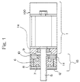
- Figure 1 shows the configuration of a hydraulic servomotor assembly in which the motor and the tachogenerator have been integrated in a single package.
- This motor assembly is the first preferred embodiment of this invention.
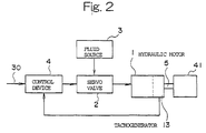
- Figure 2 is a block diagram of a hydraulic servomotor control assembly employing the hydraulic servomotor of Figure 1.
- the hydraulic motor 1 is connected to fluid source 3 by way of servo valve 2.
- the rotational speed of hydraulic motor 1 is controlled according to signals input to the servo valve 2.
- the rotation of output shaft 5 of the hydraulic motor 1 is transmitted directly to tachogenerator 13 which is shaft coupled with the hydraulic motor 1.
- Tachogenerator 13 outputs a voltage which is proportional to the rotational speed of hydraulic motor 1.
- the control device 4 Based on the voltage signal output by tachogenerator 13 and the predetermined input signal for rotational speed 30, the control device 4 calculates and outputs a signal to control servo valve 2.
- Hydraulic motor assembly 100 shown in Figure 1, comprises hydraulic motor 1 and tachogenerator 13, which are integrated into a single machine through their common connection to output shaft 5, and shaft coupled to each other.
- Rotating element 6 of tachogenerator 13 is affixed to the periphery of output shaft 5, which extends outward from the hydraulic motor 1.
- Rotating element 6 contains a coil 7 around which an insulated electrical wire is wrapped. The ends of the wire on the coil 7 are connected to commutator 9, which is separately insulated above the rotating element 6.
- a ring-shaped magnetic element 8 is fixed to the interior of the cover 12 so that it faces the exterior of the rotating element 6.
- hydraulic motor 1 is driven to rotate by the fluid supplied from fluid source 3 via servo valve 2.
- Output shaft 5 rotates, causing rotating element 6 of tachogenerator 13, which is attached to the shaft, to rotate as well.
- the magnetic element 8 generates a fixed magnetic field whose field lines run along the diameter of output shaft 5. Thus, when the rotating element 6 rotates, both element 6 and coil 7 are rotating within this fixed magnetic field. This rotation generates electromotive force in both ends of the electrical wire on coil 7.
- the voltage at either end of the electrical wire on coil 7 varies sinusoidally with the relative angle of coil 7 with respect to the fixed magnetic field.
- Commutator 9 is placed so that the ends of the wire on coil 7 and brushes 10 and 11 are connected during the period when this voltage has straight polarity; it rectifies the voltage.
- a voltage proportional to the speed of rotation of the rotating shaft i.e., output shaft 5
- This output signal is transmitted to control device 4 (shown in Figure 2) as the signal representing the detected rotational speed (i.e., r.p.m.) of hydraulic motor 1.
- hydraulic motor 1 and the tachogenerator are housed separately.
- the rotation of motor 1 must be transmitted to the tachogenerator through gears, a belt and/or a chain, and space must be provided for the tachogenerator to be placed outside the motor.
- tachogenerator 13 is mounted directly on output shaft 5 of hydraulic motor 1 and housing 1a.
- Hydraulic motor assembly 100 which comprises both motor 1 and tachogenerator 13, is much smaller than the aforedescribed prior art device. Spatial limitations in the assembly of motor 1 have been eliminated, thus increasing the freedom with which hydraulic motor assembly 100 may be designed.
- This design allows a servomotor assembly to be produced which is smaller and has greater output than an electromagnetic servomotor assembly of the prior art.
- the motor Because the rotor (i.e., rotating element 6) of tachogenerator 13 is mounted directly on output shaft 5 of the hydraulic motor 1, the motor has no backlash or chattering caused by the means for transmitting the rotation, as occurred with prior art motors. Thus it is not subject to a loss of rigidity in the control assembly or vibration, and its control capabilities are enhanced.
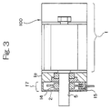
- FIG. 3 shows the configuration of another hydraulic motor assembly, which is a second preferred embodiment of this invention.
- hydraulic motor assembly 100 has an incremental-type optical encoder 17 which is integral with output shaft 5 of hydraulic motor 1.
- Encoder 17 consists primarily of encoder disk 14, photointerrupter 15 and cover 12.
- encoder disk 14 is mounted on the exterior surface of output shaft (rotary shaft) 5, which extends outward from hydraulic motor 1.
- Cover 12 of the optical rotary encoder 17 is attached to housing 1a of the motor 1 by means of a bolt (not shown).
- Photointerrupter 15 which has a two-phase output, is mounted on the interior of the cover 12.
- Encoder disk 14 is attached to rotary shaft 5 of hydraulic motor 1 in such a way as to interrupt the optical path of photointerrupter 15.
- a number of pulses proportional to the speed of rotation of motor 1 is output by interrupter 15 when hydraulic servo motor assembly 100 is operating.
- a second set of pulses, phase-shifted from the first set by a specified amount, is used to detect the direction of rotation. By counting the number of pulses per unit time, the speed of rotation of hydraulic motor 1 can be calculated.
- optical rotary encoder 17 is mounted directly on output shaft 5 of hydraulic motor 1.
- Motor assembly 100 which consists of the hydraulic motor 1 and optical rotary encoder 17, is smaller than similar assemblies of the prior art. Spatial limitations in the assembly of motor 1 which existed in the prior art have been eliminated, thus increasing the freedom with which hydraulic motor assembly 100 may be designed.
- This design allows a servomotor assembly to be produced which is smaller and has greater output than an electromagnetic servomotor of the prior art.
- the first embodiment discussed above measures only the speed of rotation of hydraulic motor 1. This embodiment cumulates the pulse output as well, so it can also detect the angle of rotation of motor 1. It can thus be used to control the position of the load.
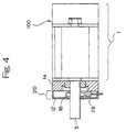
- FIG. 4 shows the configuration of a hydraulic motor assembly which is a third preferred embodiment of this invention.
- hydraulic motor assembly 100 a ringshaped magnetic element 18 is attached to output shaft 5 of hydraulic motor 1.
- Magnetic element 18 is polarized so that it has a given number of poles along the direction of its perimeter.
- Placing Hole IC 19 adjacent the periphery of ring 18 creates magnetic rotary encoder 20.
- Hydraulic motor 1 and the rotary encoder 20 form an integral entity, in which encoder 20 serves to detect the speed of rotation of the motor 1.
- magnetic ring 18 which has been polarized so that it has a given number of poles along the direction of its perimeter, is mounted on the exterior surface of output shaft (rotary shaft) 5, which extends outward from hydraulic motor 1.
- Cover 12 of the rotary encoder 20 is attached to housing 1a of the motor 1 by means of a bolt (not shown).
- Hole IC 19 is attached to cover 12 so that it faces the outer edge of the magnetic ring 18 and can detect the passage of its poles during rotation.
- magnetic rotary encoder 20 is mounted directly on output shaft 5 of hydraulic motor 1.
- Motor assembly 100 which comprises hydraulic motor 1 and magnetic rotary encoder 20, is smaller than similar devices of the prior art. Spatial limitations in the assembly of motor 1 which existed in the prior art have been eliminated, thus increasing the freedom with which hydraulic motor assembly 100 may be designed.
- This design allows a servomotor assembly to be produced which is smaller and has greater output than an electromagnetic servomotor of the prior art.
- the pulse generator requires few structural components, and its configuration is simpler than in the prior art.
- an incrementaltype rotary encoder 17 ( Figure 3) or a magnetic rotary encoder 20 may as an alternative be mounted on the supporting end (on the right in Figures 3 and 4) of hydraulic motor 1.
- lubricating oil is the optimal choice for an operating fluid for the hydraulic servomotor assembly, air or some other pressurized fluid could also be used.
Landscapes
- Engineering & Computer Science (AREA)
- Physics & Mathematics (AREA)
- Fluid Mechanics (AREA)
- Mechanical Engineering (AREA)
- General Engineering & Computer Science (AREA)
- Hydraulic Motors (AREA)
- Servomotors (AREA)
- Actuator (AREA)
Applications Claiming Priority (3)
| Application Number | Priority Date | Filing Date | Title |
|---|---|---|---|
| JP25126797A JPH1182417A (ja) | 1997-09-01 | 1997-09-01 | 流体サーボモータ装置 |
| JP25126797 | 1997-09-01 | ||
| JP251267/97 | 1997-09-01 |
Publications (2)
| Publication Number | Publication Date |
|---|---|
| EP0899464A2 true EP0899464A2 (fr) | 1999-03-03 |
| EP0899464A3 EP0899464A3 (fr) | 2000-06-28 |
Family
ID=17220254
Family Applications (1)
| Application Number | Title | Priority Date | Filing Date |
|---|---|---|---|
| EP98116235A Withdrawn EP0899464A3 (fr) | 1997-09-01 | 1998-08-27 | Ensemble hydraulique de régulation d'un servomoteur |
Country Status (3)
| Country | Link |
|---|---|
| EP (1) | EP0899464A3 (fr) |
| JP (1) | JPH1182417A (fr) |
| CA (1) | CA2246210A1 (fr) |
Cited By (2)
| Publication number | Priority date | Publication date | Assignee | Title |
|---|---|---|---|---|
| CN116221219A (zh) * | 2023-04-12 | 2023-06-06 | 河南科技大学 | 一种双阀芯转阀控制型步进液压马达 |
| TWI829495B (zh) * | 2023-01-05 | 2024-01-11 | 陳高松 | 氣壓驅動器結構改良 |
Family Cites Families (11)
| Publication number | Priority date | Publication date | Assignee | Title |
|---|---|---|---|---|
| US4258834A (en) * | 1978-07-12 | 1981-03-31 | Western Gear Corporation | Winding system for flexible conduits and cables |
| US4527054A (en) * | 1982-06-10 | 1985-07-02 | White Harvey C | Optical fiber sensing device for hydraulic motors |
| US4644749A (en) * | 1983-03-21 | 1987-02-24 | Sperry Corporation | Phase locked looped controller for motordrivers |
| DE3483200D1 (de) * | 1983-03-30 | 1990-10-18 | Niigata Engineering Co Ltd | Lenkungssteuerung fuer antriebsvorrichtungen vom z-typ. |
| US4593555A (en) * | 1983-12-16 | 1986-06-10 | Gary W. Krutz | Speed and torque sensor for hydraulic motor |
| DE3742569A1 (de) * | 1987-12-16 | 1989-07-06 | Klemm Gerhard Maschfab | Hydromechanische antriebsuebertragungsvorrichtung, wie kupplung, getriebe oder dgl. |
| EP0417283B1 (fr) * | 1988-05-31 | 1997-08-06 | Kabushiki Kaisha Komatsu Seisakusho | Transmission mecanique-hydraulique intermediaire et procede de commande de cette transmission |
| US5172610A (en) * | 1989-10-31 | 1992-12-22 | Shimadzu Corporation | Stepless-speed-changer engine brake controller |
| JP2906093B2 (ja) * | 1991-07-19 | 1999-06-14 | 小松フォークリフト株式会社 | 産業車両の油圧回路 |
| JPH08135789A (ja) * | 1994-11-09 | 1996-05-31 | Komatsu Ltd | 車両の油圧式駆動装置の変速装置およびその変速制御方法 |
| US5598794A (en) * | 1995-02-13 | 1997-02-04 | Fluid Power Industries, Inc. | High accuracy automatically controlled variable linear seed spacing planting apparatus |
-
1997
- 1997-09-01 JP JP25126797A patent/JPH1182417A/ja active Pending
-
1998
- 1998-08-27 EP EP98116235A patent/EP0899464A3/fr not_active Withdrawn
- 1998-08-31 CA CA 2246210 patent/CA2246210A1/fr not_active Abandoned
Cited By (2)
| Publication number | Priority date | Publication date | Assignee | Title |
|---|---|---|---|---|
| TWI829495B (zh) * | 2023-01-05 | 2024-01-11 | 陳高松 | 氣壓驅動器結構改良 |
| CN116221219A (zh) * | 2023-04-12 | 2023-06-06 | 河南科技大学 | 一种双阀芯转阀控制型步进液压马达 |
Also Published As
| Publication number | Publication date |
|---|---|
| JPH1182417A (ja) | 1999-03-26 |
| EP0899464A3 (fr) | 2000-06-28 |
| CA2246210A1 (fr) | 1999-03-01 |
Similar Documents
| Publication | Publication Date | Title |
|---|---|---|
| JP4258376B2 (ja) | 多回転式エンコーダ | |
| US10160276B2 (en) | Contactless sensing of a fluid-immersed electric motor | |
| US8159096B2 (en) | Apparatus for detecting position of rotation of motor | |
| US7261012B2 (en) | Gear drive unit with speed measurement | |
| US6258007B1 (en) | Multi-sensor harmonic drive actuator arrangement assembly | |
| EP3604877B1 (fr) | Vanne actionnée électriquement | |
| US20070281824A1 (en) | Reduction gear unit with rotational position sensor | |
| US9077228B2 (en) | Rotary actuator equipped with sensing mechanism, and joint unit | |
| JPH0156624B2 (fr) | ||
| JP2003289648A (ja) | 電子制御アクチュエータ | |
| JPH08184349A (ja) | 遊星差動型減速機の制御装置 | |
| EP3889462B1 (fr) | Moteur à engrenages | |
| EP0899464A2 (fr) | Ensemble hydraulique de régulation d'un servomoteur | |
| JP2007531480A (ja) | 電動機 | |
| US6783430B1 (en) | Grinding apparatus using fluid servomotor | |
| CN110871276A (zh) | 机床的电主轴 | |
| JP2000009192A (ja) | 原点位置検出機能付き駆動ユニット | |
| EP0278554A2 (fr) | Capteur pour surveiller la condition d'un arbre | |
| EP0513486B1 (fr) | Détecteur de la position de rotation pour un robot | |
| KR102288868B1 (ko) | 기어 모터 | |
| RU161463U1 (ru) | Устройство для определения угла поворота платформы подъёмно-транспортной машины | |
| RU175874U1 (ru) | Датчик положения вала | |
| JPH0547293Y2 (fr) | ||
| JPH0747711Y2 (ja) | モータのトルク検出装置 | |
| CN112152408A (zh) | 马达组件 |
Legal Events
| Date | Code | Title | Description |
|---|---|---|---|
| PUAI | Public reference made under article 153(3) epc to a published international application that has entered the european phase |
Free format text: ORIGINAL CODE: 0009012 |
|
| AK | Designated contracting states |
Kind code of ref document: A2 Designated state(s): DE FR GB |
|
| AX | Request for extension of the european patent |
Free format text: AL;LT;LV;MK;RO;SI |
|
| PUAL | Search report despatched |
Free format text: ORIGINAL CODE: 0009013 |
|
| AK | Designated contracting states |
Kind code of ref document: A3 Designated state(s): AT BE CH CY DE DK ES FI FR GB GR IE IT LI LU MC NL PT SE |
|
| AX | Request for extension of the european patent |
Free format text: AL;LT;LV;MK;RO;SI |
|
| RIC1 | Information provided on ipc code assigned before grant |
Free format text: 7F 15B 15/28 A, 7F 15B 9/14 B |
|
| 17P | Request for examination filed |
Effective date: 20001220 |
|
| AKX | Designation fees paid |
Free format text: DE FR GB |
|
| 17Q | First examination report despatched |
Effective date: 20030307 |
|
| GRAP | Despatch of communication of intention to grant a patent |
Free format text: ORIGINAL CODE: EPIDOSNIGR1 |
|
| STAA | Information on the status of an ep patent application or granted ep patent |
Free format text: STATUS: THE APPLICATION IS DEEMED TO BE WITHDRAWN |
|
| 18D | Application deemed to be withdrawn |
Effective date: 20050705 |