EP0899424B1 - Machine de déplacement de fluide du type à spirale - Google Patents
Machine de déplacement de fluide du type à spirale Download PDFInfo
- Publication number
- EP0899424B1 EP0899424B1 EP98115306A EP98115306A EP0899424B1 EP 0899424 B1 EP0899424 B1 EP 0899424B1 EP 98115306 A EP98115306 A EP 98115306A EP 98115306 A EP98115306 A EP 98115306A EP 0899424 B1 EP0899424 B1 EP 0899424B1
- Authority
- EP
- European Patent Office
- Prior art keywords
- housing
- side wall
- displacement machine
- machine according
- disposed
- Prior art date
- Legal status (The legal status is an assumption and is not a legal conclusion. Google has not performed a legal analysis and makes no representation as to the accuracy of the status listed.)
- Expired - Lifetime
Links
Images


Classifications
-
- F—MECHANICAL ENGINEERING; LIGHTING; HEATING; WEAPONS; BLASTING
- F01—MACHINES OR ENGINES IN GENERAL; ENGINE PLANTS IN GENERAL; STEAM ENGINES
- F01C—ROTARY-PISTON OR OSCILLATING-PISTON MACHINES OR ENGINES
- F01C1/00—Rotary-piston machines or engines
- F01C1/02—Rotary-piston machines or engines of arcuate-engagement type, i.e. with circular translatory movement of co-operating members, each member having the same number of teeth or tooth-equivalents
- F01C1/0207—Rotary-piston machines or engines of arcuate-engagement type, i.e. with circular translatory movement of co-operating members, each member having the same number of teeth or tooth-equivalents both members having co-operating elements in spiral form
- F01C1/0215—Rotary-piston machines or engines of arcuate-engagement type, i.e. with circular translatory movement of co-operating members, each member having the same number of teeth or tooth-equivalents both members having co-operating elements in spiral form where only one member is moving
- F01C1/0223—Rotary-piston machines or engines of arcuate-engagement type, i.e. with circular translatory movement of co-operating members, each member having the same number of teeth or tooth-equivalents both members having co-operating elements in spiral form where only one member is moving with symmetrical double wraps
-
- F—MECHANICAL ENGINEERING; LIGHTING; HEATING; WEAPONS; BLASTING
- F01—MACHINES OR ENGINES IN GENERAL; ENGINE PLANTS IN GENERAL; STEAM ENGINES
- F01C—ROTARY-PISTON OR OSCILLATING-PISTON MACHINES OR ENGINES
- F01C21/00—Component parts, details or accessories not provided for in groups F01C1/00 - F01C20/00
- F01C21/10—Outer members for co-operation with rotary pistons; Casings
Definitions
- the present invention relates to a displacement machine for compressible media, according to the preamble of the claim 1.
- a displacer of this type is in the CH patent No. 673,680. It shows an approximation cylindrical housing with front side walls and a peripheral jacket wall. On the wall are diametrically opposite, in radial Direction towards outward connection flanges molded with one inlet opening each. In the case are from the inlet openings to a radially inner outlet arranged spiral conveying rooms.
- Production rooms work together with a displacer who is in operation together with the walls of the production rooms several about crescent-shaped workspaces bounded by the inlets move through the delivery rooms to the outlet, due to different curvature of the spiral shape the volume of the work rooms is constantly reduced and the pressure of the working medium is increased accordingly becomes.
- Displacement machines of this type stand out through low-pulsation promotion of, for example Air or an air-fuel mixture consisting of gaseous Working medium and can therefore also be used for charging purposes used by internal combustion engines with advantage become.
- the two inlet openings For example, summarized by means of a pipe system to them with an upstream device, for example, to connect an air filter. This requires an undesirable space requirement, especially in radial direction.
- a positive displacement machine with a single one on one end Side wall of the housing arranged inlet opening is disclosed in DE-A-42 03 346. From this inlet opening lead a first pumping chamber inside the housing and with respect to this radially outside a channel that is closed leads a second funding room, which is related to the first Delivery space is arranged offset by 180 °. This too Form of training requires seen in the radial direction large external dimensions of the housing.
- the hood according to the invention connects to a simple and space-saving way the inlet openings together. It's just a single line to one upstream device necessary.
- the hood according to the invention has further advantages yourself. So it has a stiffening effect on the housing, which in particular is beneficial if this consists of two or more Sharing is composed. It can continue, as in dependent Claims specified to include storage which is the reaction forces of a drive for the displacement machine be supported.
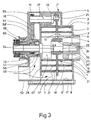
- the displacement machines shown in the drawing have a rotor that acts as a displacer 1. He points on both sides of a disc 2 by at least two spirally arranged approximately 180 ° apart running displacers on by Molded bars 3, 3 'held perpendicular to the disk 2 are. The spirals themselves are in the example shown formed from several adjoining arcs. As a result of the large ratio shown in FIG. 2 is between the axial length and the wall thickness inlet-side end area 3 "of the strips 3, 3 'in each case reinforced. 4 with a hub is designated with which the disc 2 is mounted on a bearing 22. The bearing 22 itself sits on an eccentric disk 23, which in turn is part of a drive shaft 24; the axis of rotation the drive shaft 24 is designated 59.
- 3 ' Eye of the disc 2 designated for receiving a guide bearing 25, which is mounted on an eccentric bolt 26 is. For its part, it is part of a guide shaft 27.
- the eccentricity e of the eccentric disk 23 on the drive shaft 24 corresponds to that of the eccentric bolt 26 the guide shaft 27.
- 3 '2 openings 6 are excluded in the disc, a working medium from one side of the disc can get to the other, for example, through one central outlet 13 of one on the right in FIGS. 2 and 3 Housing half 7 'to be led away.
- a pulley which is rotatably connected to the drive shaft 24 is connected.
- FIG. 2 is a housing half shown on the left in Fig. 1 7 one of the two to each other in the axial direction adjacent housing halves 7 and 7 ', via fastening eyes 8 for receiving screw connections 8 'interconnected machine housing 7 "shown. 11 and 11 'respectively denote two at least approximately Conveyor spaces offset by 180 °, which according to Art a spiral slot in the two halves of the housing 7, 7 'are incorporated. They run from one each at the radially outer end of the spiral slots in the Housing 7 "arranged inlet 12, 12 'to the radially inside lying, two delivery rooms 11, 11 'common outlet 13, which is integrally formed on the housing part 7 '.
- FIG. 2 shows that a web 17 ′ at the inlet 12 with the outer cylinder wall 14 'in a web 18' also continues with the inner cylinder wall 15.
- inlet 12 ' the transition takes place here from a web 17 to a web 18.
- the drive and the leadership of the displacer 1 get the on the housing parts 7, 7 ', drive shaft 24 and the spaced from it, on the housing part 7 parallel axis mounted guide shaft 27.
- a form-fit belt drive 16 for example Timing belt
- 9 symbolizes in Fig. 2 a toothed belt pulley, which on the Drive shaft 24 sits and 10 with respect to the number of teeth same toothed belt pulley for the guide shaft 27.
- This Double eccentric drive for the displacer 1 ensures that all points of the two strips 3, 3 'are circular Execute shifting movement.
- the displacer 1 leads thus a torsion-free circular movement.
- the housing part 7 has an essentially flat end face Side wall 28, which is perpendicular to the axis of rotation 59 runs.
- a graduated front Side wall of the housing part 7 ' is designated 28'.
- the outlet-shaped outlet 13 formed on which a bearing arrangement for this side bearings of the drive shaft 24 is supported.
- FIG. 1 and 3 show that the openings of the two inlets 12, 12 'offset by approximately 180 ° to one another on the side wall 28 of the housing part 7 are arranged.
- This in Inlet openings extending in the axial direction open into a space 51, which by a hood 50 and the housing wall 28 is limited.
- the axial direction on the Housing half 7 attached hood 50 is located on the front and close to the housing wall 28 and in turn has one nozzle-shaped connection projecting in the axial direction 52 on which one upstream of the displacement machine Device, for example one not shown here Air filter, can be connected.
- This arrangement has several advantages: The displacement machine is through this type of connection of the two inlets 12, 12 'not widened in the radial direction.
- hood 50 arises in that it a circular cylindrical, in the axial direction against has protruding projection 53 on the outside, which has a bearing 54 records.
- This bearing carries the pulley 19, which rotatably by means of a radially elastic element 55 the drive shaft 24 is connected.
- This enables the a drive belt, not shown here Radial force are supported on the extension 53; the Drive shaft 24 is only by the drive torque charged.
- a Rolling bearing 58 include, via which the drive shaft 24th is mounted on the side wall 28.
- the hood 50 with respect to the axis of rotation 59 of the drive shaft 24 clearly positioned in the radial direction, so that the axis of rotation of the pulley 19 with the axis of rotation 59 of the drive shaft 24 coincides.
- the hood 50 is by means of the connecting elements 8 'in axial direction with the housing halves 7, 7 'firmly connected.
- pooling inlets 12, 12 'by means of the hood 50 is created by guiding the Working medium past roller bearing 58. This is in the Machine operation heated by the shaft 24. Because now through the hood 50 part of the working medium - e.g. cold intake air - flowing past extensions 56, 56 ', these are cooled and since they have the outer ring 57 of the Rolling bearing 58 include, cool this.
- hood 50 with the extension 53 is in the fact that this instead of the rotationally fixed with the Drive pulley 19 connected to shaft 24, e.g. a Electromagnetic clutch 60, which is well known, but here not described, can record; this is in 3 shown.
- the corresponding pulley 19 ' is as described above, using a roller bearing 54 'of the electromagnetic clutch 60 on the extension 53 supported.
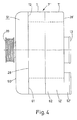
- the housing 7 " also two axially abutting Housing parts 7, 7 '.
- a displacer 1 arranged over the pulley 19 is driven.
- a hood 50 is arranged on the end face together with the side wall 28 of the housing part 7 the space 51 limited.
- This side wall 28 has the opening on the one hand the inlet 12 and on the other hand, this approximately diametrically opposite, a passage 61.
- the Passage 61 is in the housing 7 "above that as a continuous Connection channel 62 formed inlet 12 'connected to the flow, its opening on the front side wall 28 'of the other housing part 7' in the manner of a connecting piece 52 'is integrally formed.
- the connection is 12 thus connected through the space 51 to the inlet 12 '.
- 13 denotes the all, not shown in Fig. 4, conveyor rooms common outlet.
- the funding areas are the same formed as shown in FIGS. 1 to 3 and accordingly with the connecting channel 62 or the inlet 12 connected.
- the peripheral shape of the hood 50 is preferably on adapted the shape of the housing 7 ", as shown in FIG. 2 can be seen. But it is also conceivable that the hood 50 has a different shape, preferably but does not project in the radial direction over the housing 7 ".
- the openings of the inlets 12, 12 ' can be arranged on the casing side of the housing and the Hood has corresponding extensions to these openings to cover.
- the extensions could be the shape of the housing section have, as shown in FIG. 2, the Limit inlets 12, 12 '.
- the hood 50 can without the extensions 53 and / or 56, 56 ' be trained.
Landscapes
- Engineering & Computer Science (AREA)
- Mechanical Engineering (AREA)
- General Engineering & Computer Science (AREA)
- Rotary Pumps (AREA)
- Applications Or Details Of Rotary Compressors (AREA)
- Structures Of Non-Positive Displacement Pumps (AREA)
- Iron Core Of Rotating Electric Machines (AREA)
- Vending Machines For Individual Products (AREA)
- Screw Conveyors (AREA)
Claims (9)
- Machine à refoulement pour fluides compressibles, comprenant un boítier (7") comprenant une paroi latérale (28) du côté frontal, des chambres de refoulement (11, 11') disposées dans le boítier (7"), qui mènent depuis au moins deux entrées radiales extérieures (12, 12') du boítier (7") à une sortie radiale intérieure (13) du boítier (7"), et un organe de refoulement (1) associé aux chambres de refoulement (11, 11'), qui comprend une plaque (2) et des barrettes (3,3') en forme de spirale, disposées perpendiculairement sur cette plaque et pénétrant dans les chambres de refoulement (11, 11'), les barrettes (3,3') entraínées de manière excentrique exécutant avec chacun de leurs points un mouvement circulaire délimité par les parois (14, 14', 15, 15') des chambres de refoulement (11, 11'), caractérisée par un capot (50) posé sur le boítier (7"), qui délimite conjointement avec la paroi latérale (28) une chambre (51) qui relie les entrées (12, 12') l'une à l'autre.
- Machine à refoulement selon la revendication 1, caractérisée en ce que les entrées (12, 12') sont disposées sur la paroi latérale (28), et en ce que le capot (50) comporte un raccord (52).
- Machine à refoulement selon la revendication 1, caractérisée en ce qu'une entrée (12'), et une traversée (61) reliée à l'autre entrée (12) sont disposées sur la paroi latérale (23), et en ce que la chambre (51) relie la traversée (61) avec l'entrée (12') disposée sur la paroi latérale (28).
- Machine à refoulement selon la revendication 3, caractérisée en ce que ladite autre entrée (12) est disposée sur une paroi latérale (28') du boítier (7") opposée à la paroi latérale (28).
- Machine à refoulement selon l'une des revendications 1 à 4, caractérisée en ce que l'organe de refoulement (1) est monté sur un arbre d'entraínement (24) et sur un arbre de guidage (27), lesquels sont montés sur le boítier (7"), et en ce que pour leur synchronisation les deux arbres (24, 27) sont reliés l'un à l'autre dans la chambre (51) délimitée par le capot (50) et par la paroi latérale (28).
- Machine à refoulement selon l'une des revendications 1 à 5, caractérisée en ce que le boítier (7") comprend deux parties de boítier (7, 7') appliquées l'une contre l'autre en direction axiale, et en ce que les parties de boítier (7, 7') et le capot (50) sont retenus ensemble au moyen d'un vissage (8').
- Machine à refoulement selon l'une des revendications 1 à 6, caractérisée en ce que le capot (50) comprend un prolongement intérieur (56) qui dépasse en direction de la paroi latérale (28) et qui entoure une bague extérieure (57) d'un palier (58) logé dans la paroi latérale (28) et agencé au centre, pour l'arbre d'entraínement (24).
- Machine à refoulement selon l'une des revendications 1 à 7, caractérisée en ce que le capot (50) comporte un prolongement extérieur (53), dépassant vers l'extérieur en direction axiale, au moins approximativement de forme cylindrique droite et traversé par l'arbre d'entraínement (24), pour la réception d'un palier (54) sur lequel est montée une poulie d'entraínement (19).
- Machine à refoulement selon la revendication 8, caractérisée en ce qu'un embrayage électro-magnétique (60) est agencé entre la poulie d'entraínement (19) et l'arbre d'entraínement (24).
Applications Claiming Priority (3)
| Application Number | Priority Date | Filing Date | Title |
|---|---|---|---|
| CH1984/97 | 1997-08-26 | ||
| CH198497 | 1997-08-26 | ||
| CH198497 | 1997-08-26 |
Publications (2)
| Publication Number | Publication Date |
|---|---|
| EP0899424A1 EP0899424A1 (fr) | 1999-03-03 |
| EP0899424B1 true EP0899424B1 (fr) | 2001-11-28 |
Family
ID=4223195
Family Applications (1)
| Application Number | Title | Priority Date | Filing Date |
|---|---|---|---|
| EP98115306A Expired - Lifetime EP0899424B1 (fr) | 1997-08-26 | 1998-08-14 | Machine de déplacement de fluide du type à spirale |
Country Status (8)
| Country | Link |
|---|---|
| US (1) | US6132193A (fr) |
| EP (1) | EP0899424B1 (fr) |
| JP (1) | JPH11132185A (fr) |
| CN (1) | CN1210196A (fr) |
| AT (1) | ATE209751T1 (fr) |
| CA (1) | CA2245605A1 (fr) |
| DE (1) | DE59802216D1 (fr) |
| ES (1) | ES2164398T3 (fr) |
Families Citing this family (7)
| Publication number | Priority date | Publication date | Assignee | Title |
|---|---|---|---|---|
| US6364643B1 (en) * | 2000-11-10 | 2002-04-02 | Scroll Technologies | Scroll compressor with dual suction passages which merge into suction path |
| NL1028471C2 (nl) * | 2005-03-07 | 2006-09-11 | Hemodynamics Holding B V | Pomp voor kwetsbaar fluïdum, gebruik van dergelijke pomp voor pompen van bloed. |
| EP2179138B1 (fr) * | 2007-07-26 | 2015-09-09 | Spinnler Engineering | Machine de déplacement de matière fonctionnant selon le principe de la spirale |
| ATE533920T1 (de) * | 2007-08-22 | 2011-12-15 | Spinnler Engineering | Verdrängermaschine nach dem spiralprinzip |
| DE102011103165A1 (de) * | 2010-07-02 | 2012-01-05 | Handtmann Systemtechnik Gmbh & Co. Kg | Ladevorrichtung zur Verdichtung von Ladeluft für einen Verbrennungsmotor |
| CN103291616A (zh) * | 2012-03-02 | 2013-09-11 | 日本株式会社富石 | 涡旋式流体机械 |
| WO2017092795A1 (fr) * | 2015-12-01 | 2017-06-08 | Ateliers Busch S.A. | Pompe a vide avec element filtrant |
Family Cites Families (13)
| Publication number | Priority date | Publication date | Assignee | Title |
|---|---|---|---|---|
| JPS61226585A (ja) * | 1985-03-30 | 1986-10-08 | Toshiba Corp | スクロ−ル型圧縮装置 |
| JPS62199984A (ja) * | 1986-02-28 | 1987-09-03 | Toshiba Corp | スクロ−ル型圧縮装置 |
| CH673874A5 (fr) * | 1987-03-24 | 1990-04-12 | Bbc Brown Boveri & Cie | |
| CH673680A5 (fr) * | 1987-12-21 | 1990-03-30 | Bbc Brown Boveri & Cie | |
| DE58906623D1 (de) * | 1988-08-03 | 1994-02-17 | Aginfor Ag | Verdrängermaschine nach dem Spiralprinzip. |
| US4998864A (en) * | 1989-10-10 | 1991-03-12 | Copeland Corporation | Scroll machine with reverse rotation protection |
| JP2568711B2 (ja) * | 1989-12-29 | 1997-01-08 | 松下電器産業株式会社 | 気体圧縮機 |
| JPH04262085A (ja) * | 1991-01-21 | 1992-09-17 | Mitsubishi Electric Corp | スクロール型圧縮機 |
| DE4203346A1 (de) | 1991-02-18 | 1992-08-20 | Volkswagen Ag | Verdraengermaschine |
| EP0545191B1 (fr) * | 1991-12-05 | 1995-09-13 | AGINFOR AG für industrielle Forschung | Machine de déplacement de fluide de type à spirale |
| DE59206416D1 (de) * | 1991-12-05 | 1996-07-04 | Aginfor Ag | Verdrängermaschine nach dem Spiralprinzip |
| EP0547470B1 (fr) * | 1991-12-16 | 1995-08-23 | AGINFOR AG für industrielle Forschung | Machine à déplacement positif selon le principle de la spirale |
| DE4205541A1 (de) * | 1992-02-24 | 1993-08-26 | Asea Brown Boveri | Verdraengermaschine nach dem spiralprinzip |
-
1998
- 1998-08-14 ES ES98115306T patent/ES2164398T3/es not_active Expired - Lifetime
- 1998-08-14 AT AT98115306T patent/ATE209751T1/de not_active IP Right Cessation
- 1998-08-14 EP EP98115306A patent/EP0899424B1/fr not_active Expired - Lifetime
- 1998-08-14 DE DE59802216T patent/DE59802216D1/de not_active Expired - Fee Related
- 1998-08-21 JP JP10235459A patent/JPH11132185A/ja active Pending
- 1998-08-25 CA CA002245605A patent/CA2245605A1/fr not_active Abandoned
- 1998-08-26 US US09/140,676 patent/US6132193A/en not_active Expired - Fee Related
- 1998-08-26 CN CN98120263.2A patent/CN1210196A/zh active Pending
Also Published As
| Publication number | Publication date |
|---|---|
| EP0899424A1 (fr) | 1999-03-03 |
| DE59802216D1 (de) | 2002-01-10 |
| ES2164398T3 (es) | 2002-02-16 |
| US6132193A (en) | 2000-10-17 |
| CN1210196A (zh) | 1999-03-10 |
| ATE209751T1 (de) | 2001-12-15 |
| CA2245605A1 (fr) | 1999-02-26 |
| JPH11132185A (ja) | 1999-05-18 |
Similar Documents
| Publication | Publication Date | Title |
|---|---|---|
| EP0354342B1 (fr) | Machine de déplacement de fluide de type à spirale | |
| EP0371305B1 (fr) | Arbre excentré à contrepoids | |
| DE3542776C2 (fr) | ||
| EP0899423B1 (fr) | Machine de déplacement de fluide du type à spirale | |
| EP0284774B1 (fr) | Machine à déplacement du type à spirale | |
| EP0899424B1 (fr) | Machine de déplacement de fluide du type à spirale | |
| EP0321781B1 (fr) | Machine de déplacement de fluide du type à spirale | |
| EP0614012A1 (fr) | Machine de déplacement de fluide du type à spirales | |
| DE102005052623B4 (de) | Kompressor | |
| EP0201774B1 (fr) | Machine à piston rotatif à déplacement positif | |
| EP0547470B1 (fr) | Machine à déplacement positif selon le principle de la spirale | |
| EP0351690A1 (fr) | Compresseur rotatif à spirales pour fluides compressibles | |
| EP0545190A1 (fr) | Machine de déplacement de fluide de type à spirale | |
| EP0561212B1 (fr) | Machine de déplacement de fluide du type à spirale | |
| EP0560009A1 (fr) | Machine à déplacement positif selon le principe de la spirale | |
| EP0597804B1 (fr) | Machine de déplacement de fluide du type à spirale' | |
| EP0545187B1 (fr) | Machine de déplacement de fluide de type à spirale | |
| EP0545191A1 (fr) | Machine de déplacement de fluide de type à spirale | |
| WO1999022118A1 (fr) | Dispositif pour le transport d'un milieu ou pour l'entrainement a travers un milieu | |
| DE3525933A1 (de) | Spiralverdichter | |
| EP2195511B1 (fr) | Machine de refoulement à spirales | |
| EP0545188B1 (fr) | Machine de déplacement de fluide de type à spirale | |
| DE3839252A1 (de) | Verdraengermaschine nach dem spiralprinzip | |
| DE3814931A1 (de) | Maschinenanordnung | |
| DE10023010C2 (de) | Innenachsige Mehrfachdrehkolbenmaschine |
Legal Events
| Date | Code | Title | Description |
|---|---|---|---|
| PUAI | Public reference made under article 153(3) epc to a published international application that has entered the european phase |
Free format text: ORIGINAL CODE: 0009012 |
|
| AK | Designated contracting states |
Kind code of ref document: A1 Designated state(s): AT BE CH DE ES FR GB IE IT LI NL SE |
|
| AX | Request for extension of the european patent |
Free format text: AL;LT;LV;MK;RO;SI |
|
| 17P | Request for examination filed |
Effective date: 19990820 |
|
| AKX | Designation fees paid |
Free format text: AT BE CH DE ES FR GB IE IT LI NL SE |
|
| RAP1 | Party data changed (applicant data changed or rights of an application transferred) |
Owner name: CRT COMMON RAIL TECHNOLOGIES AG |
|
| GRAG | Despatch of communication of intention to grant |
Free format text: ORIGINAL CODE: EPIDOS AGRA |
|
| GRAG | Despatch of communication of intention to grant |
Free format text: ORIGINAL CODE: EPIDOS AGRA |
|
| GRAH | Despatch of communication of intention to grant a patent |
Free format text: ORIGINAL CODE: EPIDOS IGRA |
|
| 17Q | First examination report despatched |
Effective date: 20010409 |
|
| GRAH | Despatch of communication of intention to grant a patent |
Free format text: ORIGINAL CODE: EPIDOS IGRA |
|
| GRAA | (expected) grant |
Free format text: ORIGINAL CODE: 0009210 |
|
| AK | Designated contracting states |
Kind code of ref document: B1 Designated state(s): AT BE CH DE ES FR GB IE IT LI NL SE |
|
| PG25 | Lapsed in a contracting state [announced via postgrant information from national office to epo] |
Ref country code: NL Free format text: LAPSE BECAUSE OF FAILURE TO SUBMIT A TRANSLATION OF THE DESCRIPTION OR TO PAY THE FEE WITHIN THE PRESCRIBED TIME-LIMIT Effective date: 20011128 Ref country code: IE Free format text: LAPSE BECAUSE OF FAILURE TO SUBMIT A TRANSLATION OF THE DESCRIPTION OR TO PAY THE FEE WITHIN THE PRESCRIBED TIME-LIMIT Effective date: 20011128 |
|
| REF | Corresponds to: |
Ref document number: 209751 Country of ref document: AT Date of ref document: 20011215 Kind code of ref document: T |
|
| REG | Reference to a national code |
Ref country code: CH Ref legal event code: EP |
|
| REG | Reference to a national code |
Ref country code: IE Ref legal event code: FG4D Free format text: GERMAN |
|
| REG | Reference to a national code |
Ref country code: GB Ref legal event code: IF02 |
|
| REF | Corresponds to: |
Ref document number: 59802216 Country of ref document: DE Date of ref document: 20020110 |
|
| REG | Reference to a national code |
Ref country code: ES Ref legal event code: FG2A Ref document number: 2164398 Country of ref document: ES Kind code of ref document: T3 |
|
| PG25 | Lapsed in a contracting state [announced via postgrant information from national office to epo] |
Ref country code: SE Free format text: LAPSE BECAUSE OF FAILURE TO SUBMIT A TRANSLATION OF THE DESCRIPTION OR TO PAY THE FEE WITHIN THE PRESCRIBED TIME-LIMIT Effective date: 20020228 |
|
| GBT | Gb: translation of ep patent filed (gb section 77(6)(a)/1977) |
Effective date: 20020207 |
|
| ET | Fr: translation filed | ||
| NLV1 | Nl: lapsed or annulled due to failure to fulfill the requirements of art. 29p and 29m of the patents act | ||
| REG | Reference to a national code |
Ref country code: IE Ref legal event code: FD4D |
|
| PG25 | Lapsed in a contracting state [announced via postgrant information from national office to epo] |
Ref country code: GB Free format text: LAPSE BECAUSE OF NON-PAYMENT OF DUE FEES Effective date: 20020814 Ref country code: AT Free format text: LAPSE BECAUSE OF NON-PAYMENT OF DUE FEES Effective date: 20020814 |
|
| PG25 | Lapsed in a contracting state [announced via postgrant information from national office to epo] |
Ref country code: ES Free format text: LAPSE BECAUSE OF NON-PAYMENT OF DUE FEES Effective date: 20020815 |
|
| PG25 | Lapsed in a contracting state [announced via postgrant information from national office to epo] |
Ref country code: BE Free format text: LAPSE BECAUSE OF NON-PAYMENT OF DUE FEES Effective date: 20020831 |
|
| PLBE | No opposition filed within time limit |
Free format text: ORIGINAL CODE: 0009261 |
|
| STAA | Information on the status of an ep patent application or granted ep patent |
Free format text: STATUS: NO OPPOSITION FILED WITHIN TIME LIMIT |
|
| 26N | No opposition filed | ||
| PGFP | Annual fee paid to national office [announced via postgrant information from national office to epo] |
Ref country code: CH Payment date: 20030131 Year of fee payment: 5 |
|
| BERE | Be: lapsed |
Owner name: COMMON RAIL TECHNOLOGIES A.G. *CRT Effective date: 20020831 |
|
| PG25 | Lapsed in a contracting state [announced via postgrant information from national office to epo] |
Ref country code: DE Free format text: LAPSE BECAUSE OF NON-PAYMENT OF DUE FEES Effective date: 20030301 |
|
| GBPC | Gb: european patent ceased through non-payment of renewal fee |
Effective date: 20020814 |
|
| PG25 | Lapsed in a contracting state [announced via postgrant information from national office to epo] |
Ref country code: FR Free format text: LAPSE BECAUSE OF NON-PAYMENT OF DUE FEES Effective date: 20030430 |
|
| REG | Reference to a national code |
Ref country code: FR Ref legal event code: ST |
|
| PG25 | Lapsed in a contracting state [announced via postgrant information from national office to epo] |
Ref country code: LI Free format text: LAPSE BECAUSE OF NON-PAYMENT OF DUE FEES Effective date: 20030831 Ref country code: CH Free format text: LAPSE BECAUSE OF NON-PAYMENT OF DUE FEES Effective date: 20030831 |
|
| REG | Reference to a national code |
Ref country code: CH Ref legal event code: PL |
|
| REG | Reference to a national code |
Ref country code: ES Ref legal event code: FD2A Effective date: 20030912 |
|
| PG25 | Lapsed in a contracting state [announced via postgrant information from national office to epo] |
Ref country code: IT Free format text: LAPSE BECAUSE OF NON-PAYMENT OF DUE FEES Effective date: 20050814 |