EP0899423B1 - Machine de déplacement de fluide du type à spirale - Google Patents
Machine de déplacement de fluide du type à spirale Download PDFInfo
- Publication number
- EP0899423B1 EP0899423B1 EP98115305A EP98115305A EP0899423B1 EP 0899423 B1 EP0899423 B1 EP 0899423B1 EP 98115305 A EP98115305 A EP 98115305A EP 98115305 A EP98115305 A EP 98115305A EP 0899423 B1 EP0899423 B1 EP 0899423B1
- Authority
- EP
- European Patent Office
- Prior art keywords
- bars
- displacement machine
- inner sealing
- displacer
- approximately
- Prior art date
- Legal status (The legal status is an assumption and is not a legal conclusion. Google has not performed a legal analysis and makes no representation as to the accuracy of the status listed.)
- Expired - Lifetime
Links
Images


Classifications
-
- F—MECHANICAL ENGINEERING; LIGHTING; HEATING; WEAPONS; BLASTING
- F04—POSITIVE - DISPLACEMENT MACHINES FOR LIQUIDS; PUMPS FOR LIQUIDS OR ELASTIC FLUIDS
- F04C—ROTARY-PISTON, OR OSCILLATING-PISTON, POSITIVE-DISPLACEMENT MACHINES FOR LIQUIDS; ROTARY-PISTON, OR OSCILLATING-PISTON, POSITIVE-DISPLACEMENT PUMPS
- F04C29/00—Component parts, details or accessories of pumps or pumping installations, not provided for in groups F04C18/00 - F04C28/00
- F04C29/0021—Systems for the equilibration of forces acting on the pump
- F04C29/0035—Equalization of pressure pulses
-
- F—MECHANICAL ENGINEERING; LIGHTING; HEATING; WEAPONS; BLASTING
- F01—MACHINES OR ENGINES IN GENERAL; ENGINE PLANTS IN GENERAL; STEAM ENGINES
- F01C—ROTARY-PISTON OR OSCILLATING-PISTON MACHINES OR ENGINES
- F01C1/00—Rotary-piston machines or engines
- F01C1/02—Rotary-piston machines or engines of arcuate-engagement type, i.e. with circular translatory movement of co-operating members, each member having the same number of teeth or tooth-equivalents
- F01C1/0207—Rotary-piston machines or engines of arcuate-engagement type, i.e. with circular translatory movement of co-operating members, each member having the same number of teeth or tooth-equivalents both members having co-operating elements in spiral form
- F01C1/0215—Rotary-piston machines or engines of arcuate-engagement type, i.e. with circular translatory movement of co-operating members, each member having the same number of teeth or tooth-equivalents both members having co-operating elements in spiral form where only one member is moving
- F01C1/0223—Rotary-piston machines or engines of arcuate-engagement type, i.e. with circular translatory movement of co-operating members, each member having the same number of teeth or tooth-equivalents both members having co-operating elements in spiral form where only one member is moving with symmetrical double wraps
-
- F—MECHANICAL ENGINEERING; LIGHTING; HEATING; WEAPONS; BLASTING
- F01—MACHINES OR ENGINES IN GENERAL; ENGINE PLANTS IN GENERAL; STEAM ENGINES
- F01C—ROTARY-PISTON OR OSCILLATING-PISTON MACHINES OR ENGINES
- F01C1/00—Rotary-piston machines or engines
- F01C1/02—Rotary-piston machines or engines of arcuate-engagement type, i.e. with circular translatory movement of co-operating members, each member having the same number of teeth or tooth-equivalents
- F01C1/0207—Rotary-piston machines or engines of arcuate-engagement type, i.e. with circular translatory movement of co-operating members, each member having the same number of teeth or tooth-equivalents both members having co-operating elements in spiral form
- F01C1/0246—Details concerning the involute wraps or their base, e.g. geometry
Definitions
- the present invention relates to a displacement machine for compressible media according to the preamble of the claim 1.
- a generic displacement machine based on the spiral principle is known for example from DE-A-42 03 346.
- Machines of this type are characterized by pulsations of relatively low amplitude promotion of for example from air or an air-fuel mixture existing gaseous working medium and can therefore also for charging internal combustion engines Advantage.
- a positive displacement machine along spiral conveying spaces between also spirally formed, acting as a displacer Strips and the two cylinder walls of the delivery rooms due to different curvature of the spiral shape, about crescent-shaped work chambers included, which themselves from an inlet for the work equipment through the Move delivery rooms through to an outlet, whereby their volume is constantly decreasing and the pressure of the Working medium is increased accordingly.
- each ledge has outer faces when viewed in the radial direction and inner sealing surfaces, which at the beginning on the inlet side of the strips start and at the outlet end the last end.
- Each of the strips thus forms together with the corresponding cylinder wall of the assigned delivery chamber a working chamber every 180 ° angle of rotation of the drive.
- CH Patent Specification No. 673 679 also shows in detail the way, as in displacement machines after the Spiral principle the working chambers by a circular movement the one attached to the disc of the displacer Last in cooperation with the spiral conveyor rooms arise in the housing.
- Such work chambers will be both through the inside of the bar and through the Outside limited.
- Typical of this arrangement is that from a spiral ledge as it progresses Rotary movement of the eccentric drive and guide shafts a new working chamber every 180 ° is formed, or the filling process of a working chamber is completed.
- DE-A-41 33 429 discloses a possibility of symmetrical Disrupt sequence of suction and delivery cycles.
- the solution shown therein assumes that the funding areas in the Housing and the spiral strips on the disc of the To shift the rotor polarly so that the Sequence of suction and delivery cycles no longer uniform is. Furthermore, the strips are on the pane the runner no longer mirror-symmetrical on both sides arranged the disc, but again angular with respect the axis of rotation of the eccentric drive shaft against each other postponed. This creates the desired irregularity the suction and delivery cycles of the machine elevated.
- the displacement machine according to the invention has given Speed of the drive an increased periodicity of Suction and delivery cycles. Show any pulsations therefore only very small amplitudes.
- the present invention leaves a completely symmetrical one Arrangement of the strips on the pane too what helps the pulsations as well as tilting moments on the Prevent or reduce displacers.
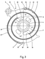
- the bearing 22 itself sits on an eccentric disk 23, which in turn is part of a drive shaft 24 is.
- a radially outside of the strips 3, 3 ' is arranged Eye of the disc 2, which is a guide bearing 25 picks up, which on an eccentric bolt 26 is raised.
- the eccentricity e (Fig. 2) of the eccentric 23 on the drive shaft 24 corresponds to that of the eccentric bolt 26 the guide shaft 27.
- Are the outlet side of the strips 3, 3 ' 2 openings 6 are present in the disk, so that the working medium get from one side of the disc to the other can, for example, through a central outlet 13 to be led away, the one on the right in Fig. 1 shown housing part 7 'of the housing 7 "is formed.
- a pulley is designated, which is rotatably with the drive shaft 24 is connected.
- the drive shaft 24 is in one by means of a bearing 58 1 on the left in FIG. 1 and by means of of a bearing 62 in the housing part 7 '.
- Guide shaft 27 is also fixed against rotation Toothed belt pulley 10 which by means of a toothed belt 16 for angularly accurate synchronous drive of the guide shaft 27 with the drive shaft 24 coupled to the toothed belt pulley 9 is.
- Toothed belt pulley 10 which by means of a toothed belt 16 for angularly accurate synchronous drive of the guide shaft 27 with the drive shaft 24 coupled to the toothed belt pulley 9 is.
- Through the drive designed in this way leads the displacer 1 a rotating, rotation-free in machine operation Sliding movement off.
- 40, 40 ' are centrifugal weights, which are attached to the drive shaft 24. They serve to compensate for the displacer 1 during Machine operation acting on the eccentric 23 Centrifugal force.
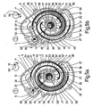
- FIG. 2 is the housing part shown on the left in Fig. 1 7 'of the two axially abutting housing parts 7, 7 'assembled, via mounting eyes 8 for receiving of screw connections 8 'interconnected housing 7 '' shown.
- 11 and 11 ' respectively denote two Conveyor spaces offset by 180 °, which according to Art a spiral slot in each of the two housing parts 7, 7 'are incorporated. They always run one on the radially outer circumference of the spiral in the housing 7 " arranged inlet 12, 12 'to the centrally arranged, two delivery rooms 11, 11 'common outlet 13.
- the displacer 1 is better known Design shown separately.
- they are radial outer and radially inner sealing surfaces 30, 30 'or 31, 31 'forming sections of the strips 3, 3', which on the outer cylinder walls 14, 14 'and inner Cylinder walls 15, 15 'of the machined into the housing parts 7, 7' Funding rooms 11, 11 'for formation and displacement approach the working chambers, entered in bold.
- the inlet side Beginning 32, 33 and the outlet end 34, 35 of the inner sealing surfaces 31, 31 'and outer sealing surfaces 30, 30 ' in the direction of movement of the medium and thus viewed in the circumferential direction, for example opposite.
- the Crosspieces 17, 17 'towards beads protruding inwards 36, which are intended to begin with 32 of the concerned to cooperate with the outer sealing surface 30 or 30 '.
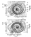
- FIGS. 5a to 5d Shift of beginnings 32, 33 and ends 34, 35 of the sealing surfaces 30, 30 ', 31, 31' on the strips 3, 3 '.
- it is displacer 1 analogous to Fig. 2 inside the housing part 7 ' shown.
- FIG. 5a shows the displacer 1 in a first position, in the outer spiral sealing surface 30 of the strip 3 a first working chamber 41, which is indicated by hatching is included.
- the angle of rotation of the drive is next to the housing 7 '' based on the position of the center of rotation 59 of the drive shaft 24 and the center axis 61 of the eccentric disk 23 shown.
- FIG. 5b shows the displacer 1 in a second position which is the drive with respect to that shown in Fig. 5a Position rotated clockwise by approximately 90 ° Has.
- the working chamber 41 is in this position open on the outlet side and the inner spiral sealing surface 31 the bar 3 closes a second working chamber 42, the also hatched is a.
- This Working chamber 42 has at least approximately the same Size as the working chamber 41.
- FIGS. 5c and 5d show the outside Sealing surface 30 'or inner sealing surface 31' included Working chamber 43 and 44, the further rotation of the drive by about 90 ° angle of rotation be formed.
- FIGS. 5a to 5d it can thus be seen that according to the invention on each side of the disc 2 of the rotor 1 at intervals of approximately 90 ° angle of rotation of the drive in each case a working chamber 41, 42, 43, 44 included becomes.
- the strips 3, 3 ' are opposite the disc 2 of the Displacer 1 arranged symmetrically and the beginnings 32, 33 and ends 34, 35 of the sealing surfaces 30, 30 ', 31, 31' so that the machine operation per revolution of the The resulting working chambers are about the same size are.
Landscapes
- Engineering & Computer Science (AREA)
- Mechanical Engineering (AREA)
- General Engineering & Computer Science (AREA)
- Physics & Mathematics (AREA)
- Geometry (AREA)
- Rotary Pumps (AREA)
- Screw Conveyors (AREA)
- Structures Of Non-Positive Displacement Pumps (AREA)
- Iron Core Of Rotating Electric Machines (AREA)
- Vending Machines For Individual Products (AREA)
Claims (6)
- Machine de déplacement de fluides compressibles avec au moins deux chambres de transport (11, 11') disposées dans une enceinte (7"), qui mènent en forme de spirale d'une entrée (12, 12') située radialement à l'extérieur à une sortie (13) située radialement à l'intérieur, et un corps de déplacement (1) avec un disque (2), accomplissant en service un mouvement circulaire sans rotation, et des volutes (3, 3') en forme de spirales disposées sur un côté du disque (2), qui, vues en direction radiale, présentent des faces d'étanchéité extérieures et intérieures coopérant avec des parois cylindriques extérieures et intérieures (14, 14', 15, 15') des chambres de transport (11, 11'), afin de former en service des chambres de travail (41, 42, 43, 44) déplacées de l'entrée (12, 12') vers la sortie (13), caractérisée en ce que les faces d'étanchéité extérieures et intérieures (30, 30', 31, 31') des volutes (3, 3'), vues dans le sens périphérique, sont décalées afin de former chacune une chambre de travail (41, 42, 43, 44) à une distance angulaire uniforme du mouvement du corps de déplacement (1).
- Machine de déplacement suivant la revendication 1, caractérisée en ce que les faces d'étanchéité extérieures et intérieures (30, 30', 31, 31') présentent du côté de l'entrée des débuts (32, 33) qui sont disposés sur les volutes (3, 3') de telle manière que chaque chambre de travail (41, 42, 43, 44) soit fermée au moins approximativement à une distance angulaire de 90°.
- Machine de déplacement suivant la revendication 1 ou 2, caractérisée en ce que les faces d'étanchéité extérieures et intérieures (30, 30', 31, 31') présentent du côté de la sortie des extrémités (34, 35) qui sont disposées sur les volutes (3, 3') de telle manière que chaque chambre de travail (41, 42, 43, 44) soit ouverte au moins approximativement à une distance angulaire de 90°.
- Machine de déplacement suivant l'une quelconque des revendications 1 à 3, caractérisée en ce que deux volutes (3, 3') sont disposées sur un côté du disque (2) avec un décalage de 180° et que, sur chaque volute (3, 3'), la face d'étanchéité extérieure (30, 30') est disposée avec un décalage correspondant au moins approximativement à une distance angulaire de 90° par rapport à la face d'étanchéité intérieure (31, 31').
- Machine de déplacement suivant l'une quelconque des revendications 1 à 4, caractérisée en ce que les débuts du côté de l'entrée (32, 33) et les extrémités du côté de la sortie (34, 35) des faces d'étanchéité extérieures et intérieures (30, 30', 31, 31') sont disposés sur les volutes (3, 3') de telle manière que les chambres de travail (41, 42, 43, 44) soient au moins approximativement de même grandeur lors de la fermeture et au moins approximativement de la même grandeur lors de l'ouverture.
- Machine de déplacement suivant l'une quelconque des revendications 1 à 5, caractérisée en ce que des volutes (3, 3') coopérant avec des chambres de transport associées (11, 11') sont disposées sur les deux côtés du disque (2), en position symétrique de réflexion par rapport à celui-ci.
Applications Claiming Priority (3)
| Application Number | Priority Date | Filing Date | Title |
|---|---|---|---|
| CH198397 | 1997-08-26 | ||
| CH1983/97 | 1997-08-26 | ||
| CH198397 | 1997-08-26 |
Publications (2)
| Publication Number | Publication Date |
|---|---|
| EP0899423A1 EP0899423A1 (fr) | 1999-03-03 |
| EP0899423B1 true EP0899423B1 (fr) | 2002-12-11 |
Family
ID=4223171
Family Applications (1)
| Application Number | Title | Priority Date | Filing Date |
|---|---|---|---|
| EP98115305A Expired - Lifetime EP0899423B1 (fr) | 1997-08-26 | 1998-08-14 | Machine de déplacement de fluide du type à spirale |
Country Status (7)
| Country | Link |
|---|---|
| US (1) | US6116875A (fr) |
| EP (1) | EP0899423B1 (fr) |
| JP (1) | JPH11132162A (fr) |
| CN (1) | CN1210936A (fr) |
| AT (1) | ATE229612T1 (fr) |
| CA (1) | CA2245629A1 (fr) |
| DE (1) | DE59806600D1 (fr) |
Families Citing this family (16)
| Publication number | Priority date | Publication date | Assignee | Title |
|---|---|---|---|---|
| US20040148951A1 (en) * | 2003-01-24 | 2004-08-05 | Bristol Compressors, Inc, | System and method for stepped capacity modulation in a refrigeration system |
| GB0319513D0 (en) * | 2003-08-19 | 2003-09-17 | Boc Group Plc | Scroll compressor and scroll wall arrangement therefor |
| ATE533920T1 (de) * | 2007-08-22 | 2011-12-15 | Spinnler Engineering | Verdrängermaschine nach dem spiralprinzip |
| EP2280148B1 (fr) * | 2008-04-07 | 2018-09-12 | Mitsubishi Electric Corporation | Machine à fluide à volutes |
| DE202008006927U1 (de) | 2008-05-21 | 2008-07-31 | Handtmann Systemtechnik Gmbh & Co. Kg | Rippengestaltung bei einem Lader nach dem Spiralprinzip |
| DE202008006926U1 (de) | 2008-05-21 | 2008-07-31 | Handtmann Systemtechnik Gmbh & Co. Kg | Schwingenlagerung bei einem Lader nach dem Spiralprinzip |
| DE102010025986A1 (de) | 2010-07-02 | 2012-01-05 | Handtmann Systemtechnik Gmbh & Co. Kg | Ladevorrichtung zur Verdichtung von Ladeluft |
| DE102010025988A1 (de) | 2010-07-02 | 2012-01-26 | Handtmann Systemtechnik Gmbh & Co. Kg | Ladevorrichtung zur Verdichtung von Ladeluft |
| DE102010025985B4 (de) | 2010-07-02 | 2017-11-02 | Handtmann Systemtechnik Gmbh & Co. Kg | Ladevorrichtung zur Verdichtung von Ladeluft |
| DE102011103165A1 (de) | 2010-07-02 | 2012-01-05 | Handtmann Systemtechnik Gmbh & Co. Kg | Ladevorrichtung zur Verdichtung von Ladeluft für einen Verbrennungsmotor |
| DE102012019040B4 (de) | 2012-09-28 | 2014-08-14 | Harald Teinzer | Scrollmotor |
| CN103511293B (zh) * | 2013-10-14 | 2016-05-18 | 黄少平 | 一种空气动力增能器 |
| FR3027633B1 (fr) * | 2014-10-27 | 2016-12-09 | Danfoss Commercial Compressors | Compresseur a spirales |
| EP3056662B1 (fr) | 2015-02-11 | 2018-12-12 | Danfoss A/S | Machine à cellules à ailettes |
| DE102015220130B4 (de) * | 2015-10-15 | 2020-01-30 | Handtmann Systemtechnik Gmbh & Co. Kg | Verdichtereinrichtung für einen Verbrennungsmotor, Antriebsvorrichtung, Kraftfahrzeug |
| DE102023126031A1 (de) * | 2023-09-26 | 2025-03-27 | Zf Cv Systems Global Gmbh | Scrollverdichter-Anordnung |
Family Cites Families (13)
| Publication number | Priority date | Publication date | Assignee | Title |
|---|---|---|---|---|
| CH586348A5 (fr) * | 1975-02-07 | 1977-03-31 | Aginfor Ag | |
| JPS60104788A (ja) * | 1983-11-14 | 1985-06-10 | Sanden Corp | スクロ−ル型圧縮機 |
| CH667497A5 (de) * | 1985-04-26 | 1988-10-14 | Bbc Brown Boveri & Cie | Rotationskolben-verdraengungsarbeitsmaschine. |
| CH673874A5 (fr) * | 1987-03-24 | 1990-04-12 | Bbc Brown Boveri & Cie | |
| CH673680A5 (fr) * | 1987-12-21 | 1990-03-30 | Bbc Brown Boveri & Cie | |
| CH673679A5 (fr) * | 1987-12-21 | 1990-03-30 | Bbc Brown Boveri & Cie | |
| US5171140A (en) * | 1990-10-19 | 1992-12-15 | Volkswagen Ag | Spiral displacement machine with angularly offset spiral vanes |
| DE4133428C2 (de) * | 1990-10-19 | 2002-12-12 | Volkswagen Ag | Spiralverdrängermaschine |
| DE4133429A1 (de) * | 1990-10-19 | 1992-04-23 | Volkswagen Ag | Spiralverdraengermaschine |
| DE4203346A1 (de) | 1991-02-18 | 1992-08-20 | Volkswagen Ag | Verdraengermaschine |
| JPH0579462A (ja) * | 1991-04-10 | 1993-03-30 | Mitsuba Electric Mfg Co Ltd | スクロールポンプ |
| JPH07503051A (ja) * | 1992-01-27 | 1995-03-30 | フオード モーター カンパニー | スクロールコンプレッサ |
| JPH0979151A (ja) * | 1995-09-11 | 1997-03-25 | Sanyo Electric Co Ltd | スクロール圧縮機 |
-
1998
- 1998-08-14 EP EP98115305A patent/EP0899423B1/fr not_active Expired - Lifetime
- 1998-08-14 DE DE59806600T patent/DE59806600D1/de not_active Expired - Fee Related
- 1998-08-14 AT AT98115305T patent/ATE229612T1/de not_active IP Right Cessation
- 1998-08-20 JP JP10234061A patent/JPH11132162A/ja active Pending
- 1998-08-25 CA CA002245629A patent/CA2245629A1/fr not_active Abandoned
- 1998-08-26 CN CN98120353A patent/CN1210936A/zh active Pending
- 1998-08-26 US US09/140,675 patent/US6116875A/en not_active Expired - Fee Related
Also Published As
| Publication number | Publication date |
|---|---|
| CN1210936A (zh) | 1999-03-17 |
| EP0899423A1 (fr) | 1999-03-03 |
| ATE229612T1 (de) | 2002-12-15 |
| US6116875A (en) | 2000-09-12 |
| JPH11132162A (ja) | 1999-05-18 |
| DE59806600D1 (de) | 2003-01-23 |
| CA2245629A1 (fr) | 1999-02-26 |
Similar Documents
| Publication | Publication Date | Title |
|---|---|---|
| EP0899423B1 (fr) | Machine de déplacement de fluide du type à spirale | |
| DE4241320C2 (de) | Drehkolbenmaschine | |
| EP0354342B1 (fr) | Machine de déplacement de fluide de type à spirale | |
| EP0392975B1 (fr) | Suralimentateur rotatif à spirales pour milieux compressibles | |
| EP0371305B1 (fr) | Arbre excentré à contrepoids | |
| EP0614012B1 (fr) | Machine de déplacement de fluide du type à spirales | |
| EP0321781B1 (fr) | Machine de déplacement de fluide du type à spirale | |
| EP0284774A1 (fr) | Machine à déplacement du type à spirale | |
| EP0547470B1 (fr) | Machine à déplacement positif selon le principle de la spirale | |
| DE1653921B2 (de) | Rotationskolbenpumpe | |
| EP0545190B1 (fr) | Machine de déplacement de fluide de type à spirale | |
| DE2313587A1 (de) | Rotationskompressor | |
| EP1005604B1 (fr) | Machine a piston rotatif | |
| EP0899424A1 (fr) | Machine de déplacement de fluide du type à spirale | |
| EP0560009A1 (fr) | Machine à déplacement positif selon le principe de la spirale | |
| DE2533776A1 (de) | Drehmotor | |
| DE3525933C2 (fr) | ||
| EP0545191B1 (fr) | Machine de déplacement de fluide de type à spirale | |
| DE3404222C2 (fr) | ||
| DE3727281A1 (de) | Rotationskolbenkompressor | |
| DE2229532C3 (de) | Drehkolbenmaschine | |
| EP0841484A1 (fr) | Pompe rotative | |
| EP0597804A1 (fr) | Machine de déplacement de fluide du type à spirale' | |
| WO1997013957A1 (fr) | Moteur a piston rotatif | |
| EP0545188B1 (fr) | Machine de déplacement de fluide de type à spirale |
Legal Events
| Date | Code | Title | Description |
|---|---|---|---|
| PUAI | Public reference made under article 153(3) epc to a published international application that has entered the european phase |
Free format text: ORIGINAL CODE: 0009012 |
|
| AK | Designated contracting states |
Kind code of ref document: A1 Designated state(s): AT BE CH DE ES FR GB IE IT LI NL SE |
|
| AX | Request for extension of the european patent |
Free format text: AL;LT;LV;MK;RO;SI |
|
| 17P | Request for examination filed |
Effective date: 19990820 |
|
| AKX | Designation fees paid |
Free format text: AT BE CH DE ES FR GB IE IT LI NL SE |
|
| RAP1 | Party data changed (applicant data changed or rights of an application transferred) |
Owner name: CRT COMMON RAIL TECHNOLOGIES AG |
|
| GRAG | Despatch of communication of intention to grant |
Free format text: ORIGINAL CODE: EPIDOS AGRA |
|
| 17Q | First examination report despatched |
Effective date: 20020429 |
|
| GRAG | Despatch of communication of intention to grant |
Free format text: ORIGINAL CODE: EPIDOS AGRA |
|
| GRAH | Despatch of communication of intention to grant a patent |
Free format text: ORIGINAL CODE: EPIDOS IGRA |
|
| GRAH | Despatch of communication of intention to grant a patent |
Free format text: ORIGINAL CODE: EPIDOS IGRA |
|
| GRAA | (expected) grant |
Free format text: ORIGINAL CODE: 0009210 |
|
| AK | Designated contracting states |
Kind code of ref document: B1 Designated state(s): AT BE CH DE ES FR GB IE IT LI NL SE |
|
| PG25 | Lapsed in a contracting state [announced via postgrant information from national office to epo] |
Ref country code: NL Free format text: LAPSE BECAUSE OF FAILURE TO SUBMIT A TRANSLATION OF THE DESCRIPTION OR TO PAY THE FEE WITHIN THE PRESCRIBED TIME-LIMIT Effective date: 20021211 Ref country code: IT Free format text: LAPSE BECAUSE OF FAILURE TO SUBMIT A TRANSLATION OF THE DESCRIPTION OR TO PAY THE FEE WITHIN THE PRE;WARNING: LAPSES OF ITALIAN PATENTS WITH EFFECTIVE DATE BEFORE 2007 MAY HAVE OCCURRED AT ANY TIME BEFORE 2007. THE CORRECT EFFECTIVE DATE MAY BE DIFFERENT FROM THE ONE RECORDED.SCRIBED TIME-LIMIT Effective date: 20021211 Ref country code: IE Free format text: LAPSE BECAUSE OF FAILURE TO SUBMIT A TRANSLATION OF THE DESCRIPTION OR TO PAY THE FEE WITHIN THE PRESCRIBED TIME-LIMIT Effective date: 20021211 Ref country code: GB Free format text: LAPSE BECAUSE OF FAILURE TO SUBMIT A TRANSLATION OF THE DESCRIPTION OR TO PAY THE FEE WITHIN THE PRESCRIBED TIME-LIMIT Effective date: 20021211 Ref country code: FR Free format text: LAPSE BECAUSE OF NON-PAYMENT OF DUE FEES Effective date: 20021211 |
|
| REF | Corresponds to: |
Ref document number: 229612 Country of ref document: AT Date of ref document: 20021215 Kind code of ref document: T |
|
| REG | Reference to a national code |
Ref country code: GB Ref legal event code: FG4D Free format text: NOT ENGLISH |
|
| REG | Reference to a national code |
Ref country code: CH Ref legal event code: EP |
|
| REG | Reference to a national code |
Ref country code: IE Ref legal event code: FG4D Free format text: GERMAN |
|
| REF | Corresponds to: |
Ref document number: 59806600 Country of ref document: DE Date of ref document: 20030123 |
|
| PG25 | Lapsed in a contracting state [announced via postgrant information from national office to epo] |
Ref country code: SE Free format text: LAPSE BECAUSE OF FAILURE TO SUBMIT A TRANSLATION OF THE DESCRIPTION OR TO PAY THE FEE WITHIN THE PRESCRIBED TIME-LIMIT Effective date: 20030311 |
|
| NLV1 | Nl: lapsed or annulled due to failure to fulfill the requirements of art. 29p and 29m of the patents act | ||
| GBV | Gb: ep patent (uk) treated as always having been void in accordance with gb section 77(7)/1977 [no translation filed] |
Effective date: 20021211 |
|
| PG25 | Lapsed in a contracting state [announced via postgrant information from national office to epo] |
Ref country code: ES Free format text: LAPSE BECAUSE OF FAILURE TO SUBMIT A TRANSLATION OF THE DESCRIPTION OR TO PAY THE FEE WITHIN THE PRESCRIBED TIME-LIMIT Effective date: 20030627 |
|
| REG | Reference to a national code |
Ref country code: IE Ref legal event code: FD4D Ref document number: 0899423E Country of ref document: IE |
|
| PG25 | Lapsed in a contracting state [announced via postgrant information from national office to epo] |
Ref country code: AT Free format text: LAPSE BECAUSE OF NON-PAYMENT OF DUE FEES Effective date: 20030814 |
|
| PG25 | Lapsed in a contracting state [announced via postgrant information from national office to epo] |
Ref country code: LI Free format text: LAPSE BECAUSE OF NON-PAYMENT OF DUE FEES Effective date: 20030831 Ref country code: CH Free format text: LAPSE BECAUSE OF NON-PAYMENT OF DUE FEES Effective date: 20030831 Ref country code: BE Free format text: LAPSE BECAUSE OF NON-PAYMENT OF DUE FEES Effective date: 20030831 |
|
| PLBE | No opposition filed within time limit |
Free format text: ORIGINAL CODE: 0009261 |
|
| STAA | Information on the status of an ep patent application or granted ep patent |
Free format text: STATUS: NO OPPOSITION FILED WITHIN TIME LIMIT |
|
| EN | Fr: translation not filed | ||
| 26N | No opposition filed |
Effective date: 20030912 |
|
| BERE | Be: lapsed |
Owner name: COMMON RAIL TECHNOLOGIES A.G. *CRT Effective date: 20030831 |
|
| PG25 | Lapsed in a contracting state [announced via postgrant information from national office to epo] |
Ref country code: DE Free format text: LAPSE BECAUSE OF NON-PAYMENT OF DUE FEES Effective date: 20040302 |
|
| REG | Reference to a national code |
Ref country code: CH Ref legal event code: PL |