EP0899423B1 - Scroll compressible fluid displacement machine - Google Patents
Scroll compressible fluid displacement machine Download PDFInfo
- Publication number
- EP0899423B1 EP0899423B1 EP98115305A EP98115305A EP0899423B1 EP 0899423 B1 EP0899423 B1 EP 0899423B1 EP 98115305 A EP98115305 A EP 98115305A EP 98115305 A EP98115305 A EP 98115305A EP 0899423 B1 EP0899423 B1 EP 0899423B1
- Authority
- EP
- European Patent Office
- Prior art keywords
- bars
- displacement machine
- inner sealing
- displacer
- approximately
- Prior art date
- Legal status (The legal status is an assumption and is not a legal conclusion. Google has not performed a legal analysis and makes no representation as to the accuracy of the status listed.)
- Expired - Lifetime
Links
Images


Classifications
-
- F—MECHANICAL ENGINEERING; LIGHTING; HEATING; WEAPONS; BLASTING
- F04—POSITIVE - DISPLACEMENT MACHINES FOR LIQUIDS; PUMPS FOR LIQUIDS OR ELASTIC FLUIDS
- F04C—ROTARY-PISTON, OR OSCILLATING-PISTON, POSITIVE-DISPLACEMENT MACHINES FOR LIQUIDS; ROTARY-PISTON, OR OSCILLATING-PISTON, POSITIVE-DISPLACEMENT PUMPS
- F04C29/00—Component parts, details or accessories of pumps or pumping installations, not provided for in groups F04C18/00 - F04C28/00
- F04C29/0021—Systems for the equilibration of forces acting on the pump
- F04C29/0035—Equalization of pressure pulses
-
- F—MECHANICAL ENGINEERING; LIGHTING; HEATING; WEAPONS; BLASTING
- F01—MACHINES OR ENGINES IN GENERAL; ENGINE PLANTS IN GENERAL; STEAM ENGINES
- F01C—ROTARY-PISTON OR OSCILLATING-PISTON MACHINES OR ENGINES
- F01C1/00—Rotary-piston machines or engines
- F01C1/02—Rotary-piston machines or engines of arcuate-engagement type, i.e. with circular translatory movement of co-operating members, each member having the same number of teeth or tooth-equivalents
- F01C1/0207—Rotary-piston machines or engines of arcuate-engagement type, i.e. with circular translatory movement of co-operating members, each member having the same number of teeth or tooth-equivalents both members having co-operating elements in spiral form
- F01C1/0215—Rotary-piston machines or engines of arcuate-engagement type, i.e. with circular translatory movement of co-operating members, each member having the same number of teeth or tooth-equivalents both members having co-operating elements in spiral form where only one member is moving
- F01C1/0223—Rotary-piston machines or engines of arcuate-engagement type, i.e. with circular translatory movement of co-operating members, each member having the same number of teeth or tooth-equivalents both members having co-operating elements in spiral form where only one member is moving with symmetrical double wraps
-
- F—MECHANICAL ENGINEERING; LIGHTING; HEATING; WEAPONS; BLASTING
- F01—MACHINES OR ENGINES IN GENERAL; ENGINE PLANTS IN GENERAL; STEAM ENGINES
- F01C—ROTARY-PISTON OR OSCILLATING-PISTON MACHINES OR ENGINES
- F01C1/00—Rotary-piston machines or engines
- F01C1/02—Rotary-piston machines or engines of arcuate-engagement type, i.e. with circular translatory movement of co-operating members, each member having the same number of teeth or tooth-equivalents
- F01C1/0207—Rotary-piston machines or engines of arcuate-engagement type, i.e. with circular translatory movement of co-operating members, each member having the same number of teeth or tooth-equivalents both members having co-operating elements in spiral form
- F01C1/0246—Details concerning the involute wraps or their base, e.g. geometry
Definitions
- the present invention relates to a displacement machine for compressible media according to the preamble of the claim 1.
- a generic displacement machine based on the spiral principle is known for example from DE-A-42 03 346.
- Machines of this type are characterized by pulsations of relatively low amplitude promotion of for example from air or an air-fuel mixture existing gaseous working medium and can therefore also for charging internal combustion engines Advantage.
- a positive displacement machine along spiral conveying spaces between also spirally formed, acting as a displacer Strips and the two cylinder walls of the delivery rooms due to different curvature of the spiral shape, about crescent-shaped work chambers included, which themselves from an inlet for the work equipment through the Move delivery rooms through to an outlet, whereby their volume is constantly decreasing and the pressure of the Working medium is increased accordingly.
- each ledge has outer faces when viewed in the radial direction and inner sealing surfaces, which at the beginning on the inlet side of the strips start and at the outlet end the last end.
- Each of the strips thus forms together with the corresponding cylinder wall of the assigned delivery chamber a working chamber every 180 ° angle of rotation of the drive.
- CH Patent Specification No. 673 679 also shows in detail the way, as in displacement machines after the Spiral principle the working chambers by a circular movement the one attached to the disc of the displacer Last in cooperation with the spiral conveyor rooms arise in the housing.
- Such work chambers will be both through the inside of the bar and through the Outside limited.
- Typical of this arrangement is that from a spiral ledge as it progresses Rotary movement of the eccentric drive and guide shafts a new working chamber every 180 ° is formed, or the filling process of a working chamber is completed.
- DE-A-41 33 429 discloses a possibility of symmetrical Disrupt sequence of suction and delivery cycles.
- the solution shown therein assumes that the funding areas in the Housing and the spiral strips on the disc of the To shift the rotor polarly so that the Sequence of suction and delivery cycles no longer uniform is. Furthermore, the strips are on the pane the runner no longer mirror-symmetrical on both sides arranged the disc, but again angular with respect the axis of rotation of the eccentric drive shaft against each other postponed. This creates the desired irregularity the suction and delivery cycles of the machine elevated.
- the displacement machine according to the invention has given Speed of the drive an increased periodicity of Suction and delivery cycles. Show any pulsations therefore only very small amplitudes.
- the present invention leaves a completely symmetrical one Arrangement of the strips on the pane too what helps the pulsations as well as tilting moments on the Prevent or reduce displacers.
- the bearing 22 itself sits on an eccentric disk 23, which in turn is part of a drive shaft 24 is.
- a radially outside of the strips 3, 3 ' is arranged Eye of the disc 2, which is a guide bearing 25 picks up, which on an eccentric bolt 26 is raised.
- the eccentricity e (Fig. 2) of the eccentric 23 on the drive shaft 24 corresponds to that of the eccentric bolt 26 the guide shaft 27.
- Are the outlet side of the strips 3, 3 ' 2 openings 6 are present in the disk, so that the working medium get from one side of the disc to the other can, for example, through a central outlet 13 to be led away, the one on the right in Fig. 1 shown housing part 7 'of the housing 7 "is formed.
- a pulley is designated, which is rotatably with the drive shaft 24 is connected.
- the drive shaft 24 is in one by means of a bearing 58 1 on the left in FIG. 1 and by means of of a bearing 62 in the housing part 7 '.
- Guide shaft 27 is also fixed against rotation Toothed belt pulley 10 which by means of a toothed belt 16 for angularly accurate synchronous drive of the guide shaft 27 with the drive shaft 24 coupled to the toothed belt pulley 9 is.
- Toothed belt pulley 10 which by means of a toothed belt 16 for angularly accurate synchronous drive of the guide shaft 27 with the drive shaft 24 coupled to the toothed belt pulley 9 is.
- Through the drive designed in this way leads the displacer 1 a rotating, rotation-free in machine operation Sliding movement off.
- 40, 40 ' are centrifugal weights, which are attached to the drive shaft 24. They serve to compensate for the displacer 1 during Machine operation acting on the eccentric 23 Centrifugal force.
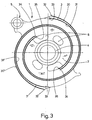
- FIG. 2 is the housing part shown on the left in Fig. 1 7 'of the two axially abutting housing parts 7, 7 'assembled, via mounting eyes 8 for receiving of screw connections 8 'interconnected housing 7 '' shown.
- 11 and 11 ' respectively denote two Conveyor spaces offset by 180 °, which according to Art a spiral slot in each of the two housing parts 7, 7 'are incorporated. They always run one on the radially outer circumference of the spiral in the housing 7 " arranged inlet 12, 12 'to the centrally arranged, two delivery rooms 11, 11 'common outlet 13.
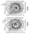
- the displacer 1 is better known Design shown separately.
- they are radial outer and radially inner sealing surfaces 30, 30 'or 31, 31 'forming sections of the strips 3, 3', which on the outer cylinder walls 14, 14 'and inner Cylinder walls 15, 15 'of the machined into the housing parts 7, 7' Funding rooms 11, 11 'for formation and displacement approach the working chambers, entered in bold.
- the inlet side Beginning 32, 33 and the outlet end 34, 35 of the inner sealing surfaces 31, 31 'and outer sealing surfaces 30, 30 ' in the direction of movement of the medium and thus viewed in the circumferential direction, for example opposite.
- the Crosspieces 17, 17 'towards beads protruding inwards 36, which are intended to begin with 32 of the concerned to cooperate with the outer sealing surface 30 or 30 '.
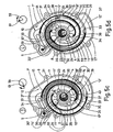
- FIGS. 5a to 5d Shift of beginnings 32, 33 and ends 34, 35 of the sealing surfaces 30, 30 ', 31, 31' on the strips 3, 3 '.
- it is displacer 1 analogous to Fig. 2 inside the housing part 7 ' shown.
- FIG. 5a shows the displacer 1 in a first position, in the outer spiral sealing surface 30 of the strip 3 a first working chamber 41, which is indicated by hatching is included.
- the angle of rotation of the drive is next to the housing 7 '' based on the position of the center of rotation 59 of the drive shaft 24 and the center axis 61 of the eccentric disk 23 shown.
- FIG. 5b shows the displacer 1 in a second position which is the drive with respect to that shown in Fig. 5a Position rotated clockwise by approximately 90 ° Has.
- the working chamber 41 is in this position open on the outlet side and the inner spiral sealing surface 31 the bar 3 closes a second working chamber 42, the also hatched is a.
- This Working chamber 42 has at least approximately the same Size as the working chamber 41.
- FIGS. 5c and 5d show the outside Sealing surface 30 'or inner sealing surface 31' included Working chamber 43 and 44, the further rotation of the drive by about 90 ° angle of rotation be formed.
- FIGS. 5a to 5d it can thus be seen that according to the invention on each side of the disc 2 of the rotor 1 at intervals of approximately 90 ° angle of rotation of the drive in each case a working chamber 41, 42, 43, 44 included becomes.
- the strips 3, 3 ' are opposite the disc 2 of the Displacer 1 arranged symmetrically and the beginnings 32, 33 and ends 34, 35 of the sealing surfaces 30, 30 ', 31, 31' so that the machine operation per revolution of the The resulting working chambers are about the same size are.
Landscapes
- Engineering & Computer Science (AREA)
- Mechanical Engineering (AREA)
- General Engineering & Computer Science (AREA)
- Physics & Mathematics (AREA)
- Geometry (AREA)
- Rotary Pumps (AREA)
- Screw Conveyors (AREA)
- Structures Of Non-Positive Displacement Pumps (AREA)
- Iron Core Of Rotating Electric Machines (AREA)
- Vending Machines For Individual Products (AREA)
Abstract
Description
Die vorliegende Erfindung betrifft eine Verdrängermaschine
für kompressible Medien gemäss dem Oberbegriff des Anspruchs
1.The present invention relates to a displacement machine
for compressible media according to the preamble of the
Eine gattungsbildende Verdrängermaschine nach dem Spiralprinzip ist beispielsweise aus der DE-A-42 03 346 bekannt. Maschinen dieser Art zeichnen sich durch eine Pulsationen von relativ geringer Amplitude aufweisende Förderung des beispielsweise aus Luft oder einem Luft-Kraftstoff-Gemisch bestehenden gasförmigen Arbeitsmediums aus und können daher auch für Aufladezwecke von Brennkraftmaschinen mit Vorteil herangezogen werden. Während des Betriebes einer solchen als Verdichter arbeitenden Verdrängermaschine werden entlang spiralförmiger Förderräumen zwischen ebenfalls spiralförmig ausgebildeten, als Verdrängerkörper wirkenden Leisten und den beiden Zylinderwänden der Förderräume, infolge unterschiedlicher Krümmung der Spiralform mehrere, etwa sichelförmige Arbeitskammern eingeschlossen, die sich von einem Einlass für das Arbeitsmittel durch die Förderräume hindurch zu einem Auslass hin bewegen, wobei ihr Volumen ständig verringert und der Druck des Arbeitsmediums entsprechend erhöht wird. Die beiden jeweils an einer Seite einer exzentrisch angetriebenen Scheibe angeordneten Leisten sind relativ zueinander um etwa 180° versetzt und erstrecken sich über etwa 360°. Jede Leiste weist, in radialer Richtung gesehen, äussere und innere Dichtflächen auf, die beim einlassseitigen Anfang der Leisten beginnen und beim auslassseitigen Ende der Leisten enden. Jede der Leisten bildet somit zusammen mit der entsprechenden Zylinderwand des zugeordneten Förderraumes alle 180° Drehwinkel des Antriebs eine Arbeitskammer.A generic displacement machine based on the spiral principle is known for example from DE-A-42 03 346. Machines of this type are characterized by pulsations of relatively low amplitude promotion of for example from air or an air-fuel mixture existing gaseous working medium and can therefore also for charging internal combustion engines Advantage. During the operation of one such as a positive displacement machine along spiral conveying spaces between also spirally formed, acting as a displacer Strips and the two cylinder walls of the delivery rooms, due to different curvature of the spiral shape, about crescent-shaped work chambers included, which themselves from an inlet for the work equipment through the Move delivery rooms through to an outlet, whereby their volume is constantly decreasing and the pressure of the Working medium is increased accordingly. The two each on one side of an eccentrically driven one Discs arranged strips are relative to each other offset by approximately 180 ° and extend over approximately 360 °. Each ledge has outer faces when viewed in the radial direction and inner sealing surfaces, which at the beginning on the inlet side of the strips start and at the outlet end the last end. Each of the strips thus forms together with the corresponding cylinder wall of the assigned delivery chamber a working chamber every 180 ° angle of rotation of the drive.
Auch die CH-Patentschrift Nr. 673 679 zeigt ausführlich die Art und Weise, wie bei Verdrängermaschinen nach dem Spiralprinzip die Arbeitskammern durch eine kreisende Bewegung der auf der Scheibe des Verdrängers angebrachten Leisten in Zusammenwirkung mit den spiralförmigen Förderräumen im Gehäuse entstehen. Solche Arbeitskammern werden sowohl durch die Innenseite der Leiste als auch durch die Aussenseite begrenzt. Typisch für diese Anordnung ist, dass von einer spiralförmigen Leiste bei der fortschreitenden Drehbewegung der exzentrischen Antriebs- und Führungswellen etwa alle 180° Drehwinkel eine neue Arbeitskammer gebildet wird, respektive der Füllvorgang einer Arbeitskammer abgeschlossen ist.CH Patent Specification No. 673 679 also shows in detail the way, as in displacement machines after the Spiral principle the working chambers by a circular movement the one attached to the disc of the displacer Last in cooperation with the spiral conveyor rooms arise in the housing. Such work chambers will be both through the inside of the bar and through the Outside limited. Typical of this arrangement is that from a spiral ledge as it progresses Rotary movement of the eccentric drive and guide shafts a new working chamber every 180 ° is formed, or the filling process of a working chamber is completed.
Bei den aus der DE-A-42 03 346 und der CH-Patentschrift Nr. 673 679 bekannten Verdrängermaschinen mit vier Förderräumen, wobei auf jeder Seite der Scheibe zwei um ca. 180° gegeneinander versetzte, spiralförmig vom betreffenden Einlass zum Auslass verlaufende, spiegelsymmetrisch angeordnete Förderräume vorhanden sind, schliesst im Maschinenbetrieb jeweils etwa alle 180° Drehwinkel der exzentrischen Antriebs- und Führungswellen ein Füllvorgang der Arbeitskammern ab. Analog zum Füllvorgang der Arbeitskammern verhält sich die Abfolge des Öffnens der Arbeitskammern zum zentralen Auslass hin. In den vier Förderräumen, wie sie beschrieben sind, werden durch die fortschreitende Bewegung der spiralförmigen Leisten, die auf der Scheibe des Läufers gehalten sind, pro volle Umdrehung der Wellen total acht Arbeitsräume gebildet, wovon jeweils vier synchron miteinander arbeiten. Dies führt zu einer niederfrequent pulsierenden Förderung des Arbeitsmediums. Die verbleibende Unregelmässigkeit sowohl des Ansaugvolumenstromes als auch des abgehenden Volumenstromes des Arbeitsmediums erzeugt ein Geräusch mit der Grundfrequenz der doppelten Drehzahl des Antriebs.In those from DE-A-42 03 346 and the CH patent No. 673 679 known displacement machines with four conveying rooms, with two on each side of the disc around 180 ° offset from each other, spiraling from the one in question Mirror-symmetrically arranged inlet to outlet Delivery rooms are available, closes in machine operation about every 180 ° of the eccentric Drive and guide shafts fill the working chambers from. Analogous to the filling process of the working chambers behaves the order of opening the working chambers towards the central outlet. In the four funding areas, such as they are described by the progressive movement of the spiral bars on the disc of the Are held per full revolution of the shafts A total of eight work rooms were created, four of which were synchronized work together. This leads to a low frequency pulsating promotion of the working medium. The remaining one Irregularity of both the intake volume flow as well as the outgoing volume flow of the working medium generates a noise with the fundamental frequency of the double speed of the drive.
Weiter haben bei den bekannten Verdrängermaschinen die bezüglich einer Leiste innenliegenden und aussenliegenden Arbeitskammern unterschiedliche Volumen. Diese Ungleichheit der Arbeitskammern kann zu ungewollten Pulsationen in den Leitungen führen, die das Arbeitsmedium zu der Verdrängermaschine oder von dieser weg leiten.Furthermore, in the known displacement machines, a bar inside and outside Working chambers of different volumes. This inequality the working chambers can cause unwanted pulsations in the lines that lead the working medium to the displacement machine or lead away from it.
Wenn Verdrängermaschinen dieser Art für die Aufladung von Brennkraftmaschinen herangezogen werden, kann dieses niederfrequente Geräusch im Maschinenbetrieb störend wirken. Die Dämpfung dieses Geräusches ist mit einem Mehraufwand sowohl auf der Ansaugseite als auch auf der Förderseite verbunden.When displacement machines of this type for charging Internal combustion engines are used, this can be low-frequency Noise is disruptive during machine operation. The damping of this noise is an additional effort both on the suction side and on the delivery side connected.
Die DE-A-41 33 429 offenbart eine Möglichkeit, die symmetrische Abfolge der Ansaug- und Förderzyklen zu stören. Die darin gezeigte Lösung geht davon aus, die Förderräume im Gehäuse und die spiralförmigen Leisten auf der Scheibe des Läufers untereinander polar so zu verschieben, dass die Abfolge der Ansaug- und Förderzyklen nicht mehr gleichmässig ist. Des weiteren sind die Leisten auf der Scheibe des Läufers nicht mehr spiegelsymmetrisch auf beiden Seiten der Scheibe angeordnet, sondern wiederum winklig bezüglich der Drehachse der exzentrischen Antriebswelle gegeneinander verschoben. Dadurch wird die gewollte Unregelmässigkeit der Ansaug- und Förderzyklen der Maschine weiter erhöht. DE-A-41 33 429 discloses a possibility of symmetrical Disrupt sequence of suction and delivery cycles. The The solution shown therein assumes that the funding areas in the Housing and the spiral strips on the disc of the To shift the rotor polarly so that the Sequence of suction and delivery cycles no longer uniform is. Furthermore, the strips are on the pane the runner no longer mirror-symmetrical on both sides arranged the disc, but again angular with respect the axis of rotation of the eccentric drive shaft against each other postponed. This creates the desired irregularity the suction and delivery cycles of the machine elevated.
Dieser Lösung zur Glättung des Ansaug- und Fördervolumenstromes des Arbeitsmediums haftet jedoch der Nachteil der Asymmetrie der auf die Leisten wirkenden Reaktionskräfte des Arbeitsmediums an. Bei der symmetrischen Ausführung der Verdrängermaschinen nach DE-A-42 03 346 und CH-Patentschrift Nr. 673 679 wirken die Reaktionskräfte, die vom Fördermedium während des Maschinenbetriebes auf die Leisten wirken, symmetrisch und die resultierende Reaktionskraft liegt in der Ebene der Scheibe des Läufers. Dadurch entstehen keine Kräfte, die durch besondere Vorkehrungen abgestützt werden müssten. Bei asymmetrischer Anordnung hingegen, wie sie in der DE-A-41 33 429 offenbart ist, entstehen sehr wohl Kippkräfte, die sowohl durch die ungleiche Belastung, hervorgerufen durch die Reaktionskräfte des Arbeitsmediums, als auch durch die zufolge der asymmetrischen Anordnung der Leisten und dadurch ungleichmässigen Massenverteilung auf der Scheibe hervorgerufen werden. Die zweite Ursache, jene der asymmetrischen Massenverteilung, ist insbesondere bei hohen Drehzahlen schädlich, weil die Trägheits- oder Massenkräfte in solchen Betriebszuständen besonders hoch sind.This solution for smoothing the intake and delivery volume flow However, the disadvantage of the working medium is liable Asymmetry of the reaction forces acting on the groin of the working medium. In the symmetrical version of the displacement machines according to DE-A-42 03 346 and CH patent No. 673 679 the reaction forces act from Pumped medium during machine operation on the Last act symmetrically and the resulting reaction force lies in the plane of the disc of the runner. This does not create any forces caused by special precautions would have to be supported. With asymmetrical Arrangement, however, as disclosed in DE-A-41 33 429 is, tilting forces very well arise, both through the uneven loading caused by the reaction forces the working medium, as well as by the the asymmetrical arrangement of the strips and therefore uneven Mass distribution caused on the disc become. The second cause, that of the asymmetrical Mass distribution, especially at high speeds harmful because the inertial or mass forces in such Operating conditions are particularly high.
Es ist Aufgabe der vorliegenden Erfindung, eine gattungsgemässe Verdrängermaschine zu schaffen, bei deren Betrieb eine fast vollständige Glättung der Pulsationen resultiert.It is an object of the present invention, a generic To create displacement machine in its operation the pulsations are almost completely smoothed out.
Diese Aufgabe wird mit einer Verdrängermaschine gelöst,
die die Merkmale des Anspruchs 1 aufweist.This task is solved with a displacement machine,
having the features of
Die erfindungsgemässe Verdrängermaschine weist bei gegebener Drehzahl des Antriebs eine erhöhte Periodizität der Ansaug- und Förderzyklen auf. Allfällige Pulsationen weisen dadurch nur noch sehr kleine Amplituden auf.The displacement machine according to the invention has given Speed of the drive an increased periodicity of Suction and delivery cycles. Show any pulsations therefore only very small amplitudes.
Weiter lässt die vorliegende Erfindung eine völlig symmetrische Anordnung der Leisten auf der Scheibe zu, was ebenfalls hilft, die Pulsationen sowie Kippmomente auf den Verdränger zu verhindern oder zu vermindern.Furthermore, the present invention leaves a completely symmetrical one Arrangement of the strips on the pane too what helps the pulsations as well as tilting moments on the Prevent or reduce displacers.
Werden die aus der DE-A-42 03 346 und der CH-Patentschrift Nr. 673 679 bekannten Verdrängermaschinen erfindungsgemäss ausgebildet, arbeiten nicht mehr zwei Gruppen zu vier Arbeitskammern miteinander synchron, sondern vier Gruppen zu zwei Arbeitskammern. Es schliessen alle etwa 90° Drehwinkel des Antriebs jeweils zwei Arbeitskammern ihren Ansaugvorgang ab. Das analoge gilt für die Ausschiebevorgänge.Are those from DE-A-42 03 346 and the CH patent No. 673 679 known displacement machines according to the invention trained, no longer work two groups of four working chambers synchronized with each other, but four groups too two working chambers. All close about 90 ° angle of rotation of the drive each two working chambers their suction process from. The same applies to the push-out processes.
In der Zeichnung ist eine Verdrängermaschine mit einem Verdränger bekannter Bauart und ein Ausführungsbeispiel einer erfindungsgemässen Verdrängermaschine dargestellt. Es zeigen rein schematisch:
- Fig. 1
- im Längsschnitt entlang der Linie I-I der Fig. 2 eine Verdrängermaschine;
- Fig. 2
- ein Gehäuseteil des entlang der Linie II-II der Fig. 1 aufgetrennten Gehäuses mit darin inliegendem Verdränger bekannter Bauart;
- Fig. 3
- in Ansicht einen Verdränger bekannter Bauart mit spiralförmigen Leisten;
- Fig. 4
- in Ansicht einen erfindungsgemässen Verdränger;
- Fig. 5a
- in Ansicht ein geöffnetes Gehäuse mit darin angeordnetem Verdränger einer erfindungsgemässen Verdrängermaschine zu einem ersten Zeitpunkt eines Arbeitszyklus, in welchem der Antrieb eine Nullgrad-Ausgangsstellung einnimmt;
- Fig. 5b
- in gleicher Darstellung wie Fig. 5a die dort gezeigte Verdrängermaschine zu einem zweiten Zeitpunkt des Arbeitszyklus, zu welchem der Antrieb um 90° im Uhrzeigersinn rotiert hat;
- Fig. 5c
- in gleicher Darstellung wie Fig. 5a die dort gezeigte Verdrängermaschine zu einem dritten Zeitpunkt des Arbeitszyklus, zu welchem der Antrieb um 180° im Uhrzeigersinn rotiert hat; und
- Fig. 5d
- in gleicher Darstellung wie Fig. 5a die dort gezeigte Verdrängermaschine zu einem vierten Zeitpunkt des Arbeitszyklus, zu welchem der Antrieb um 270° im Uhrzeigersinn rotiert hat.
- Fig. 1
- in longitudinal section along the line II of Figure 2, a positive displacement machine.
- Fig. 2
- a housing part of the housing cut along the line II-II of Figure 1 with a known type of displacer therein;
- Fig. 3
- in view a displacer of known design with spiral strips;
- Fig. 4
- in view a displacer according to the invention;
- Fig. 5a
- in view an open housing with a displacer arranged therein of a displacement machine according to the invention at a first point in time of a work cycle in which the drive assumes a zero degree starting position;
- Fig. 5b
- in the same representation as FIG. 5a, the displacement machine shown there at a second point in time of the working cycle, at which the drive has rotated 90 ° clockwise;
- Fig. 5c
- in the same representation as FIG. 5a, the displacement machine shown there at a third point in the working cycle, at which the drive has rotated clockwise by 180 °; and
- Fig. 5d
- in the same representation as FIG. 5a, the displacement machine shown there at a fourth point in time of the working cycle, at which the drive has rotated clockwise by 270 °.
Mit 1 ist ein Verdränger einer Verdrängermaschine bezeichnet,
der als Läufer in einem Gehäuse 7" angeordnet ist. An
beiden Seiten einer Scheibe 2 des Verdrängers 1 sind je
zwei um wenigstens annähernd 180° zueinander versetzte,
spiralförmig verlaufende Verdrängerkörper angeordnet; es
handelt sich dabei um Leisten 3, 3', die senkrecht auf der
Scheibe 2 gehalten sind. Die Spiralen selbst sind im gezeigten
Beispiel aus mehreren, aneinander anschliessenden
Kreisbögen gebildet. Infolge des aus Fig. 1 ersichtlichen
grossen Verhältnisses zwischen axialer Länge zur Wandstärke,
ist das einlassseitige Ende der Leisten 3, 3' jeweils
verstärkt ausgeführt. Mit 4 ist eine Nabe bezeichnet,
mit welcher die Scheibe 2 auf einem Lager 22 aufgezogen
ist. Das Lager 22 selbst sitzt auf einer Exzenterscheibe
23, die ihrerseits Teil einer Antriebswelle 24
ist. Mit 5 ist ein radial ausserhalb der Leisten 3, 3' angeordnetes
Auge der Scheibe 2 bezeichnet, das ein Führungslager
25 aufnimmt, welches auf einem Exzenterbolzen
26 aufgezogen ist. Dieser ist seinerseits Teil einer ebenfalls
am Gehäuse 7'' gelagerten Führungswelle 27. Die Exzentrizität
e (Fig. 2) der Exzenterscheibe 23 auf der Antriebswelle
24 entspricht jener des Exzenterbolzens 26 auf
der Führungswelle 27. Auslassseitig der Leisten 3, 3' sind
in der Scheibe 2 Durchbrüche 6 vorhanden, damit das Arbeitsmedium
von einer Scheibenseite zur anderen gelangen
kann, beispielsweise um durch einen zentralen Auslass 13
weggeführt zu werden, der an einem in der Fig. 1 rechts
gezeigten Gehäuseteil 7' des Gehäuses 7" angeformt ist.
Mit 19 ist eine Riemenscheibe bezeichnet, die drehfest mit
der Antriebswelle 24 verbunden ist.1 denotes a displacer of a displacement machine,
which is arranged as a rotor in a
Die Antriebswelle 24 ist mittels eines Lagers 58 in einem
in der Fig. 1 links gezeigten Gehäuseteil 7 und mittels
eines Lagers 62 im Gehäuseteil 7' geführt . Durch die Riemenscheibe
19 wird der Verdränger 1 über die Antriebswelle
24 angetrieben. Auf der ebenfalls am Gehäuseteil 7" gelagerten
Führungswelle 27 sitzt drehfest ebenfalls eine
Zahnriemenscheibe 10, die mittels eines Zahnriemens 16 zum
winkelgenauen synchronen Antrieb der Führungswelle 27 mit
der Antriebswelle 24 an die Zahnriemenscheibe 9 gekoppelt
ist. Durch den in dieser Art ausgebildeten Antrieb führt
der Verdränger 1 im Maschinenbetrieb eine kreisende, verdrehungsfreie
Schiebebewegung aus. 40, 40' sind Fliehgewichte,
welche auf der Antriebswelle 24 angebracht sind.
Sie dienen dem Ausgleich der vom Verdränger 1 während des
Maschinenbetriebs auf die Exzenterscheibe 23 wirkenden
Fliehkraft.The
In Fig. 2 ist der in Fig. 1 links dargestellte Gehäuseteil
7' des aus zwei axial aneinander anliegenden Gehäuseteilen
7, 7' zusammengesetzten, über Befestigungsaugen 8 zur Aufnahme
von Verschraubungen 8' miteinander verbundenen Gehäuses
7'' gezeigt. 11 und 11' bezeichnen zwei jeweils um
180° gegeneinander versetzte Förderräume, die nach Art
eines spiralförmigen Schlitzes in jedem der beiden Gehäuseteile
7, 7' eingearbeitet sind. Sie verlaufen von je
einem am radial äusseren Umfang der Spirale im Gehäuse 7"
angeordneten Einlass 12, 12' zum zentral angeordneten,
beiden Förderräumen 11, 11' gemeinsamen Auslass 13. Sie
weisen im wesentlichen parallele, in gleichbleibendem Abstand
zueinander angeordnete Zylinderwände 14, 14', 15,
15' auf, die im vorliegenden Fall, wie die Leisten 3, 3'
auf der Scheibe 2, eine Spirale von ca. 360° umfassen.
Zwischen den Zylinderwänden 14, 14' bzw. 15, 15' greifen
die Leisten 3, 3' ein, deren Krümmung so bemessen ist,
dass sie die radial äusseren und radial inneren Zylinderwände
14, 14' bzw. 15, 15' des Gehäuses 7" in Betrieb an
mehreren, beispielsweise an jeweils zwei Stellen nahezu
berühren. Infolge der durch den Antrieb hervorgerufenen
abwechselnden Annäherung der Leisten 3, 3' an die inneren
Zylinderwände 15, 15' und äusseren Zylinderwände 14, 14'
der zugeordneten Förderräume 11, 11' ergeben sich auf
beiden Seiten der Leisten 3, 3' sichelförmige, das Arbeitsmedium
einschliessende Arbeitskammern, die während
des Antriebs des Verdrängers 1 durch die Förderräume 11,
11' in Richtung auf den Auslass 13 verschoben werden.
Hierbei verringern sich die Volumina dieser Arbeitskammern
und der Druck des Arbeitsmediums wird entsprechend erhöht. In Fig. 2 is the housing part shown on the left in Fig. 1
7 'of the two axially abutting
Bezüglich der grundsätzlichen Arbeitsweise derartiger Verdrängermaschinen wird auch auf DE-C-26 03 462 verwiesen.With regard to the basic mode of operation of such displacement machines reference is also made to DE-C-26 03 462.
Aus Fig. 2 ist weiter erkennbar, dass im Bereich des Einlasses
12' ein Steg 17' mit der äusseren Zylinderwand 14'
sich in einen Steg 18' mit auch der inneren Zylinderwand
15 fortsetzt. Die Massnahme trifft auch im Bereich des
Einlasses 12 zu. Der Übergang erfolgt hier von einem Steg
17 zu einem Steg 18. An den freien Stirnseiten der Leisten
3, 3' und der Stege 17, 17', 18, 18' sind Dichtungen 21 in
entsprechende Nuten eingelegt. Mit ihnen werden die Arbeitsräume
gegen die Seitenwände 28, 28' des Gehäuses,
respektive gegen die Verdrängerscheibe 2 gedichtet.From Fig. 2 it can also be seen that in the area of the inlet
12 'a web 17' with the outer cylinder wall 14 '
in a web 18 'with the
Zur weiteren Veranschaulichung der Arbeitsweise der Verdrängermaschine
ist in Fig. 3 der Verdränger 1 bekannter
Bauart separat dargestellt. In dieser Figur sind die radial
äusseren und radial inneren Dichtflächen 30, 30' bzw.
31, 31' bildenden Abschnitte der Leisten 3, 3', welche
sich an die äusseren Zylinderwände 14, 14' und inneren
Zylinderwände 15, 15' der in die Gehäuseteile 7, 7' eingearbeiteten
Förderräume 11, 11' zur Bildung und Verschiebung
der Arbeitskammern annähern, fett eingetragen.To further illustrate the mode of operation of the
Bei dieser Ausbildung des Verdrängers 1, liegen der einlassseitige
Anfang 32, 33 und das auslassseitige Ende 34,
35 der inneren Dichtflächen 31, 31' und äusseren Dichtflächen
30, 30', in Bewegungsrichtung des Fördermediums
und somit in Umfangsrichtung betrachtet, etwa gegenüber.In this embodiment of the
Fig. 4 zeigt nun einen erfindungsgemäss ausgebildeten Verdränger
1, bei dem die - ebenfalls fett ausgezogenen -
Dichtflächen 30, 31 and 30', 31' an den Leisten 3, 3' in
Umfangsrichtung versetzt angeordnet sind. Der Anfang 32
der jeweils äusseren Dichtfläche 30, 30' ist gegenüber dem
Anfang 33 der jeweils inneren Dichtfläche 31, 31' zum Auslass
13 hin deutlich verschoben. Das entsprechende gilt
für die Enden 34, 35 der äusseren und inneren Dichtflächen
30, 30' bzw. 31, 31'.4 now shows a displacer designed according to the
Wie dies den Fig. 5a bis 5d entnehmbar ist, weisen die
Stege 17, 17' in Richtung gegen innen vorstehende Wülste
36 auf, die dazu bestimmt sind, mit dem Anfang 32 der betreffenden
äusseren Dichtfläche 30 bzw. 30' zusammenzuwirken.
Die Stege 18, 18' sind auf ihrer äusseren Seite mit
einer Vertiefung 37 versehen, die dazu bestimmt ist, mit
dem Anfang 33 der jeweils inneren Dichtfläche 31, 31' zusammenzuwirken.
Weiter weisen die Stege 18, 18' in Richtung
gegen innen vorstehende Verdickungen 38 auf, die zum
Zusammenwirken mit den Enden 34 der äusseren Dichtflächen
30, 30' bestimmt sind. Entsprechend weisen die Leisten 3,
3' beim Ende 35 der inneren Dichtflächen 31, 31' eine
gegen innen vorstehende Verdickung 39 auf, die dazu bestimmt
ist, mit dem diesseitigen Ende der Stege 18, 18'
zusammenzuwirken.As can be seen in FIGS. 5a to 5d, the
Aus den Fig. 5a bis 5d geht die Wirkungsweise der erfindungsgemässen
Verschiebung der Anfänge 32, 33 und Enden
34, 35 der Dichtflächen 30, 30', 31, 31' an den Leisten 3,
3' hervor. Der besseren Übersichtlichkeit halber ist der
verdränger 1 analog Fig. 2 im Gehäuseteil 7' innenliegend
dargestellt.The mode of operation of the inventive method is shown in FIGS. 5a to 5d
Shift of
Fig. 5a zeigt den Verdränger 1 in einer ersten Lage, in
der die äussere Spiraldichtfläche 30 der Leiste 3 eine
erste Arbeitskammer 41, die schraffiert gekennzeichnet
ist, eingeschlossen hat. Die Drehwinkellage des Antriebs
ist neben dem Gehäuse 7'' anhand der Lage des Rotationszentrums
59 der Antriebswelle 24 und der Zentrumsachse
61 der Exzenterscheibe 23 gezeigt.5a shows the
Fig. 5b zeigt den Verdränger 1 in einer zweiten Lage, bei
welcher der Antrieb bezüglich der in der Fig. 5a gezeigten
Lage im Uhrzeigersinn um etwa 90° Drehwinkelabstand gedreht
hat. In dieser Lage ist die Arbeitskammer 41
auslassseitig offen und die innere Spiraldichtfläche 31
der Leiste 3 schliesst eine zweite Arbeitskammer 42, die
ebenfalls schraffiert gekennzeichnet ist ein. Diese
Arbeitskammer 42 hat wenigstens annähernd die gleiche
Grösse wie die Arbeitskammer 41.5b shows the
Entsprechend zeigen die Fig. 5c und 5d von der äusseren
Dichtfläche 30' bzw. inneren Dichtfläche 31' eingeschlossene
Arbeitskammer 43 und 44, die bei weiterer Drehung
des Antriebs um jeweils etwa 90° Drehwinkelabstand
gebildet werden.Correspondingly, FIGS. 5c and 5d show the outside
Sealing surface 30 'or inner sealing surface 31' included
Aus den Fig. 5a bis 5d geht somit hervor, dass erfindungsgemäss
auf jeder Seite der Scheibe 2 des Läufers 1 in Abständen
von etwa 90° Drehwinkelabstand des Antriebs jeweils
eine Arbeitskammer 41, 42, 43, 44 eingeschlossen
wird. Die Leisten 3, 3' sind gegenüber der Scheibe 2 des
Verdrängers 1 symmetrisch angeordnet und die Anfänge 32,
33 und Enden 34, 35 der Dichtflächen 30, 30', 31, 31' sind
so gelegt, dass die im Maschinenbetrieb pro Umdrehung des
Antriebs entstehenden Arbeitskammern etwa gleich gross
sind.From FIGS. 5a to 5d it can thus be seen that according to the invention
on each side of the
Claims (6)
- A displacement machine for compressible media, having at least two delivery spaces (11, 11') which are arranged in a housing (7") and lead spirally from a radially outer inlet (12, 12') to a radially inner outlet (13), and having a displacer (1) which, when operating, executes a circulating but non-rotating movement, has a disk (2) and spiral bars (3, 3') arranged on a side of the disk (2), the bars, as viewed in the radial direction, having outer and inner sealing faces (30, 30', 31, 31') which cooperate with outer and inner cylindrical walls (14, 14', 15, 15') of the delivery spaces (11, 11') in order, when operating, to form working chambers (41, 42, 43, 44) that move from the inlet (12, 12') to the outlet (13), wherein the outer and inner sealing faces (30, 30', 31, 31') of the bars (3, 3') are offset, as viewed in the circumferential direction, in order to form a working chamber (41, 42, 43, 44) each in a uniform rotational angle interval of the movement of the displacer (1).
- The displacement machine as claimed in claim 1, wherein the outer and inner sealing faces (30, 30', 31, 31') have beginnings (32, 33) on the inlet side which are arranged on the bars (3, 3') in such a way that, at least approximately in the rotational angle interval of 90°, a working chamber (41, 42, 43, 44) is in each case closed.
- The displacement machine as claimed in claim 1 or 2, wherein the outer and inner sealing faces (30, 30', 31, 31') have ends (34, 35) on the outlet side which are arranged on the bars (3, 3') in such a way that, at least approximately in the rotational angle interval of 90°, a working chamber (41, 42, 43, 44) is in each case opened.
- The displacement machine as claimed in one of claims 1 to 3, wherein on one side of the disk (2) two bars (3, 3') are arranged so that they are offset by 180°, and on each bar (3, 3') the outer sealing face (30, 30') is arranged so that it is offset in relation to the inner sealing face (31, 31') by at least approximately a rotational angle interval of 90°.
- The displacement machine as claimed in one of claims 1 to 4, wherein the beginnings (32, 33) on the inlet side and the ends (34, 35) on the outlet side of the outer and inner sealing faces (30, 30', 31, 31') are arranged on the bars (3, 3') in such a way that the working chambers (41, 42, 43, 44) are at least approximately equally large when closed and at least approximately equally large when opened.
- The displacement machine as claimed in one of claims 1 to 5, wherein bars (3, 3') are arranged on both sides of the disk (2), with mirror symmetry to the latter, and cooperate with associated delivery spaces (11, 11').
Applications Claiming Priority (3)
| Application Number | Priority Date | Filing Date | Title |
|---|---|---|---|
| CH198397 | 1997-08-26 | ||
| CH1983/97 | 1997-08-26 | ||
| CH198397 | 1997-08-26 |
Publications (2)
| Publication Number | Publication Date |
|---|---|
| EP0899423A1 EP0899423A1 (en) | 1999-03-03 |
| EP0899423B1 true EP0899423B1 (en) | 2002-12-11 |
Family
ID=4223171
Family Applications (1)
| Application Number | Title | Priority Date | Filing Date |
|---|---|---|---|
| EP98115305A Expired - Lifetime EP0899423B1 (en) | 1997-08-26 | 1998-08-14 | Scroll compressible fluid displacement machine |
Country Status (7)
| Country | Link |
|---|---|
| US (1) | US6116875A (en) |
| EP (1) | EP0899423B1 (en) |
| JP (1) | JPH11132162A (en) |
| CN (1) | CN1210936A (en) |
| AT (1) | ATE229612T1 (en) |
| CA (1) | CA2245629A1 (en) |
| DE (1) | DE59806600D1 (en) |
Families Citing this family (16)
| Publication number | Priority date | Publication date | Assignee | Title |
|---|---|---|---|---|
| US20040148951A1 (en) * | 2003-01-24 | 2004-08-05 | Bristol Compressors, Inc, | System and method for stepped capacity modulation in a refrigeration system |
| GB0319513D0 (en) * | 2003-08-19 | 2003-09-17 | Boc Group Plc | Scroll compressor and scroll wall arrangement therefor |
| ATE533920T1 (en) * | 2007-08-22 | 2011-12-15 | Spinnler Engineering | DISPLACEMENT MACHINE ACCORDING TO THE SPIRAL PRINCIPLE |
| EP2280148B1 (en) * | 2008-04-07 | 2018-09-12 | Mitsubishi Electric Corporation | Scroll fluid machine |
| DE202008006927U1 (en) | 2008-05-21 | 2008-07-31 | Handtmann Systemtechnik Gmbh & Co. Kg | Rib design for a supercharger based on the spiral principle |
| DE202008006926U1 (en) | 2008-05-21 | 2008-07-31 | Handtmann Systemtechnik Gmbh & Co. Kg | Swing arm bearing with a supercharger according to the spiral principle |
| DE102010025986A1 (en) | 2010-07-02 | 2012-01-05 | Handtmann Systemtechnik Gmbh & Co. Kg | Charging device e.g. scroll type supercharger for internal combustion engine, has rotary shaft seal that includes ring housing and seat, where ring housing and outer portion of seat are partially formed with same light metal |
| DE102010025988A1 (en) | 2010-07-02 | 2012-01-26 | Handtmann Systemtechnik Gmbh & Co. Kg | Charging device for the compression of charge air |
| DE102010025985B4 (en) | 2010-07-02 | 2017-11-02 | Handtmann Systemtechnik Gmbh & Co. Kg | Charging device for the compression of charge air |
| DE102011103165A1 (en) | 2010-07-02 | 2012-01-05 | Handtmann Systemtechnik Gmbh & Co. Kg | Charging device for compressing charge air for an internal combustion engine |
| DE102012019040B4 (en) | 2012-09-28 | 2014-08-14 | Harald Teinzer | Scroll engine |
| CN103511293B (en) * | 2013-10-14 | 2016-05-18 | 黄少平 | A kind of air force energizer |
| FR3027633B1 (en) * | 2014-10-27 | 2016-12-09 | Danfoss Commercial Compressors | SPIRAL COMPRESSOR |
| EP3056662B1 (en) | 2015-02-11 | 2018-12-12 | Danfoss A/S | Vane cell machine |
| DE102015220130B4 (en) * | 2015-10-15 | 2020-01-30 | Handtmann Systemtechnik Gmbh & Co. Kg | Compressor device for an internal combustion engine, drive device, motor vehicle |
| DE102023126031A1 (en) * | 2023-09-26 | 2025-03-27 | Zf Cv Systems Global Gmbh | Scroll compressor arrangement |
Family Cites Families (13)
| Publication number | Priority date | Publication date | Assignee | Title |
|---|---|---|---|---|
| CH586348A5 (en) * | 1975-02-07 | 1977-03-31 | Aginfor Ag | |
| JPS60104788A (en) * | 1983-11-14 | 1985-06-10 | Sanden Corp | Scroll compressor |
| CH667497A5 (en) * | 1985-04-26 | 1988-10-14 | Bbc Brown Boveri & Cie | ROTARY PISTON DISPLACEMENT MACHINE. |
| CH673874A5 (en) * | 1987-03-24 | 1990-04-12 | Bbc Brown Boveri & Cie | |
| CH673680A5 (en) * | 1987-12-21 | 1990-03-30 | Bbc Brown Boveri & Cie | |
| CH673679A5 (en) * | 1987-12-21 | 1990-03-30 | Bbc Brown Boveri & Cie | |
| US5171140A (en) * | 1990-10-19 | 1992-12-15 | Volkswagen Ag | Spiral displacement machine with angularly offset spiral vanes |
| DE4133428C2 (en) * | 1990-10-19 | 2002-12-12 | Volkswagen Ag | Spiralverdrängermaschine |
| DE4133429A1 (en) * | 1990-10-19 | 1992-04-23 | Volkswagen Ag | SPIRAL DISPLACEMENT MACHINE |
| DE4203346A1 (en) | 1991-02-18 | 1992-08-20 | Volkswagen Ag | DISPLACEMENT MACHINE |
| JPH0579462A (en) * | 1991-04-10 | 1993-03-30 | Mitsuba Electric Mfg Co Ltd | Scroll pump |
| JPH07503051A (en) * | 1992-01-27 | 1995-03-30 | フオード モーター カンパニー | scroll compressor |
| JPH0979151A (en) * | 1995-09-11 | 1997-03-25 | Sanyo Electric Co Ltd | Scroll compressor |
-
1998
- 1998-08-14 EP EP98115305A patent/EP0899423B1/en not_active Expired - Lifetime
- 1998-08-14 DE DE59806600T patent/DE59806600D1/en not_active Expired - Fee Related
- 1998-08-14 AT AT98115305T patent/ATE229612T1/en not_active IP Right Cessation
- 1998-08-20 JP JP10234061A patent/JPH11132162A/en active Pending
- 1998-08-25 CA CA002245629A patent/CA2245629A1/en not_active Abandoned
- 1998-08-26 CN CN98120353A patent/CN1210936A/en active Pending
- 1998-08-26 US US09/140,675 patent/US6116875A/en not_active Expired - Fee Related
Also Published As
| Publication number | Publication date |
|---|---|
| CN1210936A (en) | 1999-03-17 |
| EP0899423A1 (en) | 1999-03-03 |
| ATE229612T1 (en) | 2002-12-15 |
| US6116875A (en) | 2000-09-12 |
| JPH11132162A (en) | 1999-05-18 |
| DE59806600D1 (en) | 2003-01-23 |
| CA2245629A1 (en) | 1999-02-26 |
Similar Documents
| Publication | Publication Date | Title |
|---|---|---|
| EP0899423B1 (en) | Scroll compressible fluid displacement machine | |
| DE4241320C2 (en) | Rotary engine | |
| EP0354342B1 (en) | Scroll-type fluid displacement machine | |
| EP0392975B1 (en) | Rotary scroll supercharger for compressible media | |
| EP0371305B1 (en) | Excentric shaft with a counter weight | |
| EP0614012B1 (en) | Scroll type positive displacement machine | |
| EP0321781B1 (en) | Fluid displacement apparatus with a spiral element | |
| EP0284774A1 (en) | Scroll-type displacement machine | |
| EP0547470B1 (en) | Positive displacement machine of the spiral principle | |
| DE1653921B2 (en) | Rotary piston pump | |
| EP0545190B1 (en) | Scroll-type fluid displacement machine | |
| DE2313587A1 (en) | ROTARY COMPRESSOR | |
| EP1005604B1 (en) | Rotary piston machine | |
| EP0899424A1 (en) | Scroll compressible fluid displacement machine | |
| EP0560009A1 (en) | Positive displacement machine on the spiral principle | |
| DE2533776A1 (en) | ROTATING MOTOR | |
| DE3525933C2 (en) | ||
| EP0545191B1 (en) | Scroll-type fluid displacement machine | |
| DE3404222C2 (en) | ||
| DE3727281A1 (en) | Rotary displacement compressor | |
| DE2229532C3 (en) | Rotary piston machine | |
| EP0841484A1 (en) | Rotary pump | |
| EP0597804A1 (en) | Fluid displacement apparatus with a spiral element | |
| WO1997013957A1 (en) | Rotary piston engine | |
| EP0545188B1 (en) | Scroll type fluid displacement machine |
Legal Events
| Date | Code | Title | Description |
|---|---|---|---|
| PUAI | Public reference made under article 153(3) epc to a published international application that has entered the european phase |
Free format text: ORIGINAL CODE: 0009012 |
|
| AK | Designated contracting states |
Kind code of ref document: A1 Designated state(s): AT BE CH DE ES FR GB IE IT LI NL SE |
|
| AX | Request for extension of the european patent |
Free format text: AL;LT;LV;MK;RO;SI |
|
| 17P | Request for examination filed |
Effective date: 19990820 |
|
| AKX | Designation fees paid |
Free format text: AT BE CH DE ES FR GB IE IT LI NL SE |
|
| RAP1 | Party data changed (applicant data changed or rights of an application transferred) |
Owner name: CRT COMMON RAIL TECHNOLOGIES AG |
|
| GRAG | Despatch of communication of intention to grant |
Free format text: ORIGINAL CODE: EPIDOS AGRA |
|
| 17Q | First examination report despatched |
Effective date: 20020429 |
|
| GRAG | Despatch of communication of intention to grant |
Free format text: ORIGINAL CODE: EPIDOS AGRA |
|
| GRAH | Despatch of communication of intention to grant a patent |
Free format text: ORIGINAL CODE: EPIDOS IGRA |
|
| GRAH | Despatch of communication of intention to grant a patent |
Free format text: ORIGINAL CODE: EPIDOS IGRA |
|
| GRAA | (expected) grant |
Free format text: ORIGINAL CODE: 0009210 |
|
| AK | Designated contracting states |
Kind code of ref document: B1 Designated state(s): AT BE CH DE ES FR GB IE IT LI NL SE |
|
| PG25 | Lapsed in a contracting state [announced via postgrant information from national office to epo] |
Ref country code: NL Free format text: LAPSE BECAUSE OF FAILURE TO SUBMIT A TRANSLATION OF THE DESCRIPTION OR TO PAY THE FEE WITHIN THE PRESCRIBED TIME-LIMIT Effective date: 20021211 Ref country code: IT Free format text: LAPSE BECAUSE OF FAILURE TO SUBMIT A TRANSLATION OF THE DESCRIPTION OR TO PAY THE FEE WITHIN THE PRE;WARNING: LAPSES OF ITALIAN PATENTS WITH EFFECTIVE DATE BEFORE 2007 MAY HAVE OCCURRED AT ANY TIME BEFORE 2007. THE CORRECT EFFECTIVE DATE MAY BE DIFFERENT FROM THE ONE RECORDED.SCRIBED TIME-LIMIT Effective date: 20021211 Ref country code: IE Free format text: LAPSE BECAUSE OF FAILURE TO SUBMIT A TRANSLATION OF THE DESCRIPTION OR TO PAY THE FEE WITHIN THE PRESCRIBED TIME-LIMIT Effective date: 20021211 Ref country code: GB Free format text: LAPSE BECAUSE OF FAILURE TO SUBMIT A TRANSLATION OF THE DESCRIPTION OR TO PAY THE FEE WITHIN THE PRESCRIBED TIME-LIMIT Effective date: 20021211 Ref country code: FR Free format text: LAPSE BECAUSE OF NON-PAYMENT OF DUE FEES Effective date: 20021211 |
|
| REF | Corresponds to: |
Ref document number: 229612 Country of ref document: AT Date of ref document: 20021215 Kind code of ref document: T |
|
| REG | Reference to a national code |
Ref country code: GB Ref legal event code: FG4D Free format text: NOT ENGLISH |
|
| REG | Reference to a national code |
Ref country code: CH Ref legal event code: EP |
|
| REG | Reference to a national code |
Ref country code: IE Ref legal event code: FG4D Free format text: GERMAN |
|
| REF | Corresponds to: |
Ref document number: 59806600 Country of ref document: DE Date of ref document: 20030123 |
|
| PG25 | Lapsed in a contracting state [announced via postgrant information from national office to epo] |
Ref country code: SE Free format text: LAPSE BECAUSE OF FAILURE TO SUBMIT A TRANSLATION OF THE DESCRIPTION OR TO PAY THE FEE WITHIN THE PRESCRIBED TIME-LIMIT Effective date: 20030311 |
|
| NLV1 | Nl: lapsed or annulled due to failure to fulfill the requirements of art. 29p and 29m of the patents act | ||
| GBV | Gb: ep patent (uk) treated as always having been void in accordance with gb section 77(7)/1977 [no translation filed] |
Effective date: 20021211 |
|
| PG25 | Lapsed in a contracting state [announced via postgrant information from national office to epo] |
Ref country code: ES Free format text: LAPSE BECAUSE OF FAILURE TO SUBMIT A TRANSLATION OF THE DESCRIPTION OR TO PAY THE FEE WITHIN THE PRESCRIBED TIME-LIMIT Effective date: 20030627 |
|
| REG | Reference to a national code |
Ref country code: IE Ref legal event code: FD4D Ref document number: 0899423E Country of ref document: IE |
|
| PG25 | Lapsed in a contracting state [announced via postgrant information from national office to epo] |
Ref country code: AT Free format text: LAPSE BECAUSE OF NON-PAYMENT OF DUE FEES Effective date: 20030814 |
|
| PG25 | Lapsed in a contracting state [announced via postgrant information from national office to epo] |
Ref country code: LI Free format text: LAPSE BECAUSE OF NON-PAYMENT OF DUE FEES Effective date: 20030831 Ref country code: CH Free format text: LAPSE BECAUSE OF NON-PAYMENT OF DUE FEES Effective date: 20030831 Ref country code: BE Free format text: LAPSE BECAUSE OF NON-PAYMENT OF DUE FEES Effective date: 20030831 |
|
| PLBE | No opposition filed within time limit |
Free format text: ORIGINAL CODE: 0009261 |
|
| STAA | Information on the status of an ep patent application or granted ep patent |
Free format text: STATUS: NO OPPOSITION FILED WITHIN TIME LIMIT |
|
| EN | Fr: translation not filed | ||
| 26N | No opposition filed |
Effective date: 20030912 |
|
| BERE | Be: lapsed |
Owner name: COMMON RAIL TECHNOLOGIES A.G. *CRT Effective date: 20030831 |
|
| PG25 | Lapsed in a contracting state [announced via postgrant information from national office to epo] |
Ref country code: DE Free format text: LAPSE BECAUSE OF NON-PAYMENT OF DUE FEES Effective date: 20040302 |
|
| REG | Reference to a national code |
Ref country code: CH Ref legal event code: PL |