EP0284774A1 - Scroll-type displacement machine - Google Patents
Scroll-type displacement machine Download PDFInfo
- Publication number
- EP0284774A1 EP0284774A1 EP88102699A EP88102699A EP0284774A1 EP 0284774 A1 EP0284774 A1 EP 0284774A1 EP 88102699 A EP88102699 A EP 88102699A EP 88102699 A EP88102699 A EP 88102699A EP 0284774 A1 EP0284774 A1 EP 0284774A1
- Authority
- EP
- European Patent Office
- Prior art keywords
- housing
- disk
- web
- disc
- delivery
- Prior art date
- Legal status (The legal status is an assumption and is not a legal conclusion. Google has not performed a legal analysis and makes no representation as to the accuracy of the status listed.)
- Granted
Links
Images

Classifications
-
- F—MECHANICAL ENGINEERING; LIGHTING; HEATING; WEAPONS; BLASTING
- F01—MACHINES OR ENGINES IN GENERAL; ENGINE PLANTS IN GENERAL; STEAM ENGINES
- F01C—ROTARY-PISTON OR OSCILLATING-PISTON MACHINES OR ENGINES
- F01C1/00—Rotary-piston machines or engines
- F01C1/02—Rotary-piston machines or engines of arcuate-engagement type, i.e. with circular translatory movement of co-operating members, each member having the same number of teeth or tooth-equivalents
- F01C1/0207—Rotary-piston machines or engines of arcuate-engagement type, i.e. with circular translatory movement of co-operating members, each member having the same number of teeth or tooth-equivalents both members having co-operating elements in spiral form
- F01C1/0246—Details concerning the involute wraps or their base, e.g. geometry
- F01C1/0269—Details concerning the involute wraps
- F01C1/0276—Different wall heights
Definitions
- the invention relates to a positive displacement machine for compressible media with at least four conveying spaces arranged in a fixed housing, with four conveying spaces, each housing half having two conveying spaces which are offset from one another by approximately 180.degree. And spiraling from an inlet to an outlet, and wherein each conveying space is an in is assigned to this engaging displacement body, which is held as a spiral bar vertically on a disc-shaped rotor which can be driven eccentrically with respect to the housing, for guiding it in the housing a second guide eccentric arrangement arranged at a distance from the first drive eccentric arrangement is provided.
- Displacement machines of the type mentioned are known, for example, from DE-C3-2 603 462. These machines are characterized by an almost pulsation-free conveyance of the gaseous working medium, which consists for example of air or an air / fuel mixture, and can therefore also be used with advantage for charging purposes of internal combustion engines.
- the gaseous working medium which consists for example of air or an air / fuel mixture
- Displacement machines are characterized by an almost pulsation-free conveyance of the gaseous working medium, which consists for example of air or an air / fuel mixture, and can therefore also be used with advantage for charging purposes of internal combustion engines.
- the displacement bodies are formed by spiral strips, which are held essentially vertically on the disk-shaped rotor and have a relatively large axial length in relation to their thickness. Similar conditions exist on the side of the fixed housing, where also spiral-shaped, strip-like webs remain between the conveying chambers with a relatively large length in relation to the wall thickness in the axial and in the circumferential direction.
- a precise rolling of a displacement body according to the spiral principle by a translatory circular movement can be achieved by a double crank drive, as is known for example from DE-A-3 107 231 and in which one crank drives and the second crank guides.
- the longitudinal gaps are delimited by overlapping, radial surfaces of the housing, the guide element and the displacer.
- the invention seeks to remedy this. It is based on the task of configuring a machine of the type mentioned at the outset in such a way that it has the advantages of the second type, i.e. is equipped with a small diameter and thus low weight and volume.
- this is achieved in that the web with the outer cylinder wall of the one delivery chamber continues in the region of the inflow part of the second delivery chamber offset by approximately 180 ° as a web with the inner cylinder wall of this second delivery chamber, that the disk closes radially with the strips and penetrates the housing in the area of the inlets of the spirals, for which purpose the inner cylinder walls of the delivery chambers on one housing half are lowered by the amount of the disk thickness and the transition between raised outer and lowered inner cylinder wall is designed as a circular shoulder, and during machine operation in the periods , in which different pressures prevail in radially adjacent conveying spaces, this circular shoulder is intended to form a sealing line extending over the heel height and cooperates with an arcuate recess in the disk.
- the invention is based on the idea that, on the occasion of the circular movement, only those conveying spaces in which the same pressure prevails communicate with one another.
- the seal is effective at different pressures in the adjacent rooms.
- this principle is only possible if at least two spirals are nested.
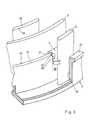
- FIGS. 1 and 2 For the sake of clarity, the machine is shown in the disassembled state in FIGS. 1 and 2.
- the drive is not shown because it is not essential to the invention; it is only hinted at in Fig. 1.
- the rotor of the machine as a whole is designated by 1 in FIG. 2.
- Arranged on both sides of the disk 2 are two, displaced by 180 ° to each other, spirally extending displacement body. These are strips 3.3 ⁇ , which are held vertically on the disc 2.
- the spirals themselves are formed from a plurality of circular arcs adjoining one another.
- the lower housing half 7 is composed of two halves, via mounting eyes 8 for receiving Ver Connected machine housing shown screw connections.
- 9 symbolizes the holder for the drive shaft
- 10 the holder for the guide shaft.
- 11 and 11 ⁇ denote the two delivery spaces, each offset by 180 °, which are incorporated in the manner of a spiral slot in the two housing halves. They each run from an inlet 12, 12 ⁇ arranged on the outer circumference of the spiral in the housing to an outlet 13 provided in the interior of the housing and common to both delivery spaces. They have essentially parallel cylinder walls 14, 14 ⁇ , 15, 15 annosti arranged at a constant distance from one another, which in the present case, like the displacement bodies of the disk 2, comprise a spiral of approximately 360 °. Between these cylinder walls engage the displacer 3.3 ⁇ , the curvature of which is dimensioned such that the strips almost touch the inner and outer cylinder walls of the housing at several, for example at two points each.
- the drive and the guide of the rotor 1 are provided by the two spaced-apart eccentric arrangements (4.9 and 5.10, respectively).
- the two eccentric arrangements are synchronized by an indicated toothed belt drive 16 with precise angles. This double eccentric drive ensures that all points of the rotor disc and thus all points of the two strips 3 and 3 ⁇ perform a circular displacement movement.
- crescent-shaped workspaces including the working medium, result on both sides of the strips rend the drive of the rotor disk through the delivery chambers in the direction of the outlet.
- the volumes of these workspaces decrease and the pressure of the work equipment is increased accordingly.
- Fig. 1 shows that the disc 2 - apart from the radially projecting Aufge 5 - closes radially with the strips 3.3 ⁇ .
- the disk must penetrate at least one half of the housing in the radial direction in the area of the inlets 12, 12 ⁇ . In the present case, this is done on the lower housing half 7.
- the inner webs 18, 18 ⁇ thereof are lowered by the amount of the pane thickness compared to the outer webs 17, 17 ⁇ .
- This measure has the advantage that, in the lower half of the housing, sealing strips are only to be arranged on the inner webs 18, 18 ', which seal the delivery spaces 11, 11' against each other via the disk 2 up to the outlet.
- this transition is now designed as a circular shoulder 19, 19 ⁇ with the radius R1.
- the counter surface on the disc 2 is provided with a corresponding circular arc-shaped cutout 20, 20 ⁇ , the radius R2 of this cutout corresponding to the eccentricity e + radium R1.
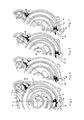
- 4 to 7 show how these paragraphs 19, 19,1 cooperate with the circular arc-shaped recesses 20, 20 ⁇ on the occasion of machine operation to form a sealing line 21.
- the suction in the outer delivery chamber 11a has just ended.
- the strip 3 lies (not shown) on both the inlet 12 and the outlet 13 on the outer cylinder wall 14.
- the suction process in the inner delivery chamber 11 ⁇ i is ended, ie the bar 3 ⁇ lies on the inlet and outlet sides on the inner cylinder wall 15 ⁇ at. Since the conveying process resp. Depending on the spiral configuration, the compression process begins in the crescent-shaped, closed work rooms, sealing at point A is necessary so that the conveyed medium cannot escape into the inlet 12 ⁇ . On the other hand, this is not necessary, since both the inner delivery space 11i and the outer delivery space 11a to their respective inlets 12 and. 12 ⁇ are open.
- the 270 ° angular position shows the permanent seal in A ⁇ and the unnecessary seal in inlet 12 ⁇ , since there both the inner and the outer delivery chambers open to their inlets and there is pressure equilibrium.
Abstract
Description
Die Erfindung betrifft eine Verdrängermaschine für kompressible Medien mit mindestens vier in einem feststehenden Gehäuse angeordneten Förderräumen, wobei bei vier Förderräumen jede Gehäusehälfte zwei um ca. 180° gegeneinander versetzte und spiralförmig von einem Einlass zu einem Auslass verlaufende Förderräume aufweist, und wobei jedem Förderraum ein in diesen eingreifenden Verdrängerkörper zugeordnet ist, der als spiralförmige Leiste senkrecht auf einem gegenüber dem Gehäuse exzentrisch antreibbaren scheibenförmigen Läufer gehalten ist, zu dessen Führung im Gehäuse eine zur ersten Antriebsexzenteranordnung mit Abstand angeordnete zweite Führungsexzenteranordnung vorgesehen ist.The invention relates to a positive displacement machine for compressible media with at least four conveying spaces arranged in a fixed housing, with four conveying spaces, each housing half having two conveying spaces which are offset from one another by approximately 180.degree. And spiraling from an inlet to an outlet, and wherein each conveying space is an in is assigned to this engaging displacement body, which is held as a spiral bar vertically on a disc-shaped rotor which can be driven eccentrically with respect to the housing, for guiding it in the housing a second guide eccentric arrangement arranged at a distance from the first drive eccentric arrangement is provided.
Verdrängermaschinen der genannten Art sind beispielsweise aus der DE-C3-2 603 462 bekannt. Diese Maschinen zeichnen sich durch eine nahezu pulsationsfreie Förderung des beispielsweise aus Luft oder einem Luft-Kraftstoff-Gemisch bestehenden gasförmigen Arbeitsmittel aus und können daher auch für Aufladezwecke von Brennkraftmaschinen mit Vorteil herangezogen werden. Während des Betriebes einer solchen als Verdichter arbeitenden Verdrängermaschine wer den entlang der Förderkammer zwischen dem spiralförmig ausgebildeten Verdrängerkörper und den beiden Zylinderwänden der Förderkammer infolge unterschiedlicher Krümmung der Spiralformen mehrere, etwa sichelförmige Arbeitsräume eingeschlossen, die sich von einem Arbeitsmitteleinlass durch die Förderkammer hindurch zu einem Arbeitsmittelauslass hin bewegen, wobei ihr Volumen ständig verringert und der Druck des Arbeitsmittels entsprechend erhöht wird. Die Verdrängerkörper werden durch auf dem scheibenförmigen Läufer im wesentlichen senkrecht stehend gehaltene, spiralförmige Leisten gebildet, die eine relativ grosse axiale Länge im Verhältnis zu ihrer Stärke aufweisen. Aehnliche Verhältnisse liegen auf der Seite des feststehenden Gehäuses vor, wo zwischen den Förderkammern ebenfalls sprialförmige, leistenartige Stege stehenbleiben mit im Verhältnis zur Wandstärke relativ grosser Länge in axialer und in Umfangsrichtung.Displacement machines of the type mentioned are known, for example, from DE-C3-2 603 462. These machines are characterized by an almost pulsation-free conveyance of the gaseous working medium, which consists for example of air or an air / fuel mixture, and can therefore also be used with advantage for charging purposes of internal combustion engines. During the operation of such a displacement machine working as a compressor enclosed along the conveying chamber between the spiral-shaped displacement body and the two cylinder walls of the conveying chamber as a result of different curvature of the spiral shapes, several approximately crescent-shaped work spaces, which move from a working medium inlet through the conveying chamber to a working medium outlet, their volume constantly decreasing and the pressure of the work equipment is increased accordingly. The displacement bodies are formed by spiral strips, which are held essentially vertically on the disk-shaped rotor and have a relatively large axial length in relation to their thickness. Similar conditions exist on the side of the fixed housing, where also spiral-shaped, strip-like webs remain between the conveying chambers with a relatively large length in relation to the wall thickness in the axial and in the circumferential direction.
Eine präzise Abwälzung eines Verdrängerkörpers nach dem Spiralprinzip durch eine translatorische Kreisbewegung kann durch einen Doppelkurbeltrieb erreicht werden, wie er beispielsweise aus der DE-A-3 107 231 bekannt ist und bei dem eine Kurbel antreibt und die zweite Kurbel führt.A precise rolling of a displacement body according to the spiral principle by a translatory circular movement can be achieved by a double crank drive, as is known for example from DE-A-3 107 231 and in which one crank drives and the second crank guides.
Durch Fertigungsabweichungen verursachte ungenaue Parallelführung des eine grosse axiale Breite aufweisenden Verdrängerkörpers zum Gehäuse stellt ein grosses Problem dar. Abhilfe wurde hierzu in der DE-A-3 231 756 vorgeschlagen in der Weise, dass das Führungselement nicht aus einer Kurbel, sondern aus einer einerseits am Gehäuse und andererseits am Verdrängungskörper angelenkten Kurbelschwinge besteht, deren Länge grösser ist als die Länge der Antriebskurbel. Auch hier sind die spiralförmigen Leisten axial abstehend auf einer eine Nabe zur Lagerung des exzentrischen Kurbeltriebes aufweisenden Scheibe angeordnet. Die Scheibe schliesst radial mit der Leiste ab, wobei dann der bewegungbedingte veränderliche Spalt zwischen Gehäuse und Verdrängerkörper durch spezielle Ausbildung des Führungselementes berührungsfrei minimiert ist. Die Längsspalten werden dabei durch überlappende, radienförmige Flächen des Gehäuses, des Führungselementes und des Verdrängerkörpers begrenzt. Ein Vorteil dieser Führungsart und Abdich tungsart ist darin zu sehen, dass der Durchmesser des scheibenförmigen Läufers und damit auch des Gehäuses um die zweifache Kurbellänge verringert werden kann.Inaccurate parallel guidance of the displacer body, which has a large axial width, to the housing, caused by manufacturing deviations, is a major problem. Remedy was proposed in DE-A-3 231 756 in such a way that the guide element does not consist of a crank, but instead of a crank on the one hand Housing and on the other hand on the displacement arm hinged crank arm, the length of which is greater than the length of the drive crank. Here, too, the spiral strips are axially projecting on a disk having a hub for mounting the eccentric crank mechanism. The disc closes radially with the bar, the movement-dependent variable gap between the housing and the displacer body being minimized in a contact-free manner by means of a special design of the guide element. The longitudinal gaps are delimited by overlapping, radial surfaces of the housing, the guide element and the displacer. An advantage of this type of leadership and Abdich type of treatment can be seen in the fact that the diameter of the disk-shaped rotor and thus also of the housing can be reduced by twice the crank length.
Dieser Vorteil ist bei einer Bauart nach DE-A-3 107 231, wie sie eingangs genannt wurde und hier zugrundegelegt ist, nicht gegeben. Dort überragt die Läuferscheibe die Leiste radial um einen Betrag, der die dann erforderliche Gehäuseausnehmung in jeder Stellung des Verdrängerkörpers überlappt. Die Abdichtung erfolgt dann durch die minimierte Axialspalte zwischen der Scheibe und dem Gehäuse. Diese bedingt jedoch zum einen eine erhebliche Vergrösserung des Verdrängerkörpers und des Gehäuses und zum andern eine beträchtliche Vermehrung der erforderlichen Dichtleisten.This advantage does not exist in the case of a construction according to DE-A-3 107 231, as mentioned at the beginning and on which it is based here. There, the rotor disk projects radially beyond the bar by an amount that overlaps the housing recess then required in each position of the displacer. Sealing then takes place through the minimized axial gaps between the washer and the housing. However, this requires on the one hand a considerable enlargement of the displacement body and the housing and on the other hand a considerable increase in the required sealing strips.
Hier will die Erfindung Abhilfe schaffen. Ihr liegt die Aufgabe zugrunde, eine Maschine der eingangs genannten Art so zu konfigurieren, dass sie mit den Vorteilen der zweitgenannten Bauart, d.h. mit geringem Durchmesser und damit geringem Gewicht und volumen ausgestattet ist.The invention seeks to remedy this. It is based on the task of configuring a machine of the type mentioned at the outset in such a way that it has the advantages of the second type, i.e. is equipped with a small diameter and thus low weight and volume.
Erfindungsgemäss wird dies dadurch erreicht, dass der Steg mit der äusseren Zylinderwand der einen Förderkammer im Bereich der Einströmpartie der um ca. 180° versetzten zweiten Förderkammer sich als Steg mit der inneren Zylinderwand dieser zweiten Förderkammer fortsetzt, dass die Scheibe radial mit den Leisten abschliesst und im Bereich der Einlässe der Spiralen das Gehäuse durchdringt, wozu die inneren Zylinderwände der Förderkammern an einer Gehäusehälfte um den Betrag der Scheibendicke abgesenkt sind und der Uebergang zwischen erhabener äusserer und abgesenkter innerer Zylinderwand als kreisrunder Absatz ausgebildet ist, und wobei während des Maschinenbetriebes in den Perioden, in denen in radial benachbarten Förderräumen unterschiedliche Drücke herrschen, dieser kreisrunde Absatz zweck Bildung einer sich über die Absatzhöhe erstrekkenden Dichtlinie mit einer kreisbogenförmigen Aussparung der Scheibe kooperiert.According to the invention, this is achieved in that the web with the outer cylinder wall of the one delivery chamber continues in the region of the inflow part of the second delivery chamber offset by approximately 180 ° as a web with the inner cylinder wall of this second delivery chamber, that the disk closes radially with the strips and penetrates the housing in the area of the inlets of the spirals, for which purpose the inner cylinder walls of the delivery chambers on one housing half are lowered by the amount of the disk thickness and the transition between raised outer and lowered inner cylinder wall is designed as a circular shoulder, and during machine operation in the periods , in which different pressures prevail in radially adjacent conveying spaces, this circular shoulder is intended to form a sealing line extending over the heel height and cooperates with an arcuate recess in the disk.
Das grundlegende Dichtungsprinzip der bereits besprochenen DE-A-3 231 756 kommt dabei in gehöriger Abwandlung zur Anwendung. Zwar könnte man bei oberflächlicher Betrachtung des deutschen Gebrauchsmusters G 85 11707.2 auf den Gedanken kommen, die erfindungemässe Ausbildung sei dort bereits auf Grund der kreisförmigen Aussparung der Scheibe zwischen Spiraleneintritt und -austritt verwirklicht. Jedoch erkennt man, dass das Abdichtungsproblem dort überhaupt nicht gelöst ist, weil bei der Kreisbewegung der Eintrittsbereich der Spirale in jedem Fall mit dem Austrittsbereich kommuniziert.The basic sealing principle of DE-A-3 231 756 already discussed is used here in a proper modification. On a superficial look at the German utility model G 85 11707.2, one might get the idea that the design according to the invention had already been achieved there due to the circular recess in the disc between the spiral inlet and outlet. However, it can be seen that the sealing problem is not solved there at all, because during the circular movement the entry area of the spiral communicates with the exit area in any case.
Der Erfindung liegt jedoch der Gedanke zugrunde, dass anlässlich der Kreisbewegung nur solche Förderräume miteinander kommunizieren, in denen der gleiche Druck herrscht. Bei unterschiedlichen Drücken in den nebeneinander liegenden Räumen ist die Abdichtung wirksam. Dieses Prinzip ist indes nur möglich bei verschachtelter Anordnung von mindestens zwei Spiralen.However, the invention is based on the idea that, on the occasion of the circular movement, only those conveying spaces in which the same pressure prevails communicate with one another. The seal is effective at different pressures in the adjacent rooms. However, this principle is only possible if at least two spirals are nested.
In der Zeichnung ist ein Ausführungsbeispiel der Erfindung schematisch dargestellt.In the drawing, an embodiment of the invention is shown schematically.
Es zeigt:
- Fig. 1 ein Gehäuseteil mit erfindungsgemässer Wandgestaltung
- Fig. 2 einen Läufer
- Fig. 3 eine perspektivische Teildarstellung eines Spiraleneintritts
- Fig. 4-7 Teilansichten des im Gehäuseteils nach Fig. 1 einliegenden Läufers gemäss Fig. 2 in den Winkelstellungen 0°, 90°, 180°, 270°.
- Fig. 1 shows a housing part with wall design according to the invention
- Fig. 2 shows a runner
- Fig. 3 is a partial perspective view of a spiral inlet
- Fig. 4-7 partial views of the rotor lying in the housing part according to Fig. 1 according to Fig. 2 in the angular positions 0 °, 90 °, 180 °, 270 °.
Der Uebersichtlichkeit wegen ist die Maschine in den Fig. 1 und 2 in demontiertem Zustand gezeigt. Nicht dargestellt, weil erfindungsunwesentlich, ist der Antrieb; er ist in Fig. 1 lediglich angedeutet.For the sake of clarity, the machine is shown in the disassembled state in FIGS. 1 and 2. The drive is not shown because it is not essential to the invention; it is only hinted at in Fig. 1.
Zwecks Erläuterung der Funktionsweise des Verdichters, welche ebenfalls nicht Gegenstand der Erfindung ist, wird auf die bereits genannte DE-C3-2 603 462 verwiesen. Nachstehend wird nur der für das Verständnis notwendige Maschinenaufbau und Prozessablauf kurz beschrieben.For an explanation of the operation of the compressor, which is also not the subject of the invention, reference is made to the already mentioned DE-C3-2 603 462. In the following, only the machine structure and process flow necessary for understanding are briefly described.
Mit 1 ist in Fig. 2 der Läufer der Maschine insgesamt bezeichnet. An beiden Seiten der Scheibe 2 sind je zwei, um 180° zueinander versetzte, spiralförmig verlaufende Verdrängerkörper angeordnet. Es handelt sich um Leisten 3,3ʹ, die senkrecht auf der Scheibe 2 gehalten sind. Die Spiralen selbst sind im gezeigten Beispiel aus mehreren, aneinander anschliessenden Kreisbögen gebildet. Infolge des eingangs erwähnten grossen Verhältnisses zwischen axialer Länge zur Wandstärke ist das eintrittsseitige Ende der Leisten 3,3ʹ jeweils verstärkt ausgeführt. Mit 4 ist die Nabe bezeichnet, mit welcher die Scheibe 2 auf einem nicht dargestellten Lager aufgezogen ist. Das Lager selbst sitzt auf einer Exzenterscheibe, die ihrerseits Teil der Antriebswelle ist. Mit 5 ist ein radial ausserhalb der Leisten 3,3ʹ angeordnetes Auge bezeichnet für die Aufnahme eines Führungslagers, welches auf einem Exzenterbolzen aufgezogen ist. Dieser ist seinerseits Teil einer Führungswelle. Die Exzentrizität e der Exzenterscheibe auf der Antriebswelle entspricht jener des Exzenterbolzen auf der Führungswelle. Am Spiralenaustritt sind in der Scheibe 2 Durchbrüche 6 vorgesehen, damit das Medium von einer Scheibenseite zur andern gelangen kann, beispielsweise um in einem nur einseitig angeordneten zentralen Auslass abgezogen zu werden.The rotor of the machine as a whole is designated by 1 in FIG. 2. Arranged on both sides of the
In Fig. 1 ist die untere Gehäusehälfte 7 des aus zwei Hälften zusammengesetzten, über Befestigungsaugen 8 zur Aufnahme von Ver schraubungen miteinander verbundenen Maschinengehäuses gezeigt. 9 symbolisiert die Aufnahme für die Antriebswelle, 10 die Aufnahme für die Führungswelle. 11 und 11ʹ bezeichnen die zwei jeweils um 180° gegeneinander versetzten Förderräume, die nach Art eines spiralförmigen Schlitzes in die beiden Gehäusehälften eingearbeitet sind. Sie verlaufen von je einem am äusseren Umfang der Spirale im Gehäuse angeordneten Einlass 12,12ʹ zu einem in Gehäuseinneren vorgesehenen, beiden Förderräumen gemeinsamen Auslass 13. Sie weisen im wesentlichen parallele, in gleichbleibendem Abstand zueinander angeordnete Zylinderwände 14,14ʹ, 15,15ʹ auf, die im vorliegenden Fall wie die Verdrängerkörper der Scheibe 2 eine Spirale von ca. 360° umfassen. Zwischen diesen Zylinderwänden greifen die Verdrängerkörper 3,3ʹ ein, deren Krümmung so bemessen ist, dss die Leisten die inneren und die äusseren Zylinderwände des Gehäuses an mehreren, beispielsweise an jeweils zwei Stellen nahezu berühren.In Fig. 1, the
Auf Fig. 1 ist erkennbar, dass im Bereich des Einlasses 12ʹ der Steg 17 mit der äusseren Zylinderwand 14 sich im Steg 18ʹ mit der inneren Zylinderwand 15ʹ fortsetzt. Diese Massnahme trifft auch im Bereich des Einlasses 12 zu, wobei allerdings in Folge des Führungsexzenters die Geometrie etwas verschoben ist. Der Uebergang vom Steg 17ʹ zum Steg 18 erfolgt hier versetzt, ca. um den Durchmesser der Aufnahme 10.1 that in the area of the inlet 12wand the
Den Antrieb und die Führung des Läufers 1 besorgen die zwei beabstandeten Exzenteranordnungen (4,9 resp. 5,10). Um in den Totpunktlagen eine eindeutige Führung des Läufers zu erzielen, werden die beiden Exzenteranordnung über einen angedeuteten Zahnriemenantrieb 16 winkelgenau synchronisiert. Dieser Doppelexzenterantrieb sorgt dafür, dass alle Punkte der Läuferscheibe und damit auch alle Punkte der beiden Leisten 3 und 3ʹ eine kreisförmige Verschiebebewegung ausführen.The drive and the guide of the rotor 1 are provided by the two spaced-apart eccentric arrangements (4.9 and 5.10, respectively). In order to achieve unambiguous guidance of the rotor in the dead center positions, the two eccentric arrangements are synchronized by an indicated
Infolge der mehrfachen abwechselnden Annäherungen der Leisten 3,3ʹ an die inneren und äusseren Zylinderwände der zugeordneten Förderkammern ergeben sich auf beiden Seiten der Leisten sichelförmige, das Arbeitsmedium einschliessende Arbeitsräume, die wäh rend des Antriebes der Läuferscheibe durch die Förderkammern in Richtung auf den Auslass verschoben werden. Hierbei verringern sich die Volumina dieser Arbeitsräume und der Druck des Arbeitsmittels wird entsprechen erhöht.As a result of the multiple, alternating approaches of the
Die Fig. 1 zeigt, dass die Scheibe 2 - abgesehen von dem radial überstehenden Aufge 5 - radial mit den Leisten 3,3ʹ abschliesst. Dies bedeutet, dass die Scheibe in radialer Richtung im Bereich der Einlässe 12,12ʹ mindestens eine Gehäusehälfte durchdringen muss. Im vorliegenden Fall geschieht dies an der unteren Gehäusehälfte 7. Hierzu sind deren innenliegenden Stege 18,18ʹ gegenüber den aussenliegenden Stegen 17,17ʹ um den Betrag der Scheibendicke abgesenkt. Diese Massnahme weist den Vorteil auf, dass in der unteren Gehäusehälfte nur an den inneren Stegen 18,18ʹ Dichtleisten anzuordnen sind, die bis zum Auslass hin die Förderräume 11,11ʹ über die Scheibe 2 gegeneinander abdichten.Fig. 1 shows that the disc 2 - apart from the radially projecting Aufge 5 - closes radially with the strips 3.3ʹ. This means that the disk must penetrate at least one half of the housing in the radial direction in the area of the
Würde nun der Uebergang von Steg 17 zum Steg 18ʹ scharfkantig und radial erfolgen und demzufolge auch die Scheibe 2 an den entsprechenden Eintrittspartien radial abschliessen, so entstünde eine Undichtigkeit zwischen den Förderkammern 11 und 11ʹ.If the transition from
Wie aus Fig. 1 und insbesondere aus Fig. 3 erkennbar, wird dieser Uebergang nunmehr als kreisrunder Absatz 19,19ʹ mit dem Radius R1 ausgebildet. Die Gegenfläche an der Scheibe 2 wird mit einer entsprechend kreisbogenförmigen Aussparung 20,20ʹ versehen, wobei der Radius R2 dieser Aussparung der Exzentrizität e + Radium R1 entspricht. Wie diese Absätze 19,19ʹ anlässlich des Maschinenbetriebes zwecks Bildung einer Dichtlinie 21 mit den kreisbogenförmigen Aussparungen 20,20ʹ kooperieren, zeigen die Fig. 4 bis 7.As can be seen from FIG. 1 and in particular from FIG. 3, this transition is now designed as a
In Fig. 4 bei der Winkelstellung 0° ist das Ansaugen im äusseren Förderraum 11a gerade beendet. Die Leiste 3 liegt (nicht dargestellt) sowohl am Einlass 12 als auch am Auslass 13 an der äusseren Zylinderwand 14 an. Auf der Gegenseite ist der Ansaugvorgang im inneren Förderraum 11ʹ i beendet, d.h. die Leiste 3ʹ liegt eintrittsseitig und austrittsseitig an der inneren Zylinderwand 15ʹ an. Da nunmehr bei Weiterdrehung des Läufers der Fördervorgang resp. je nach Spiralenkonfiguration der Verdichtungsvorgang in den sichelförmigen, geschlossenen Arbeitsräumen beginnt, ist Abdichtung im Punkt A erforderlich, damit das geförderte Mittel nicht in den Einlass 12ʹ entweichen kann. Auf der Gegenseite ist diese nicht nötig, da sowohl der innere Förderraum 11i als auch der äussere Förderraum 11ʹa zu ihren jeweiligen Einlässen 12 resp. 12ʹ hin geöffnet sind.4 with the angular position 0 °, the suction in the
In der Winkelstellung 90° in Fig. 5 ist zu sehen, wie sich im Punkt A die Aussparung 20 um den runden Absatz 19 herum abwälzt und dabei die Dichtwirkung aufrecht erhält.In the angular position 90 ° in FIG. 5 it can be seen how the
Bei 180° Winkelstellung gemäss Fig. 6 ist der Ansaugvorgang im äusseren Förderraum 11ʹa beendet. Es muss daher in Punkt Aʹ abgedichtet werden, damit das Arbeitsmittel nicht über die abgesenkten Stegpartien im Augenbereich in den Einlass 12 entweichen kann.6, the suction process in the
Die 270° Winkelstellung zeigt die weiterhin permanente Abdichtung in Aʹ und die nicht nötige Abdichtung im Einlass 12ʹ, da dort sowohl die inneren als auch die äusseren Förderräume zu ihren Einlässen hin öffnen und dort Druckgleichheit herrscht.The 270 ° angular position shows the permanent seal in Aʹ and the unnecessary seal in inlet 12ʹ, since there both the inner and the outer delivery chambers open to their inlets and there is pressure equilibrium.
Claims (2)
dadurch gekennzeichnet,
dass der Steg (17 resp. 17ʹ) mit der äusseren Zylinderwand (14 resp. 14ʹ) der einen Förderkammer (11 resp 11ʹ) im Bereich der Einströmpartie (12ʹ resp. 12) der um ca. 180° versetzten zweiten Förderkammer (11ʹ resp. 11) sich als Steg (18ʹ resp. 18) mit der inneren Zylinderwand (15ʹ resp. 15) dieser zweiten Förderkammer (11ʹ resp. 11) fortsetzt, dass die Scheibe (2) radial mit den Leisten (3,3ʹ) abschliesst und im Bereich der Einlässe (12,12ʹ) der Spiralen das Gehäuse durchdringt, wozu die inneren Zylinderwände (15,15ʹ) der Förderkammern an einer Gehäusehälfte (7) um den Betrag der Scheibendicke abgesenkt sind und der Uebergang zwischen erhabener äusserer (14,14ʹ) und abgesenkter innerer (15,15ʹ) Zylinderwand als kreisrunder Absatz (19,19ʹ) ausgebildet ist, und wobei während des Maschinenbetriebes in den Perioden, in denen in radial benachbarten Förderräumen (11,11ʹ) unterschiedliche Drücke herrschen, dieser kreisrunde Absatz (19,19ʹ) zwecks Bildung einer sich über die Absatzhöhe erstreckenden Dichtlinie (21) mit einer kreis bogenförmigen Aussparung (20,20ʹ) der Scheibe (2) kooperiert.1. Displacement machine for compressible media with at least four conveying spaces arranged in a fixed housing, with four conveying spaces, each housing half (7) having two mutually offset by approximately 180 ° and spiraling from an inlet (12, 12ʹ) to an outlet (13) Has conveying spaces (11, 11ʹ) and each conveying space is assigned a displacer engaging in it, which is held as a spiral bar (3,3ʹ) perpendicular to a disc-shaped rotor (1) which can be driven eccentrically relative to the housing, for guiding it in the housing a second guide eccentric arrangement (5, 10) arranged at a distance from the first drive eccentric arrangement (4,9) is provided,
characterized,
that the web (17 or 17ʹ) with the outer cylinder wall (14 or 14ʹ) of the one delivery chamber (11 or 11ʹ) in the area of the inflow section (12ʹ or 12) of the second delivery chamber (11ʹ or. 11) continues as a web (18ʹ or 18) with the inner cylinder wall (15ʹ or 15) of this second delivery chamber (11ʹ or 11), that the disc (2) closes radially with the strips (3,3ʹ) and in Area of the inlets (12, 12ʹ) of the spirals penetrates the housing, for which purpose the inner cylinder walls (15, 15ʹ) of the delivery chambers on one housing half (7) are lowered by the amount of the disk thickness and the transition between the raised outer (14, 14ʹ) and lowered inner (15, 15ʹ) cylinder wall is designed as a circular shoulder (19, 19ʹ), and this circular shoulder (19, 19ʹ) during machine operation in the periods in which different pressures prevail in radially adjacent delivery spaces (11, 11ʹ) ) in order to form a first over the sales height kenden sealing line (21) with a circle arcuate recess (20, 20ʹ) of the disc (2) cooperates.
Priority Applications (1)
| Application Number | Priority Date | Filing Date | Title |
|---|---|---|---|
| AT88102699T ATE59880T1 (en) | 1987-03-24 | 1988-02-24 | DISPLACEMENT MACHINE ACCORDING TO THE SPIRAL PRINCIPLE. |
Applications Claiming Priority (2)
| Application Number | Priority Date | Filing Date | Title |
|---|---|---|---|
| CH1108/87A CH673874A5 (en) | 1987-03-24 | 1987-03-24 | |
| CH1108/87 | 1987-03-24 |
Publications (2)
| Publication Number | Publication Date |
|---|---|
| EP0284774A1 true EP0284774A1 (en) | 1988-10-05 |
| EP0284774B1 EP0284774B1 (en) | 1991-01-09 |
Family
ID=4202679
Family Applications (1)
| Application Number | Title | Priority Date | Filing Date |
|---|---|---|---|
| EP88102699A Expired - Lifetime EP0284774B1 (en) | 1987-03-24 | 1988-02-24 | Scroll-type displacement machine |
Country Status (8)
| Country | Link |
|---|---|
| US (1) | US4861244A (en) |
| EP (1) | EP0284774B1 (en) |
| JP (1) | JP2545432B2 (en) |
| AT (1) | ATE59880T1 (en) |
| BR (1) | BR8801295A (en) |
| CH (1) | CH673874A5 (en) |
| DE (1) | DE3861482D1 (en) |
| ES (1) | ES2023227B3 (en) |
Cited By (5)
| Publication number | Priority date | Publication date | Assignee | Title |
|---|---|---|---|---|
| EP0545188A1 (en) * | 1991-12-05 | 1993-06-09 | AGINFOR AG für industrielle Forschung | Scroll type fluid displacement machine |
| EP0547491A1 (en) * | 1991-12-16 | 1993-06-23 | Asea Brown Boveri Ag | Fluid displacement apparatus with a spiral element |
| AU682641B2 (en) * | 1995-08-31 | 1997-10-09 | Mitsubishi Jukogyo Kabushiki Kaisha | Scroll type fluid machine |
| WO2009023974A1 (en) * | 2007-08-22 | 2009-02-26 | Spinnler Engineering | Spiral-type positive-displacement machine |
| DE102007043674A1 (en) * | 2007-09-13 | 2009-03-19 | Handtmann Systemtechnik Gmbh & Co. Kg | Positive-displacement machine for compressible media, has spiral-shaped delivery chamber arranged in housings between cylinder walls |
Families Citing this family (9)
| Publication number | Priority date | Publication date | Assignee | Title |
|---|---|---|---|---|
| CH673680A5 (en) | 1987-12-21 | 1990-03-30 | Bbc Brown Boveri & Cie | |
| US5171140A (en) * | 1990-10-19 | 1992-12-15 | Volkswagen Ag | Spiral displacement machine with angularly offset spiral vanes |
| US5222882A (en) * | 1992-02-20 | 1993-06-29 | Arthur D. Little, Inc. | Tip seal supporting structure for a scroll fluid device |
| DE4207984A1 (en) * | 1992-03-13 | 1993-09-16 | Asea Brown Boveri | DISPLACEMENT MACHINE ACCORDING TO THE SPIRAL PRINCIPLE |
| US5616015A (en) * | 1995-06-07 | 1997-04-01 | Varian Associates, Inc. | High displacement rate, scroll-type, fluid handling apparatus |
| ATE229612T1 (en) * | 1997-08-26 | 2002-12-15 | Crt Common Rail Tech Ag | SPIRAL DISPLACEMENT MACHINE FOR COMPRESSIBLE MEDIA |
| ES2164398T3 (en) * | 1997-08-26 | 2002-02-16 | Crt Common Rail Tech Ag | SPIRAL DISPLACEMENT MACHINES FOR COMPRESSIBLE MEDIA. |
| KR100460396B1 (en) * | 2000-06-22 | 2004-12-08 | 미츠비시 쥬고교 가부시키가이샤 | Scroll compressor |
| US6364643B1 (en) * | 2000-11-10 | 2002-04-02 | Scroll Technologies | Scroll compressor with dual suction passages which merge into suction path |
Citations (6)
| Publication number | Priority date | Publication date | Assignee | Title |
|---|---|---|---|---|
| FR1502080A (en) * | 1966-10-06 | 1967-11-18 | Volumetric apparatus such as a pump or the like with a circular translation cycle | |
| EP0077214A1 (en) * | 1981-10-12 | 1983-04-20 | Sanden Corporation | High efficiency scroll type compressor |
| DE3231756A1 (en) * | 1982-08-26 | 1984-03-08 | Pierburg Gmbh & Co Kg, 4040 Neuss | DISPLACEMENT MACHINE FOR FLUIDE |
| DE3313000A1 (en) * | 1983-04-12 | 1984-10-18 | Volkswagenwerk Ag, 3180 Wolfsburg | Displacement machine for compressible media |
| DE3407939C1 (en) * | 1984-03-03 | 1985-07-18 | Pierburg Gmbh & Co Kg, 4040 Neuss | Rotary piston machine for fluids |
| DE8511707U1 (en) * | 1985-04-19 | 1986-02-20 | Pierburg Gmbh & Co Kg, 4040 Neuss | Rotary piston machine |
Family Cites Families (4)
| Publication number | Priority date | Publication date | Assignee | Title |
|---|---|---|---|---|
| CH586348A5 (en) * | 1975-02-07 | 1977-03-31 | Aginfor Ag | |
| DE3107231A1 (en) * | 1981-02-26 | 1982-09-02 | Volkswagenwerk Ag, 3180 Wolfsburg | Positive-displacement machine for compressible media |
| DE3141525A1 (en) * | 1981-10-20 | 1983-05-11 | Volkswagenwerk Ag, 3180 Wolfsburg | Displacement machine for compressible media |
| US4477238A (en) * | 1983-02-23 | 1984-10-16 | Sanden Corporation | Scroll type compressor with wrap portions of different axial heights |
-
1987
- 1987-03-24 CH CH1108/87A patent/CH673874A5/de not_active IP Right Cessation
-
1988
- 1988-02-24 DE DE8888102699T patent/DE3861482D1/en not_active Expired - Fee Related
- 1988-02-24 ES ES88102699T patent/ES2023227B3/en not_active Expired - Lifetime
- 1988-02-24 AT AT88102699T patent/ATE59880T1/en active
- 1988-02-24 EP EP88102699A patent/EP0284774B1/en not_active Expired - Lifetime
- 1988-03-15 US US07/168,226 patent/US4861244A/en not_active Expired - Lifetime
- 1988-03-23 BR BR8801295A patent/BR8801295A/en not_active IP Right Cessation
- 1988-03-24 JP JP63068350A patent/JP2545432B2/en not_active Expired - Lifetime
Patent Citations (6)
| Publication number | Priority date | Publication date | Assignee | Title |
|---|---|---|---|---|
| FR1502080A (en) * | 1966-10-06 | 1967-11-18 | Volumetric apparatus such as a pump or the like with a circular translation cycle | |
| EP0077214A1 (en) * | 1981-10-12 | 1983-04-20 | Sanden Corporation | High efficiency scroll type compressor |
| DE3231756A1 (en) * | 1982-08-26 | 1984-03-08 | Pierburg Gmbh & Co Kg, 4040 Neuss | DISPLACEMENT MACHINE FOR FLUIDE |
| DE3313000A1 (en) * | 1983-04-12 | 1984-10-18 | Volkswagenwerk Ag, 3180 Wolfsburg | Displacement machine for compressible media |
| DE3407939C1 (en) * | 1984-03-03 | 1985-07-18 | Pierburg Gmbh & Co Kg, 4040 Neuss | Rotary piston machine for fluids |
| DE8511707U1 (en) * | 1985-04-19 | 1986-02-20 | Pierburg Gmbh & Co Kg, 4040 Neuss | Rotary piston machine |
Cited By (8)
| Publication number | Priority date | Publication date | Assignee | Title |
|---|---|---|---|---|
| EP0545188A1 (en) * | 1991-12-05 | 1993-06-09 | AGINFOR AG für industrielle Forschung | Scroll type fluid displacement machine |
| EP0547491A1 (en) * | 1991-12-16 | 1993-06-23 | Asea Brown Boveri Ag | Fluid displacement apparatus with a spiral element |
| AU682641B2 (en) * | 1995-08-31 | 1997-10-09 | Mitsubishi Jukogyo Kabushiki Kaisha | Scroll type fluid machine |
| WO2009023974A1 (en) * | 2007-08-22 | 2009-02-26 | Spinnler Engineering | Spiral-type positive-displacement machine |
| CN101784754B (en) * | 2007-08-22 | 2012-07-25 | 斯宾勒工程公司 | Spiral-type extruder |
| US8425211B2 (en) | 2007-08-22 | 2013-04-23 | Spinnler Engineering | Positive displacement machine according to the spiral principle |
| DE102007043674A1 (en) * | 2007-09-13 | 2009-03-19 | Handtmann Systemtechnik Gmbh & Co. Kg | Positive-displacement machine for compressible media, has spiral-shaped delivery chamber arranged in housings between cylinder walls |
| DE102007043674B4 (en) * | 2007-09-13 | 2009-11-12 | Handtmann Systemtechnik Gmbh & Co. Kg | Spiral compressor with double spiral |
Also Published As
| Publication number | Publication date |
|---|---|
| ES2023227B3 (en) | 1992-01-01 |
| US4861244A (en) | 1989-08-29 |
| JPH01249973A (en) | 1989-10-05 |
| EP0284774B1 (en) | 1991-01-09 |
| ATE59880T1 (en) | 1991-01-15 |
| CH673874A5 (en) | 1990-04-12 |
| BR8801295A (en) | 1988-10-25 |
| DE3861482D1 (en) | 1991-02-14 |
| JP2545432B2 (en) | 1996-10-16 |
Similar Documents
| Publication | Publication Date | Title |
|---|---|---|
| EP0354342B1 (en) | Scroll-type fluid displacement machine | |
| EP0284774B1 (en) | Scroll-type displacement machine | |
| DE3312280C2 (en) | ||
| DE3830746A1 (en) | FLUID COMPRESSORS | |
| EP0321781B1 (en) | Fluid displacement apparatus with a spiral element | |
| EP0371305A1 (en) | Excentric shaft with a counter weight | |
| EP0899423B1 (en) | Scroll compressible fluid displacement machine | |
| DE3801156C2 (en) | Scroll compressor | |
| DE3107231A1 (en) | Positive-displacement machine for compressible media | |
| EP0899424B1 (en) | Scroll compressible fluid displacement machine | |
| DE1653921B2 (en) | Rotary piston pump | |
| DE3401589A1 (en) | COMPRESSOR | |
| EP0560009A1 (en) | Positive displacement machine on the spiral principle | |
| EP0275415B1 (en) | Displacement machine for compressible media | |
| EP0321782B1 (en) | Scroll-type displacement apparatus | |
| DE3525933C2 (en) | ||
| EP0597804B1 (en) | Fluid displacement apparatus with a spiral element | |
| DE4215038A1 (en) | Spiral compressor for compressible media - has sets of compression chambers formed by spiral grooves enclosing spiral ribs and eccentrically displaced | |
| DE3839252A1 (en) | Positive displacement machine according to the spiral principle | |
| DE19537674C1 (en) | Rotary piston machine with disc-shaped main rotor | |
| EP2195511B1 (en) | Spiral-type positive-displacement machine | |
| EP0545188B1 (en) | Scroll type fluid displacement machine | |
| DE3839253A1 (en) | Positive displacement machine according to the spiral principle | |
| DE102007043674B4 (en) | Spiral compressor with double spiral | |
| AT404159B (en) | Rotary piston machine |
Legal Events
| Date | Code | Title | Description |
|---|---|---|---|
| PUAI | Public reference made under article 153(3) epc to a published international application that has entered the european phase |
Free format text: ORIGINAL CODE: 0009012 |
|
| AK | Designated contracting states |
Kind code of ref document: A1 Designated state(s): AT CH DE ES FR GB IT LI |
|
| 17P | Request for examination filed |
Effective date: 19890222 |
|
| 17Q | First examination report despatched |
Effective date: 19900129 |
|
| GRAA | (expected) grant |
Free format text: ORIGINAL CODE: 0009210 |
|
| AK | Designated contracting states |
Kind code of ref document: B1 Designated state(s): AT CH DE ES FR GB IT LI |
|
| REF | Corresponds to: |
Ref document number: 59880 Country of ref document: AT Date of ref document: 19910115 Kind code of ref document: T |
|
| ITF | It: translation for a ep patent filed |
Owner name: DE DOMINICIS & MAYER S.R.L. |
|
| REF | Corresponds to: |
Ref document number: 3861482 Country of ref document: DE Date of ref document: 19910214 |
|
| ET | Fr: translation filed | ||
| GBT | Gb: translation of ep patent filed (gb section 77(6)(a)/1977) | ||
| PLBE | No opposition filed within time limit |
Free format text: ORIGINAL CODE: 0009261 |
|
| STAA | Information on the status of an ep patent application or granted ep patent |
Free format text: STATUS: NO OPPOSITION FILED WITHIN TIME LIMIT |
|
| REG | Reference to a national code |
Ref country code: ES Ref legal event code: FG2A Ref document number: 2023227 Country of ref document: ES Kind code of ref document: B3 |
|
| 26N | No opposition filed | ||
| PGFP | Annual fee paid to national office [announced via postgrant information from national office to epo] |
Ref country code: AT Payment date: 19930122 Year of fee payment: 6 |
|
| PGFP | Annual fee paid to national office [announced via postgrant information from national office to epo] |
Ref country code: ES Payment date: 19930218 Year of fee payment: 6 |
|
| REG | Reference to a national code |
Ref country code: CH Ref legal event code: PUE Owner name: AGINFOR AG FUER INDUSTRIELLE FORSCHUNG |
|
| REG | Reference to a national code |
Ref country code: GB Ref legal event code: 732E |
|
| REG | Reference to a national code |
Ref country code: FR Ref legal event code: TP |
|
| ITPR | It: changes in ownership of a european patent |
Owner name: CESSIONE;AGINFOR AG FUER INDUSTRIELLE FORSCHUNG |
|
| PG25 | Lapsed in a contracting state [announced via postgrant information from national office to epo] |
Ref country code: AT Effective date: 19940224 |
|
| PG25 | Lapsed in a contracting state [announced via postgrant information from national office to epo] |
Ref country code: ES Free format text: LAPSE BECAUSE OF NON-PAYMENT OF DUE FEES Effective date: 19940225 |
|
| REG | Reference to a national code |
Ref country code: ES Ref legal event code: FD2A Effective date: 19990301 |
|
| PGFP | Annual fee paid to national office [announced via postgrant information from national office to epo] |
Ref country code: GB Payment date: 20010112 Year of fee payment: 14 |
|
| PGFP | Annual fee paid to national office [announced via postgrant information from national office to epo] |
Ref country code: CH Payment date: 20010115 Year of fee payment: 14 |
|
| PGFP | Annual fee paid to national office [announced via postgrant information from national office to epo] |
Ref country code: FR Payment date: 20010205 Year of fee payment: 14 Ref country code: DE Payment date: 20010205 Year of fee payment: 14 |
|
| REG | Reference to a national code |
Ref country code: GB Ref legal event code: IF02 |
|
| PG25 | Lapsed in a contracting state [announced via postgrant information from national office to epo] |
Ref country code: GB Free format text: LAPSE BECAUSE OF NON-PAYMENT OF DUE FEES Effective date: 20020224 |
|
| PG25 | Lapsed in a contracting state [announced via postgrant information from national office to epo] |
Ref country code: LI Free format text: LAPSE BECAUSE OF NON-PAYMENT OF DUE FEES Effective date: 20020228 Ref country code: CH Free format text: LAPSE BECAUSE OF NON-PAYMENT OF DUE FEES Effective date: 20020228 |
|
| PG25 | Lapsed in a contracting state [announced via postgrant information from national office to epo] |
Ref country code: DE Free format text: LAPSE BECAUSE OF NON-PAYMENT OF DUE FEES Effective date: 20020903 |
|
| REG | Reference to a national code |
Ref country code: CH Ref legal event code: PL |
|
| GBPC | Gb: european patent ceased through non-payment of renewal fee |
Effective date: 20020224 |
|
| PG25 | Lapsed in a contracting state [announced via postgrant information from national office to epo] |
Ref country code: FR Free format text: LAPSE BECAUSE OF NON-PAYMENT OF DUE FEES Effective date: 20021031 |
|
| REG | Reference to a national code |
Ref country code: FR Ref legal event code: ST |
|
| PG25 | Lapsed in a contracting state [announced via postgrant information from national office to epo] |
Ref country code: IT Free format text: LAPSE BECAUSE OF NON-PAYMENT OF DUE FEES;WARNING: LAPSES OF ITALIAN PATENTS WITH EFFECTIVE DATE BEFORE 2007 MAY HAVE OCCURRED AT ANY TIME BEFORE 2007. THE CORRECT EFFECTIVE DATE MAY BE DIFFERENT FROM THE ONE RECORDED. Effective date: 20050224 |