EP0899376A2 - Deckle frame arrangement for a forming section - Google Patents
Deckle frame arrangement for a forming section Download PDFInfo
- Publication number
- EP0899376A2 EP0899376A2 EP98114697A EP98114697A EP0899376A2 EP 0899376 A2 EP0899376 A2 EP 0899376A2 EP 98114697 A EP98114697 A EP 98114697A EP 98114697 A EP98114697 A EP 98114697A EP 0899376 A2 EP0899376 A2 EP 0899376A2
- Authority
- EP
- European Patent Office
- Prior art keywords
- format
- fourdrinier
- machine
- sieve
- sheet formation
- Prior art date
- Legal status (The legal status is an assumption and is not a legal conclusion. Google has not performed a legal analysis and makes no representation as to the accuracy of the status listed.)
- Granted
Links
- 239000000725 suspension Substances 0.000 claims abstract description 28
- 239000007788 liquid Substances 0.000 claims abstract description 3
- 230000002093 peripheral effect Effects 0.000 claims abstract 2
- 230000015572 biosynthetic process Effects 0.000 claims description 19
- 239000000463 material Substances 0.000 claims description 15
- 239000000123 paper Substances 0.000 claims description 11
- 238000000034 method Methods 0.000 claims description 8
- 239000011111 cardboard Substances 0.000 claims description 4
- 239000000835 fiber Substances 0.000 abstract description 5
- 239000004744 fabric Substances 0.000 description 6
- 230000000694 effects Effects 0.000 description 5
- 230000003313 weakening effect Effects 0.000 description 5
- 239000004033 plastic Substances 0.000 description 3
- 239000007921 spray Substances 0.000 description 3
- 230000035508 accumulation Effects 0.000 description 2
- 238000009825 accumulation Methods 0.000 description 2
- 210000000481 breast Anatomy 0.000 description 2
- 230000008859 change Effects 0.000 description 2
- 238000011161 development Methods 0.000 description 2
- 230000018109 developmental process Effects 0.000 description 2
- 238000001035 drying Methods 0.000 description 2
- 230000006872 improvement Effects 0.000 description 2
- 239000011087 paperboard Substances 0.000 description 2
- 230000008569 process Effects 0.000 description 2
- 230000009467 reduction Effects 0.000 description 2
- 239000000243 solution Substances 0.000 description 2
- 229920001131 Pulp (paper) Polymers 0.000 description 1
- 239000012736 aqueous medium Substances 0.000 description 1
- 230000033228 biological regulation Effects 0.000 description 1
- 238000005352 clarification Methods 0.000 description 1
- 238000011109 contamination Methods 0.000 description 1
- 230000007423 decrease Effects 0.000 description 1
- 238000010790 dilution Methods 0.000 description 1
- 239000012895 dilution Substances 0.000 description 1
- 230000005489 elastic deformation Effects 0.000 description 1
- 239000013013 elastic material Substances 0.000 description 1
- 238000005516 engineering process Methods 0.000 description 1
- 239000011521 glass Substances 0.000 description 1
- 238000010422 painting Methods 0.000 description 1
- 238000007789 sealing Methods 0.000 description 1
- 238000005507 spraying Methods 0.000 description 1
- 229910001220 stainless steel Inorganic materials 0.000 description 1
- 239000010935 stainless steel Substances 0.000 description 1
- 230000007704 transition Effects 0.000 description 1
- 238000011144 upstream manufacturing Methods 0.000 description 1
- XLYOFNOQVPJJNP-UHFFFAOYSA-N water Substances O XLYOFNOQVPJJNP-UHFFFAOYSA-N 0.000 description 1
Images


Classifications
-
- D—TEXTILES; PAPER
- D21—PAPER-MAKING; PRODUCTION OF CELLULOSE
- D21F—PAPER-MAKING MACHINES; METHODS OF PRODUCING PAPER THEREON
- D21F1/00—Wet end of machines for making continuous webs of paper
- D21F1/56—Deckle frame arrangements
Definitions
- the invention relates to a sheet formation system Fourdrinier paper machine or Fourdrinier paperboard machine according to the preamble of claim 1 and a Process for the reduction of edge waves according to the Preamble of claim 9.
- the sieve After the point of impact of the fabric suspension jet the sieve shows the material suspension at the edges of the Siebes the tendency to run sideways. For this Basically in the border area of the sieves after the nozzle of the headbox so-called format plates attached, the lateral run of the Stock suspension and thus a dilution of ultimately emerging paper web in this area should prevent.
- Such a format label is for example from the German published application DE 43 34 641 A1 known, the content of which is hereby fully disclosed in this registration is included.
- the task of this invention shown there is a constant accumulation of fiber layers, which can be found in the Edge areas of the flowing pulp suspension by drying and then bonded into the peel fresh fiber suspension, to avoid.
- spray spray fountain format plates it is proposed in the area of Spray spray fountain format plates to provide the Surfaces of the format plates with a flowing Cover water film so that such Drying of fiber accumulations is avoided.
- the format label itself consists of a flat one Ledge by hollow profiles in their Directional stability is stiffened and their Alignment points exactly in the machine direction.
- the known Sheet forming system of a Fourdrinier machine especially the format plates of the sheet formation system to develop further in such a way that the formation of Edge waves reduced, or as far as is avoided as possible.
- the first task to improve the Sheet formation system is characterized by the characteristics of the Claim 1 solved.
- the second task for Description of a method for reducing Edge waves is characterized by the features of claim 9 solved.
- the marginal problem in the sheet formation system is one Problem at the interface between headbox and Wire section. It includes the guidance of the free jet and the associated reflection waves and a part the format limit for sheet formation. Due to the Improvement of the transverse profiles of the paper web through the recent developments in the field of headbox, which allow a sectioned material density regulation, marginal problems have a significantly more negative effect than so far. The causes of these edge waves or Reflection waves can have different causes.
- edge waves are caused by edge effects, which is in the form of an arc at the top Express the format sign of the secondary currents. Due to the large wetted areas, the flow in the Edge area braked considerably and decreases due to the Continuity conditions a larger space in Claim. This way, the slower blocks Edge flow of the main flow, which emerges at the nozzle outlet approximately with outlet width, on the length of the Format label increasingly the desired Flow direction. The consequence is necessarily a local one Beam deflection towards the center of the machine, which as Reflection wave appears.
- This problem is particularly slow-moving Machines affected with large stomata operate.
- the reflection waves have enough here Time to sit on the Fourdrinier in the to expand the production-relevant area of the railway.
- the different effects are with fast machines a little weaker, but basically the same available.
- the secondary flows can be different Effects arise:
- the bezel must have a certain undersize, which creates a gap between the cover and the format label. This should ideally be about 0.15 mm, but 0.25 mm do not exceed.
- the groove of the panel seal cannot be brought up to the tip of the panel.
- a Self-sealing in this area by fibers, especially with faster machines, is due to the prevailing high pressure there difficult.
- the Secondary flow on the format label can cause problems such as Spraying, contamination of the wire section and Braids appear. This can be significant Cause disturbances, especially if the gap, for example, by a not centered Aperture position, too large.
- Another way to create Secondary flows can be caused by shaking the sieve be given.
- shaking the sieve Stock suspension speed components in Imprinted transverse direction with a Format limitation the impulses arising here be reflected and in the form of an edge wave Run in the middle of the web.
- the essential element of the invention is that the inventors recognized that the Reflection waves or edge waves reduced can be if the secondary flow has room for one lateral expansion is given.
- Another option is to use the unwanted secondary flow through the To give space to the format label contour and thus the Main flow not to narrow or not to redirect towards the center of the machine.
- This can for example with an adjustable format label will be realized.
- the Flow shortly after exiting the nozzle to be influenced.
- the secondary flows which are previously arched upwards on the format label trained, are discharged laterally, Reflection waves are reduced respectively purposefully steered closer to the edge without the goal the format limit is abandoned.
- the Adjust the format label so that with increasing distance from the headbox Change, preferably a broadening of for the area available for the stock suspension arises.
- Such a new format label can consist of several parts, preferably be carried out in two parts, from The format limit from one end of the table plate component that can be specifically bent by clamping elements, preferably a plastic element.
- the maximum adjustability also perpendicular to Sieve surface can the format label very close to that Sieve (preferably about 0.5 mm) are placed.
- a known one Sheet forming system of a fourdrinier paper machine or Fourdrinier board machine with a headbox, at least one rotating sieve and at least two, attached to the edge of the sieve Further develop format signs in such a way that the Side shields are designed or attached in such a way that the clear distance of the side shields at least over a substantial part of their length in Machine direction can increase.
- the side shields can be advantageous seen at least in sections in the machine direction train elastic.
- the elastic training of the Format label can for example by perpendicular to Weakening of the material thickness of the Format label or by a replacement in places of the material through a particularly elastic material such as plastic or rubber.
- the format label can also move can be achieved if it has at least one joint is provided, the axis of which is substantially perpendicular or is also slightly inclined to the sieve level.
- a device for deforming the side shields is provided at least in the machine direction.
- This Embodiment can be further developed by that at least one of the devices for deformation the side shields with a tensile and / or compressive force at least one directional component transverse to Exercises machine direction and / or that at least one of the devices for deforming the format plates a lever arm arranged on the side of the format label attacks and a tensile and / or compressive force with at least one directional component in Machine direction.
- a method is also used to reduce edge waves in a Sheet forming system of a fourdrinier paper machine or Fourdrinier board machine in the field of Material suspension application on a rotating sieve proposed, in order to limit the sheet forming a mechanical side boundary is used, the area available for the stock suspension increasing in the machine direction, continuously changed, preferably widened.
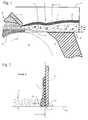
- Figure 1 is a partial view of a Sheet formation system shown in longitudinal section.
- On on the left is the nozzle area of the Headbox 1 with the lower lip 2 and the aperture 3 shown above.
- the Nozzle gap between the aperture 3 and the lower lip 2 the stock suspension is pushed through and hits in Beam impact point 6 on the sieve 10 below on.
- the screen 10 runs over a breast roll 12 a horizontally running sieve table 11.
- over the fabric suspension layer is characterized by a variety of Arrows the secondary flow 5, which is in this Area builds up, shown.
- the Figure the format label 9 attached to the side his wall area over a dried one Fabric area 7 and a wet area underneath 8 has.
- FIG. 2 The cross section A indicated in FIG. 1 is in FIG Figure 2 shown.
- This Figure 2 shows a section through the sieve 10 below, the format label 9, that is adjusted at a distance 14 from the running sieve 10 is.
- Material suspension layer 4 can be seen that the Side of the format label through the secondary flow 5 builds up and shows the tendency on the side wall of the Crawl upwards.
- This tendency of the current to creep up reduced This happens because of the gap 14 a derivative of the pressure pulse that normally runs against the format label 9 and is reflected there is avoided.
- the pressure pulse respectively a substantial part of the pressure pulse can be due to this Escape way between sieve 10 and 9 format label.
- Figure 3 shows the Area of Figure 1 in plan view. Going from above the nozzle area of the headbox 1 can be seen, which has a side wall 15 on which the inventive format label 9 with a Adjustment device 20 is attached.
- the format label 9 is in this example of two connected Segments 9.1 and 9.2 built up, each over one relatively thick-walled main area and a thinner one and thus have elastic transition region 26.
- the thick-walled main areas themselves have side arms 9.3 and 9.4 that again in the machine direction on adjusting rods 16.1 and 16.2 are attached.
- Adjustment rods result in elastic deformation the format label in the area of the thinner version (lower section modulus).
- the format label moves slightly to the direction of the paper web and can thus be used for the undisturbed flow of the Provide material suspension necessary space, without changing the suspension height.
- This format label is dashed by lines 17 shown.
- This format label can preferably be made from Made of plastic or stainless steel become.
- the elastic regions 26 can Gain elasticity by weakening the Material thickness is generated in this area 26.
- Figure 4 shows a side view of this Embodiment of a format label according to the invention, the longitudinal adjustment of the format label over the Adjustment rods 16.1 and 16.2 can be clearly seen.
- the Format label itself is with a screw connection the adjusting screws 18.1, 18.2 and 18.3 on the Side wall 15 of the headbox attached.
- adjusting screws 18.1, 18.2 and 18.3 can be the angle of the format label to Sieve level can be set (swivel angle 24).
- the Adjusting screw 19 the distance of the format label 9 from sieve 10 below it can be adjusted (Distance adjustment 25).
- Gap 14 between format label 9 and sieve 10 in adjust in any way, whereby by the Angle adjustment also different gap heights 14 over the length of the format label can. Furthermore, 16.1 and 16.2 the bend of the format label in Machine direction set in the desired way become.
- the section A-A of Figure 4 is in Figure 5, using the same reference numerals, shown.
- one format label according to the invention compared to the stand technology a significant reduction in the edge waves reached at the beginning of the sheet formation system and thus produces an overall improved paper quality become.
Abstract
Description
Die Erfindung betrifft ein Blattbildungssystem einer
Langsieb-Papiermaschine oder Langsieb-Kartonmaschine
gemäß dem Oberbegriff des Anspruches 1 und ein
Verfahren zur Reduktion von Randwellen gemäß dem
Oberbegriff des Anspruches 9.The invention relates to a sheet formation system
Fourdrinier paper machine or Fourdrinier paperboard machine
according to the preamble of
Die Blattbildungssysteme von Langsiebmaschinen zeichnen sich durch ein endloses Sieb zur Bildung von Papierbahnen oder Kartonbahnen aus, welches über eine offene, flache Tischfläche verläuft. Ein stark mit Wasser verdünnter Papierfaserstoff, die Faserstoffsuspension, wird einem Stoffauflauf zugegeben, der mit einer maschinenbreit verlaufenden Düse einen maschinenbreiten Stoffsuspensionsstrahl erzeugt und diesen auf das laufende Sieb aufgibt. Anschließend wird das wässrige Medium durch das Sieb entwässert und es entsteht eine Faserstoffbahn, die im weiteren Verlauf der Maschine zur fertigen Papier- oder Kartonbahn weiterverarbeitet wird.Draw the sheet forming systems of Fourdrinier machines through an endless sieve to form Paper webs or cardboard webs, which over a open, flat table surface. A strong with Water-diluted paper pulp, the Fibrous suspension, becomes a headbox admitted, the one with a machine width Nozzle a machine-wide stock suspension jet generated and puts this on the running sieve. The aqueous medium is then passed through the sieve dewatered and there is a fibrous web, which in further course of the machine to the finished paper or Cardboard web is processed.
Nach dem Auftreffpunkt des Stoffsuspensionsstrahles auf das Sieb zeigt die Stoffsuspension an den Rändern des Siebes die Tendenz seitlich abzulaufen. Aus diesem Grunde werden im Randbereich der Siebe im Anschluß an die Düse des Stoffauflaufes sogenannte Formatschilde angebracht, die ein seitliches Verlaufen der Stoffsuspension und damit eine Verdünnung der letztendlich entstehenden Papierbahn in diesem Bereich verhindern soll. After the point of impact of the fabric suspension jet the sieve shows the material suspension at the edges of the Siebes the tendency to run sideways. For this Basically in the border area of the sieves after the nozzle of the headbox so-called format plates attached, the lateral run of the Stock suspension and thus a dilution of ultimately emerging paper web in this area should prevent.
Ein derartiges Formatschild ist beispielsweise aus der Deutschen Offenlegungsschrift DE 43 34 641 A1 bekannt, deren Offenbarungsgehalt hiermit vollumfänglich in diese Anmeldung einbezogen wird. Die Aufgabe dieser dort dargestellten Erfindung besteht darin, eine ständige Anhäufung von Faserschichten, die sich in den Randbereichen der fließenden Papierstoffsuspension durch Antrocknung bilden und dann verbundweise in die frische Faserstoffsuspension abblättern, zu vermeiden. Hierfür wird vorgeschlagen, im Bereich der Formatschilde Sprühfontänen vorzusehen, die die Oberflächen der Formatschilde mit einem fließenden Wasserfilm überziehen, so daß eine derartige Antrocknung von Faserstoffanhäufungen vermieden wird. Das Formatschild selbst besteht aus einer flachen Leiste, die durch Hohlprofile in ihrer Richtungsstabilität versteift wird und deren Ausrichtung exakt in Maschinenrichtung zeigt.Such a format label is for example from the German published application DE 43 34 641 A1 known, the content of which is hereby fully disclosed in this registration is included. The task of this invention shown there is a constant accumulation of fiber layers, which can be found in the Edge areas of the flowing pulp suspension by drying and then bonded into the peel fresh fiber suspension, to avoid. For this it is proposed in the area of Spray spray fountain format plates to provide the Surfaces of the format plates with a flowing Cover water film so that such Drying of fiber accumulations is avoided. The format label itself consists of a flat one Ledge by hollow profiles in their Directional stability is stiffened and their Alignment points exactly in the machine direction.
Ein wesentliches Problem dieser bekannten Formatschilder im Blattbildungssystem besteht darin, daß sich im Bereich der Randgrenzschichten der vorbeifließenden Stoffsuspension Sekundärströmungen bilden, die zu Randwellen in der Stoffsuspension führen, die in Richtung Maschinenmitte verlaufen.A major problem with this known Format signs in the sheet formation system consist of that in the area of the marginal boundary layers flowing material suspension secondary flows form that lead to edge waves in the stock suspension lead towards the center of the machine.
Es ist die Aufgabe der Erfindung, das bekannte Blattbildungssystem einer Langsiebmaschine, insbesondere die Formatschilde des Blattbildungssystems dahingehend weiterzuentwickeln, daß die Bildung von Randwellen verringert, beziehungsweise soweit wie möglich vermieden wird. It is the object of the invention, the known Sheet forming system of a Fourdrinier machine, especially the format plates of the sheet formation system to develop further in such a way that the formation of Edge waves reduced, or as far as is avoided as possible.
Weiterhin ist es Aufgabe der Erfindung, ein Verfahren zur Reduktion von Randwellen bei einem Blattbildungssystem einer Papier- oder Kartonmaschine im Bereich der Stoffsuspensionsaufgabe zu beschreiben.It is also an object of the invention to provide a method to reduce edge waves in a Sheet formation system of a paper or board machine to be described in the area of the stock suspension task.
Die erste Aufgabe zur Verbesserung des
Blattbildungssystems wird durch die Merkmale des
Anspruches 1 gelöst. Die zweite Aufgabe zur
Beschreibung eines Verfahrens zur Reduktion von
Randwellen wird durch die Merkmale des Anspruches 9
gelöst.The first task to improve the
Sheet formation system is characterized by the characteristics of the
Die Erfinder haben folgendes erkannt:The inventors recognized the following:
Die Randproblematik in Blattbildungssystem ist ein Problem an der Schnittstelle zwischen Stoffauflauf und Siebpartie. Sie umfaßt die Führung des Freistrahles und die damit verbundenen Reflexionswellen sowie einen Teil der Formatbegrenzung bei der Blattbildung. Aufgrund der Verbesserung der Querprofile der Papierbahn durch die neueren Entwicklungen im Bereich des Stoffauflaufes, die eine sektionierte Stoffdichteregelung zulassen, wirken sich Randprobleme deutlich negativer aus als bisher. Die Ursachen für diese Randwellen oder Reflexionswellen können verschiedene Ursachen haben.The marginal problem in the sheet formation system is one Problem at the interface between headbox and Wire section. It includes the guidance of the free jet and the associated reflection waves and a part the format limit for sheet formation. Due to the Improvement of the transverse profiles of the paper web through the recent developments in the field of headbox, which allow a sectioned material density regulation, marginal problems have a significantly more negative effect than so far. The causes of these edge waves or Reflection waves can have different causes.
Generell entstehen die Randwellen durch Randeffekte, welche sich in Form von bogenförmigen nach oben am Formatschild hinziehenden Sekundärströmungen äußern. Durch die großen benetzten Flächen wird die Strömung im Randbereich erheblich abgebremst und nimmt aufgrund der Kontinuitätsbedingungen einen größeren Raum in Anspruch. Auf diese Weise versperrt die langsamere Randströmung der Hauptströmung, welche am Düsenaustritt annähernd mit Auslaufbreite austritt, auf der Länge des Formatschildes in zunehmenden Maße die gewünschte Fließrichtung. Die Folge ist zwangsläufig eine örtliche Strahlablenkung zur Maschinenmitte hin, die als Reflexionswelle in Erscheinung tritt.Generally the edge waves are caused by edge effects, which is in the form of an arc at the top Express the format sign of the secondary currents. Due to the large wetted areas, the flow in the Edge area braked considerably and decreases due to the Continuity conditions a larger space in Claim. This way, the slower blocks Edge flow of the main flow, which emerges at the nozzle outlet approximately with outlet width, on the length of the Format label increasingly the desired Flow direction. The consequence is necessarily a local one Beam deflection towards the center of the machine, which as Reflection wave appears.
Von diesem Problem sind besonders langsam laufende Maschinen betroffen, die mit großen Spaltöffnungen betrieben werden. Die Reflexionswellen haben hier genug Zeit, sich auf dem Langsieb in den produktionsrelevanten Bereich der Bahn auszubreiten. Bei schnellen Maschinen sind die verschiedenen Effekte etwas schwächer ausgebildet, aber prinzipiell genauso vorhanden.This problem is particularly slow-moving Machines affected with large stomata operate. The reflection waves have enough here Time to sit on the Fourdrinier in the to expand the production-relevant area of the railway. The different effects are with fast machines a little weaker, but basically the same available.
Die Sekundärströmungen können durch verschiedene Effekte entstehen:The secondary flows can be different Effects arise:
Aus konstruktiven Gründen muß die Blende mit einem gewissen Untermaß gefertigt werden, wodurch ein Spalt zwischen Blende und Formatschild entsteht. Dieser sollte idealerweise ca. 0,15 mm betragen, jedoch 0,25 mm nicht überschreiten. Die Nut der Blendenabdichtung kann nicht bis zur Blendenspitze geführt werden. Eine Selbstabdichtung in diesem Bereich durch Fasern, insbesondere bei schnelleren Maschinen, ist durch den dort herrschenden hohen Druck erschwert. Neben der Sekundärströmung am Formatschild können Probleme wie Spritzen, Verschmutzungen der Siebpartie und Zopfbildung auftreten. Dies kann zu erheblichen Störungen führen, insbesondere wenn der Spalt, beispielsweise durch eine nicht mittig zentrierte Blendenposition, zu groß ausfällt. For design reasons, the bezel must have a certain undersize, which creates a gap between the cover and the format label. This should ideally be about 0.15 mm, but 0.25 mm do not exceed. The groove of the panel seal cannot be brought up to the tip of the panel. A Self-sealing in this area by fibers, especially with faster machines, is due to the prevailing high pressure there difficult. In addition to the Secondary flow on the format label can cause problems such as Spraying, contamination of the wire section and Braids appear. This can be significant Cause disturbances, especially if the gap, for example, by a not centered Aperture position, too large.
Eine andere Möglichkeit der Entstehung von Sekundärströmungen kann durch die Wandreibung bedingt sein. Durch die Wandreibung im Stoffauflauf und am Formatschild entsteht eine Grenzschicht, deren Strömungsgeschwindigkeit gegenüber der Strömungsgeschwindigkeit der zentralen Hauptströmung verringert ist. Ohne Formatschild hätte der Strahl das Bestreben sich seitlich auszudehnen und das durch die langsamere Strömungsgeschwindigkeit benötigte größere Volumen zu schaffen. Da dies durch die Formatbegrenzung verhindert wird, baut sich am Formatschild bogenförmig nach oben verlaufend eine Sekundärströmung aus.Another way of creating Secondary flows can be caused by wall friction be. Due to the wall friction in the headbox and on Format label creates a boundary layer, the Flow velocity versus Flow rate of the central main flow is reduced. Without a format label, the beam would have it Strive to expand sideways and through that slower flow speeds required larger ones To create volume. As this is due to the format limitation is prevented, builds an arc on the format label a secondary flow.
Eine weitere Möglichkeit der Entstehung von Sekundärströmungen besteht darin, daß am Strahlauftreffpunkt der Strahl durch die Richtungsänderung am Rand einen in der Regel starken Impuls in Querrichtung erhält, da der Strahl das Bestreben hat sich zur Seite hin auszuweiten. Der Querimpuls führt zu einer zusätzlichen, bogenförmigen Sekundärströmung am Formatschild. Dieser Effekt ist stark vom Auftreffwinkel abhängig, welcher sich sehr individuell aus der Geometrie von Siebpartie und Stoffauflaufposition ergibt.Another way of creating Secondary flows is that on Beam impact point the beam through the Change of direction at the edge is usually a strong one Receives momentum in the transverse direction because the beam The effort has to expand to the side. Of the Cross pulse leads to an additional, arcuate Secondary flow on the format label. This effect is strongly depends on the angle of incidence, which is very different individually from the geometry of the wire section and Headbox position results.
Eine andere Möglichkeit zur Entstehung von Sekundärströmungen kann durch die Siebschüttelung gegeben sein. Durch die Siebschüttelung werden der Stoffsuspension Geschwindigkeitskomponenten in Querrichtung aufgeprägt, wobei durch eine Formatbegrenzung die hier entstehenden Impulse reflektiert werden und in Form einer Randwelle zur Bahnmitte hin verlaufen. Another way to create Secondary flows can be caused by shaking the sieve be given. By shaking the sieve Stock suspension speed components in Imprinted transverse direction, with a Format limitation the impulses arising here be reflected and in the form of an edge wave Run in the middle of the web.
Das wesentliche Element der Erfindung besteht darin, daß die Erfinder erkannt haben, daß die Reflexionswellen beziehungsweise Randwellen reduziert werden können, wenn der Sekundärströmung Raum für eine seitliche Ausdehnung gegeben wird.The essential element of the invention is that the inventors recognized that the Reflection waves or edge waves reduced can be if the secondary flow has room for one lateral expansion is given.
Dies ist bei den bekannten, nicht flexiblen Formatschilden möglich, indem zwischen Sieb und Formschild je nach Bedarf ein Spalt eingestellt wird, durch den ein wesentlicher Teil des Impulses seitlich "entlassen" wird. Hierdurch reduziert sich die Randwelle wesentlich. Allerdings muß das Aufbauen von Stoff in diesem Bereich durch Spritzrohre vermieden werden. Eine Lösung dieses dann auftretenden Problems ist in der oben zitierten DE 43 34 641 A1 beschrieben worden.This is the case with the known, not flexible Format labels possible by placing between sieve and Shape a gap is set as required, through which an essential part of the impulse is from the side is "released". This reduces the Edge wave essential. However, building Avoid spray fabric in this area become. A solution to this problem that then arises is described in DE 43 34 641 A1 cited above been.
Eine weitere Möglichkeit besteht darin, der ungewünschten Sekundärströmung durch die Formatschildkontur Raum zu geben und damit die Hauptströmung nicht einzuengen beziehungsweise nicht zur Maschinenmitte hin umzulenken. Dies kann beispielsweise durch ein verstellbares Formatschild realisiert werden. Mit dieser Ausführung kann die Strömung schon kurz nach Austritt aus der Düse beeinflußt werden. Die Sekundärströmungen, welche sich bisher bogenförmig nach oben am Formatschild ausgebildet haben, werden seitlich abgeführt, Reflexionswellen werden vermindert beziehungsweise gezielt näher an den Rand gelenkt, ohne daß das Ziel der Formatbegrenzung aufgegeben wird. Hierbei muß die Verstellung des Formatschildes derart erfolgen, daß mit zunehmender Entfernung vom Stoffauflauf eine Veränderung, vorzugsweise eine Verbreiterung der für die Stoffsuspension zur Verfügung stehenden Fläche entsteht.Another option is to use the unwanted secondary flow through the To give space to the format label contour and thus the Main flow not to narrow or not to redirect towards the center of the machine. This can for example with an adjustable format label will be realized. With this version, the Flow shortly after exiting the nozzle to be influenced. The secondary flows, which are previously arched upwards on the format label trained, are discharged laterally, Reflection waves are reduced respectively purposefully steered closer to the edge without the goal the format limit is abandoned. Here, the Adjust the format label so that with increasing distance from the headbox Change, preferably a broadening of for the area available for the stock suspension arises.
Ein derartiges neues Formatschild kann mehrteilig, vorzugsweise zweiteilig ausgeführt werden, wobei ab dem Ende des Tischbleches die Formatbegrenzung aus einem durch Spannelemente gezielt verbiegbarem Bauelement, vorzugsweise einem Kunststoffelement, besteht. Durch die maximale Einstellbarkeit auch senkrecht zur Sieboberfläche kann das Formatschild sehr dicht an das Sieb (vorzugsweise ca. 0,5 mm) gestellt werden.Such a new format label can consist of several parts, preferably be carried out in two parts, from The format limit from one end of the table plate component that can be specifically bent by clamping elements, preferably a plastic element. By the maximum adjustability also perpendicular to Sieve surface can the format label very close to that Sieve (preferably about 0.5 mm) are placed.
Gemäß dem Grundgedanken der Erfindung und zur Lösung der Aufgabe wird also vorgeschlagen, ein bekanntes Blattbildungssystem einer Langsieb-Papiermaschine oder Langsieb-Kartonmaschine mit einem Stoffauflauf, mindestens einem umlaufenden Sieb und mindestens zwei, jeweils im Randbereich des Siebes angebrachten Formatschilden dahingehend weiterzuentwickeln, daß die Seitenschilde derart ausgebildet oder befestigt sind, daß der lichte Abstand der Seitenschilde zumindest über einen wesentlichen Teil ihrer Länge in Maschinenrichtung zunehmen kann.According to the basic idea of the invention and to the solution the task is therefore proposed, a known one Sheet forming system of a fourdrinier paper machine or Fourdrinier board machine with a headbox, at least one rotating sieve and at least two, attached to the edge of the sieve Further develop format signs in such a way that the Side shields are designed or attached in such a way that the clear distance of the side shields at least over a substantial part of their length in Machine direction can increase.
Zusätzlich kann es vorteilhaft sein, die Seitenschilde zumindest streckenweise in Maschinenrichtung gesehen elastisch auszubilden. Die elastische Ausbildung des Formatschildes kann beispielsweise durch senkrecht zur Siebebene verlaufende Schwächung der Materialstärke des Formatschildes oder durch einen streckenweisen Ersatz des Materials durch ein besonders elastisches Material wie zum Beispiel Kunststoff oder Gummi erreicht werden. Eine Beweglichkeit des Formatschildes kann auch erreicht werden, wenn es mit mindestens einem Gelenk versehen wird, dessen Achse im wesentlichen senkrecht oder auch leicht geneigt zur Siebebene steht.In addition, the side shields can be advantageous seen at least in sections in the machine direction train elastic. The elastic training of the Format label can for example by perpendicular to Weakening of the material thickness of the Format label or by a replacement in places of the material through a particularly elastic material such as plastic or rubber. The format label can also move can be achieved if it has at least one joint is provided, the axis of which is substantially perpendicular or is also slightly inclined to the sieve level.
Eine andere weiterführende Ausbildung kann darin bestehen, daß an den Seitenschilden jeweils mindestens eine Vorrichtung zu Verformung der Seitenschilde zumindest in Maschinenrichtung vorgesehen ist. Diese Ausführungsform kann dadurch weiterentwickelt werden, daß mindestens eine der Vorrichtungen zur Verformung der Seitenschilde eine Zug- und/oder Druckkraft mit zumindest einer Richtungskomponente quer zur Maschinenrichtung ausübt und/oder daß mindestens eine der Vorrichtungen zur Verformung der Formatschilde an einem seitlich am Formatschild angeordneten Hebelarm angreift und eine Zug- und/oder Druckkraft mit zumindest einer Richtungskomponente in Maschinenrichtung ausübt.Another advanced training can be included exist that at least on the side shields a device for deforming the side shields is provided at least in the machine direction. This Embodiment can be further developed by that at least one of the devices for deformation the side shields with a tensile and / or compressive force at least one directional component transverse to Exercises machine direction and / or that at least one of the devices for deforming the format plates a lever arm arranged on the side of the format label attacks and a tensile and / or compressive force with at least one directional component in Machine direction.
Gemäß dem Erfindungsgedanken wird auch ein Verfahren zur Reduktion von Randwellen bei einem Blattbildungssystem einer Langsieb-Papiermaschine oder Langsieb-Kartonmaschine im Bereich der Stoffsuspensionsaufgabe auf ein umlaufendes Sieb vorgeschlagen, bei dem zur Randbegrenzung des sich bildenden Blattes eine mechanische Seitenbegrenzung benutzt wird, wobei im Randbereich der Blattbildung die für die Stoffsuspension zur Verfügung stehende Fläche in Maschinenrichtung zunehmend, kontinuierlich verändert, vorzugsweise verbreitert wird.According to the inventive concept, a method is also used to reduce edge waves in a Sheet forming system of a fourdrinier paper machine or Fourdrinier board machine in the field of Material suspension application on a rotating sieve proposed, in order to limit the sheet forming a mechanical side boundary is used, the area available for the stock suspension increasing in the machine direction, continuously changed, preferably widened.
In einer Weiterbildung dieses erfindungsgemäßen Verfahren wird die Vergrößerung der Fläche im wesentlichen entsprechend den Regeln der Kontinuitätsgleichung für inkompressible Flüssigkeiten, nach Maßgabe der sich verändernden Fließgeschwindigkeit des Randbereiches vergrößert, um die Schichthöhe der Stoffsuspension im Randbereich konstant zu halten.In a development of this The process of enlarging the area in essentially according to the rules of Continuity equation for incompressible liquids, according to the changing flow rate of the edge area enlarged by the layer height of the Keep material suspension constant in the edge area.
Es versteht sich, daß die vorstehend genannten und nachstehend noch zu erläuternden Merkmale der Erfindung nicht nur in der jeweils angegebenen Kombination, sondern auch in anderen Kombinationen oder in Alleinstellung verwendbar sind, ohne den Rahmen der Erfindung zu verlassen.It is understood that the above and Features of the invention to be explained below not only in the specified combination, but also in other combinations or in USP can be used without the scope of Leaving invention.
Weitere Merkmale und Vorteile der Erfindung ergeben sich aus der nachfolgenden Beschreibung eines bevorzugten Ausführungsbeispieles unter Bezugnahme auf die Zeichnungen.Further features and advantages of the invention result from the following description of a preferred embodiment with reference to the painting.
Die Erfindung soll nun näher anhand eines Ausführungsbeispieles und den Zeichnungen näher erläutert werden.The invention will now be described in more detail using a Embodiment and the drawings closer are explained.
Es zeigen:
- Figur 1:
- Längsschnitt im Bereich des Strahlauftreffpunktes des Blattbildungsbereiches;
- Figur 2:
- Schnitt A
aus Figur 1; - Figur 3:
- Draufsicht auf ein erfindungsgemäßes Formatschild;
- Figur 4:
- Seitenansicht des erfindungsgemäßen Formatschildes;
- Figur 5:
- Schnitt A-A aus Figur 4.
- Figure 1:
- Longitudinal section in the area of the beam impact point of the sheet formation area;
- Figure 2:
- Section A from Figure 1;
- Figure 3:
- Top view of a format label according to the invention;
- Figure 4:
- Side view of the format label according to the invention;
- Figure 5:
- Section AA from FIG. 4.
In der Figur 1 ist eine Teilansicht eines
Blattbildungsystems im Längsschnitt dargestellt. Auf
der linken Seite ist der Düsenbereich des
Stoffauflaufes 1 mit der Unterlippe 2 und der
darüberbefindlichen Blende 3 gezeigt. Durch den
Düsenspalt zwischen der Blende 3 und der Unterlippe 2
wird die Stoffsuspension hindurchgedrückt und trifft im
Strahlauftreffpunkt 6 auf das darunterlaufende Sieb 10
auf. Das Sieb 10 verläuft über eine Brustwalze 12 über
einen waagrecht verlaufenden Siebtisch 11 hinweg. Über
der Stoffsuspensionsschicht ist durch eine Vielzahl von
Pfeilen die Sekundärströmung 5, die sich in diesem
Bereich aufbaut, dargestellt. Zusätzlich zeigt die
Figur das seitlich angebrachte Formatschild 9, das an
seinem Wandbereich über einen angetrockneten
Stoffbereich 7 und darunterliegend einen nassen Bereich
8 verfügt.In Figure 1 is a partial view of a
Sheet formation system shown in longitudinal section. On
on the left is the nozzle area of the
Der in der Figur 1 angedeutete Querschnitt A ist in der
Figur 2 dargestellt. Diese Figur 2 zeigt einen Schnitt
durch das untenliegende Sieb 10, das Formatschild 9,
das mit einem Abstand 14 vom laufenden Sieb 10 justiert
ist. Links neben dem Formatschild ist die
Stoffsuspensionsschicht 4 zu erkennen, die sich an der
Seite des Formatschildes durch die Sekundärströmung 5
aufbaut und die Tendenz zeigt, an der Seitenwand des
Formatschildes nach oben zu kriechen. Durch eine
entsprechende Justierung des Formatschildes 9 wird
diese Tendenz der Strömung nach oben zu kriechen
reduziert. Dies geschieht dadurch, daß durch den Spalt
14 eine Ableitung des Druckimpulses, der normalerweise
gegen das Formatschild 9 läuft und dort reflektiert
wird, vermieden wird. Der Druckimpuls, beziehungsweise
ein wesentlicher Teil des Druckimpulses, kann auf diese
Weise zwischen Sieb 10 und Formatschild 9 entweichen. The cross section A indicated in FIG. 1 is in FIG
Figure 2 shown. This Figure 2 shows a section
through the
Eine weitere Verbesserung zur Reduktion der
Sekundärströmung und damit der entstehenden Randwellen
ist in der Figur 3 dargestellt. Figur 3 zeigt den
Bereich von Figur 1 in der Draufsicht. Von oben kommend
ist der Düsenbereich des Stoffauflaufes 1 zu erkennen,
der über eine Seitenwand 15 verfügt, an der das
erfindungsgemäße Formatschild 9 mit einer
Justiervorrichtung 20 befestigt ist. Das Formatschild 9
ist in diesem Beispiel aus zwei zusammenhängenden
Segmenten 9.1 und 9.2 aufgebaut, die über jeweils einen
relativ dickwandigen Hauptbereich und einen dünneren
und damit elastischen Übergangsbereich 26 verfügen. In
der durchgehend gezeichneten Darstellung ist das
Formatschild im wesentlichen geradlinig ausgerichtet
dargestellt. Die dickwandigen Hauptbereiche selbst
verfügen über seitliche Ausleger 9.3 und 9.4, die
wiederum in Maschinenrichtung an Justierstangen 16.1
und 16.2 befestigt sind.Another improvement to reduce the
Secondary flow and the resulting edge waves
is shown in Figure 3. Figure 3 shows the
Area of Figure 1 in plan view. Coming from above
the nozzle area of the
Durch eine entsprechende Längenveränderung der Justierstangen ergibt sich eine elastische Verformung des Formatschildes im Bereich der dünneren Ausführung (niedrigerer Widerstandsmoment). Das Formatschild bewegt sich geringfügig zur Laufrichtung der Papierbahn und kann so den für den ungestörten Fluß der Stoffsuspension notwendigen Raum zur Verfügung stellen, ohne die Suspensionshöhe zu verändern.By changing the length accordingly Adjustment rods result in elastic deformation the format label in the area of the thinner version (lower section modulus). The format label moves slightly to the direction of the paper web and can thus be used for the undisturbed flow of the Provide material suspension necessary space, without changing the suspension height.
Eine mögliche, aber übertrieben dargestellte Frontlinie
des Formatschildes ist gestrichelt durch die Linien 17
dargestellt. Vorzugsweise kann dieses Formatschild aus
Kunststoff oder nicht-rostenden Stählen hergestellt
werden. Hierbei können die elastischen Bereiche 26 an
Elastizität gewinnen, indem eine Schwächung der
Materialstärke in diesem Bereich 26 erzeugt wird.A possible, but exaggerated front line
the format label is dashed by
Zur Verdeutlichung ist in der Figur 3 links unten eine
Lupenaufnahme solch einer beispielhaften Schwächung des
Bereiches 26 dargestellt. Diese Schwächung der
Materialstärke bewirkt eine Elastizität des Materials
und Beweglichkeit des Formatschildes um eine Achse
senkrecht zur Siebebene, durch die das Formatschild in
gewünschter Weise ausgerichtet werden kann. Die
Ausrichtung kann dabei so erfolgen, daß die
stoffsuspensionsberührte Ebene des Formatschildes, wie
durch die beidseitigen, gekrümmten Pfeile 27
angedeutet, einen Winkel zu beiden Seiten der
Sieblaufrichtung annehmen kann. In besonderen Fällen
kann es sogar vorteilhaft sein, daß diese Winkel im
stromaufwärtigen Teil des Formatschildes 9.1 von
Mittellinie des Siebes weg weisen und im
stromabwärtigen Teil 9.2 auf die Mittellinie des Siebes
zu weisen oder umgekehrt.For clarification, there is one in the bottom left of FIG
Magnifying glass of such an exemplary weakening of the
Die Figur 4 zeigt eine Seitenansicht dieser
Ausführungsform eines erfindungsgemäßen Formatschildes,
wobei die Längsjustierung des Formatschildes über die
Justierstangen 16.1 und 16.2 gut zu erkennen ist. Das
Formatschild selbst ist über eine Schraubverbindung mit
den Justierschrauben 18.1, 18.2 und 18.3 an der
Seitenwand 15 des Stoffauflaufes befestigt. Durch eine
Verstellung einer oder beider Justierschrauben 18.1,
18.2 und 18.3 kann der Winkel des Formatschildes zur
Siebebene eingestellt werden (Schwenkwinkel 24).
Zusätzlich zu dieser Justiermöglichkeit kann über die
Justierschraube 19 der Abstand des Formatschildes 9 vom
darunterverlaufenden Sieb 10 eingestellt werden
(Abstandsverstellung 25). Auf diese Weise ist es
möglich, mit der dargestellten Ausführungsform den
Spalt 14 zwischen Formatschild 9 und Sieb 10 in
beliebiger Weise einzujustieren, wobei durch die
Winkelverstellung auch unterschiedliche Spalthöhen 14
über die Länge des Formatschildes bewirkt werden
können. Weiterhin kann über die Stellstangen 16.1 und
16.2 die Biegung des Formatschildes in
Maschinenrichtung in gewünschter Weise eingestellt
werden. Der Schnitt A-A der Figur 4 ist in der Figur 5,
unter Verwendung der gleichen Bezugszeichen,
dargestellt.Figure 4 shows a side view of this
Embodiment of a format label according to the invention,
the longitudinal adjustment of the format label over the
Adjustment rods 16.1 and 16.2 can be clearly seen. The
Format label itself is with a screw connection
the adjusting screws 18.1, 18.2 and 18.3 on the
Somit kann mit der gezeigten Ausführungsform eines erfindungsgemäßen Formatschildes gegenüber dem Stand der Technik eine wesentliche Reduktion der Randwellen am Beginn des Blattbildungssystemes erreicht und damit eine insgesamt verbesserte Papierqualität erzeugt werden. Thus, with the embodiment shown, one format label according to the invention compared to the stand technology a significant reduction in the edge waves reached at the beginning of the sheet formation system and thus produces an overall improved paper quality become.
- 11
- StoffauflaufHeadbox
- 22nd
- Unterlippebottom lip
- 33rd
- Blendecover
- 44th
- StoffsuspensionsschichtFabric suspension layer
- 55
- SekundärströmungSecondary flow
- 66
- Druckimpuls am StrahlauftreffpunktPressure pulse at the jet impact point
- 77
- angetrockneter Stoffbereichdried fabric area
- 88th
- nasser Bereichwet area
- 99
- FormatschildFormat label
- 9.1, 9.29.1, 9.2
- SegmenteSegments
- 9.3, 9.49.3, 9.4
- Auslegerboom
- 1010th
- SiebSieve
- 1111
- SiebtischSieve table
- 1212th
- BrustwalzeBreast roll
- 1414
- Spaltgap
- 1515
- SeitenwandSide wall
- 16.1, 16.216.1, 16.2
- JustierstangenAdjustment rods
- 1717th
- Linieline
- 18.1, 18.2, 18.318.1, 18.2, 18.3
- Justierschrauben zur WinkelverstellungAdjusting screws for Angle adjustment
- 1919th
- Justierschraube zur AbstandsverstellungAdjusting screw for Distance adjustment
- 2020th
- JustiervorrichtungAdjustment device
- 2121
- "entlassener" Druckimpuls"released" pressure pulse
- 2222
- reflektierter Druckimpulsreflected pressure pulse
- 2323
- Dichtungpoetry
- 2424th
- SchwenkwinkelSwivel angle
- 2525th
- AbstandsverstellungDistance adjustment
- 2626
- SchwächungsbereichWeakening area
Claims (11)
dadurch gekennzeichnet, daß
die Formatschilde (9) derart ausgebildet und/oder befestigt sind, daß der lichte Abstand der Formatschilde von der Mittellinie des Siebes zumindest über einen wesentlichen Teil ihrer Länge in Maschinenrichtung einstellbar ist.Sheet forming system of a Fourdrinier paper or Fourdrinier cardboard machine with a headbox (1), at least one peripheral sieve (10) and at least two format plates (9), each in the edge area of the sieve (10), the headbox (1) passing a machine-wide stock suspension jet via a nozzle generated and placed between the format plates (9) on a sieve (10),
characterized in that
the format plates (9) are designed and / or fastened in such a way that the clear distance between the format plates and the center line of the sieve can be adjusted at least over a substantial part of their length in the machine direction.
Applications Claiming Priority (2)
| Application Number | Priority Date | Filing Date | Title |
|---|---|---|---|
| DE19737646 | 1997-08-29 | ||
| DE19737646A DE19737646A1 (en) | 1997-08-29 | 1997-08-29 | Sheet formation system with format labels |
Publications (3)
| Publication Number | Publication Date |
|---|---|
| EP0899376A2 true EP0899376A2 (en) | 1999-03-03 |
| EP0899376A3 EP0899376A3 (en) | 1999-11-17 |
| EP0899376B1 EP0899376B1 (en) | 2003-05-14 |
Family
ID=7840532
Family Applications (1)
| Application Number | Title | Priority Date | Filing Date |
|---|---|---|---|
| EP98114697A Expired - Lifetime EP0899376B1 (en) | 1997-08-29 | 1998-08-05 | Forming section having deckle frame arrangement |
Country Status (3)
| Country | Link |
|---|---|
| US (1) | US6214169B1 (en) |
| EP (1) | EP0899376B1 (en) |
| DE (2) | DE19737646A1 (en) |
Cited By (5)
| Publication number | Priority date | Publication date | Assignee | Title |
|---|---|---|---|---|
| EP1681390A1 (en) * | 2005-01-14 | 2006-07-19 | Vaahto OY | Apparatus in a paper or cardboard machine for confining the pulp flow from the headbox |
| DE102009000502A1 (en) | 2009-01-30 | 2010-08-05 | Voith Patent Gmbh | Sheet formation system for machine for producing fibrous web, particularly paper, cardboard or packing paper web from fiber suspension, has head box and circulating endless sieve, particularly Fourdrinier wire |
| DE102009000497A1 (en) | 2009-01-30 | 2010-08-05 | Voith Patent Gmbh | Sheet formation system for machine for producing fibrous web, particularly paper, cardboard or packing paper web from fiber suspension, has head box and circulating endless sieve, particularly Fourdrinier wire |
| WO2011086231A1 (en) * | 2010-01-15 | 2011-07-21 | Metso Paper, Inc. | Device for a web forming section of a fiber web machine |
| WO2020030352A1 (en) * | 2018-08-06 | 2020-02-13 | Voith Patent Gmbh | Method for reducing edge waves in a sheet-forming system, and sheet-forming system |
Families Citing this family (1)
| Publication number | Priority date | Publication date | Assignee | Title |
|---|---|---|---|---|
| US8236139B1 (en) * | 2008-06-30 | 2012-08-07 | International Paper Company | Apparatus for improving basis weight uniformity with deckle wave control |
Citations (1)
| Publication number | Priority date | Publication date | Assignee | Title |
|---|---|---|---|---|
| DE4334641A1 (en) * | 1992-10-09 | 1994-04-28 | Westvaco Corp | Flushing fountain for the edge limitation device of a paper machine |
Family Cites Families (10)
| Publication number | Priority date | Publication date | Assignee | Title |
|---|---|---|---|---|
| DE500956C (en) * | 1930-07-19 | J M Voith Maschinenfabrik | Fourdrinier paper, cardboard or cardboard machine in which the length of the fabric is delimited by two width-adjustable delimitation strips and by water jets | |
| US1734929A (en) * | 1926-06-28 | 1929-11-05 | Vedder John Warren | Paper-making machine |
| US3150035A (en) * | 1961-12-22 | 1964-09-22 | Nalco Chemical Co | Treatment of fourdrinier wire |
| US3281314A (en) * | 1964-02-21 | 1966-10-25 | Fitchburg Paper | Stock flow apron for a fourdrinier wire |
| US3607624A (en) * | 1969-08-22 | 1971-09-21 | Nekoosa Edwards Paper Co Inc | Self-cleaning deckle rail for papermaking machines |
| FR2128252A1 (en) * | 1971-03-09 | 1972-10-20 | Sogreah | Paper making machine - has guides bordering filtration screen to limit the width of the web |
| DE2549726B2 (en) * | 1975-11-06 | 1980-04-17 | J.M. Voith Gmbh, 7920 Heidenheim | Machine for the production of fiber webs |
| US4738751A (en) * | 1985-12-18 | 1988-04-19 | Appleton Specialty Products, Inc. | Fabric edge support apparatus for fourdrinier paper machine |
| US4968387A (en) * | 1990-01-23 | 1990-11-06 | Westvaco Corporation | Papermachine deckle means |
| JPH03249297A (en) * | 1990-02-26 | 1991-11-07 | Mitsubishi Heavy Ind Ltd | Method for adjusting direction of flow in head box of paper-making machine |
-
1997
- 1997-08-29 DE DE19737646A patent/DE19737646A1/en not_active Withdrawn
-
1998
- 1998-08-05 EP EP98114697A patent/EP0899376B1/en not_active Expired - Lifetime
- 1998-08-05 DE DE59808331T patent/DE59808331D1/en not_active Expired - Lifetime
- 1998-08-27 US US09/141,339 patent/US6214169B1/en not_active Expired - Lifetime
Patent Citations (1)
| Publication number | Priority date | Publication date | Assignee | Title |
|---|---|---|---|---|
| DE4334641A1 (en) * | 1992-10-09 | 1994-04-28 | Westvaco Corp | Flushing fountain for the edge limitation device of a paper machine |
Cited By (10)
| Publication number | Priority date | Publication date | Assignee | Title |
|---|---|---|---|---|
| EP1681390A1 (en) * | 2005-01-14 | 2006-07-19 | Vaahto OY | Apparatus in a paper or cardboard machine for confining the pulp flow from the headbox |
| DE102009000502A1 (en) | 2009-01-30 | 2010-08-05 | Voith Patent Gmbh | Sheet formation system for machine for producing fibrous web, particularly paper, cardboard or packing paper web from fiber suspension, has head box and circulating endless sieve, particularly Fourdrinier wire |
| DE102009000497A1 (en) | 2009-01-30 | 2010-08-05 | Voith Patent Gmbh | Sheet formation system for machine for producing fibrous web, particularly paper, cardboard or packing paper web from fiber suspension, has head box and circulating endless sieve, particularly Fourdrinier wire |
| WO2011086231A1 (en) * | 2010-01-15 | 2011-07-21 | Metso Paper, Inc. | Device for a web forming section of a fiber web machine |
| CN102713056A (en) * | 2010-01-15 | 2012-10-03 | 美卓造纸机械公司 | Device for a web forming section of a fiber web machine |
| EP2524083A1 (en) * | 2010-01-15 | 2012-11-21 | Metso Paper, Inc. | Device for a web forming section of a fiber web machine |
| EP2524083A4 (en) * | 2010-01-15 | 2013-05-29 | Metso Paper Inc | Device for a web forming section of a fiber web machine |
| WO2020030352A1 (en) * | 2018-08-06 | 2020-02-13 | Voith Patent Gmbh | Method for reducing edge waves in a sheet-forming system, and sheet-forming system |
| CN112534097A (en) * | 2018-08-06 | 2021-03-19 | 福伊特专利有限公司 | Method for reducing edge waves in a sheet forming system and sheet forming system |
| CN112534097B (en) * | 2018-08-06 | 2023-04-14 | 福伊特专利有限公司 | Method for reducing edge waves in a sheet forming system and sheet forming system |
Also Published As
| Publication number | Publication date |
|---|---|
| EP0899376A3 (en) | 1999-11-17 |
| US6214169B1 (en) | 2001-04-10 |
| DE19737646A1 (en) | 1999-03-04 |
| DE59808331D1 (en) | 2003-06-18 |
| EP0899376B1 (en) | 2003-05-14 |
Similar Documents
| Publication | Publication Date | Title |
|---|---|---|
| DE3145413C2 (en) | Device for the simultaneous coating of both sides of a moving web | |
| EP0711869B1 (en) | Multi-layer headbox | |
| EP0581051B1 (en) | Multi-layer headbox for a papermaking machine or the like | |
| DE3321406C2 (en) | ||
| DE3630570A1 (en) | METHOD AND DEVICE IN A PAPER MACHINE CYLINDER DRYER USING TWO-SCREEN GUIDE | |
| DE2736644C2 (en) | Headbox | |
| EP0899376B1 (en) | Forming section having deckle frame arrangement | |
| DE3306717C2 (en) | Web forming section of a four-wire section of a paper machine | |
| EP0761874B1 (en) | Device for making multilayer paper or cardboard | |
| EP0608534A1 (en) | Wet press for a papermaking machine | |
| DE1147470B (en) | Device for producing webs of paper, cardboard or the like. | |
| WO1997038163A1 (en) | Device and method for stabilizing a continuous strip of paper in a paper-making machine in the vicinity of a roll | |
| DE4326867A1 (en) | Paper-making fourdrinier section - has water extraction unit on swing axis for controlled setting according to pulp thickness | |
| DE2626262A1 (en) | TWO-EYE FORMER IN A PAPER MACHINE | |
| DE2807894A1 (en) | PAPER MACHINE | |
| DE19823739A1 (en) | Paper or card coating unit which applies fluid or viscous liquid to wet web | |
| DE2825612C2 (en) | Headbox for paper machines | |
| DE4005147A1 (en) | Paper making stock inlet jet - delivers fibre suspension in a stream which opens out without micro-turbulence | |
| DE4403832C2 (en) | Lower lip for a paper machine headbox | |
| DE4336271A1 (en) | Papermaking web blower system - has a barrier in front of jets to fill the space between the web and blower system. | |
| EP4222309A1 (en) | Flow-optimized edge treatment | |
| DE69821805T2 (en) | METHOD FOR THREADING AND DEVICE FOR FINISHING PAPER | |
| DE3226388A1 (en) | Paper machine | |
| DE10142519A1 (en) | Assembly to detach a paper/cardboard web from a roller, to travel to the next workstation, has a blower jet and a guide wall to keep the high speed web taut in its path to the next production stage | |
| DE2210862C3 (en) | Wire section of a web laying machine operating according to the wet process, in particular a paper machine |
Legal Events
| Date | Code | Title | Description |
|---|---|---|---|
| PUAI | Public reference made under article 153(3) epc to a published international application that has entered the european phase |
Free format text: ORIGINAL CODE: 0009012 |
|
| AK | Designated contracting states |
Kind code of ref document: A2 Designated state(s): DE FI SE |
|
| AX | Request for extension of the european patent |
Free format text: AL;LT;LV;MK;RO;SI |
|
| PUAL | Search report despatched |
Free format text: ORIGINAL CODE: 0009013 |
|
| AK | Designated contracting states |
Kind code of ref document: A3 Designated state(s): AT BE CH CY DE DK ES FI FR GB GR IE IT LI LU MC NL PT SE |
|
| AX | Request for extension of the european patent |
Free format text: AL;LT;LV;MK;RO;SI |
|
| RAP1 | Party data changed (applicant data changed or rights of an application transferred) |
Owner name: VOITH SULZER PAPIERTECHNIK PATENT GMBH |
|
| 17P | Request for examination filed |
Effective date: 20000517 |
|
| AKX | Designation fees paid |
Free format text: DE FI SE |
|
| RAP1 | Party data changed (applicant data changed or rights of an application transferred) |
Owner name: VOITH PAPER PATENT GMBH |
|
| 17Q | First examination report despatched |
Effective date: 20020306 |
|
| GRAH | Despatch of communication of intention to grant a patent |
Free format text: ORIGINAL CODE: EPIDOS IGRA |
|
| RTI1 | Title (correction) |
Free format text: FORMING SECTION HAVING DECKLE FRAME ARRANGEMENT |
|
| GRAH | Despatch of communication of intention to grant a patent |
Free format text: ORIGINAL CODE: EPIDOS IGRA |
|
| GRAA | (expected) grant |
Free format text: ORIGINAL CODE: 0009210 |
|
| AK | Designated contracting states |
Designated state(s): DE FI SE |
|
| REF | Corresponds to: |
Ref document number: 59808331 Country of ref document: DE Date of ref document: 20030618 Kind code of ref document: P |
|
| REG | Reference to a national code |
Ref country code: SE Ref legal event code: TRGR |
|
| PLBE | No opposition filed within time limit |
Free format text: ORIGINAL CODE: 0009261 |
|
| STAA | Information on the status of an ep patent application or granted ep patent |
Free format text: STATUS: NO OPPOSITION FILED WITHIN TIME LIMIT |
|
| 26N | No opposition filed |
Effective date: 20040217 |
|
| PGFP | Annual fee paid to national office [announced via postgrant information from national office to epo] |
Ref country code: SE Payment date: 20120821 Year of fee payment: 15 |
|
| REG | Reference to a national code |
Ref country code: SE Ref legal event code: EUG |
|
| PG25 | Lapsed in a contracting state [announced via postgrant information from national office to epo] |
Ref country code: SE Free format text: LAPSE BECAUSE OF NON-PAYMENT OF DUE FEES Effective date: 20130806 |
|
| PGFP | Annual fee paid to national office [announced via postgrant information from national office to epo] |
Ref country code: FI Payment date: 20170822 Year of fee payment: 20 Ref country code: DE Payment date: 20170822 Year of fee payment: 20 |
|
| REG | Reference to a national code |
Ref country code: DE Ref legal event code: R071 Ref document number: 59808331 Country of ref document: DE |