EP0608534A1 - Wet press for a papermaking machine - Google Patents
Wet press for a papermaking machine Download PDFInfo
- Publication number
- EP0608534A1 EP0608534A1 EP93120064A EP93120064A EP0608534A1 EP 0608534 A1 EP0608534 A1 EP 0608534A1 EP 93120064 A EP93120064 A EP 93120064A EP 93120064 A EP93120064 A EP 93120064A EP 0608534 A1 EP0608534 A1 EP 0608534A1
- Authority
- EP
- European Patent Office
- Prior art keywords
- press
- roll
- nip
- paper web
- wet
- Prior art date
- Legal status (The legal status is an assumption and is not a legal conclusion. Google has not performed a legal analysis and makes no representation as to the accuracy of the status listed.)
- Granted
Links
Images


Classifications
-
- D—TEXTILES; PAPER
- D21—PAPER-MAKING; PRODUCTION OF CELLULOSE
- D21F—PAPER-MAKING MACHINES; METHODS OF PRODUCING PAPER THEREON
- D21F3/00—Press section of machines for making continuous webs of paper
- D21F3/02—Wet presses
- D21F3/04—Arrangements thereof
- D21F3/045—Arrangements thereof including at least one extended press nip
-
- D—TEXTILES; PAPER
- D21—PAPER-MAKING; PRODUCTION OF CELLULOSE
- D21F—PAPER-MAKING MACHINES; METHODS OF PRODUCING PAPER THEREON
- D21F3/00—Press section of machines for making continuous webs of paper
- D21F3/02—Wet presses
- D21F3/04—Arrangements thereof
Definitions
- a press of this type has become known from US-A-4,556,451.
- This press comprises four press rolls which form an uninterrupted chain with one another, so that the paper web always wraps around a press roll on a part of its circumference as it passes through the press, and that a total of three press nips are formed.
- the four-roll press mentioned is preceded by a two-roll press which takes over the paper web coming from the wire of the paper machine.
- US-A-2 694 348 describes a press section in which the paper web is first removed from the paper machine screen by means of a felt belt and is passed with this felt belt through a first two-roll press.
- a second felt which also runs through the aforementioned two-roll press, takes over the paper web and guides it through a second two-roll press.
- the paper web is then removed from a third felt belt which passes through the second two-roll press; this third felt belt passes the paper web through a third two-roll press and further through a fourth two-roll press.
- This press section thus has a total of four press nips. Felt tapes are thus simultaneously passed through all press nips with the paper web. Between the individual press nips, the paper web is transported by the felts mentioned, namely on a route on which the felt web bridges a free path length with the paper web located thereon or attached to it.
- wet presses should generally have a high pressing efficiency, take up as little space as possible, especially when viewed in the running direction of the paper web and in the horizontal direction, and they should also have an inexpensive construction.
- the invention is therefore based on the object of designing a wet press according to the preamble of claim 1 in such a way that, with high pressing efficiency and high speeds, a perfect transfer of the narrow transfer strip or the completely wide paper web is ensured that the marking of screens or of borehole patterns reduced by suction rollers in the moist paper web or is avoided, and that the felt wear is reduced.
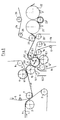
- FIG. 1 A belt-shaped screen 1, which rotates in the direction of the arrow, wraps around a suction roller 2 and a deflection roller 3.
- the screen 1 carries a paper web 4, which is shown in broken lines.
- a first felt 5 can also be seen, which is also designed as an endless loop.
- the felt 5 wraps around a number of guide rollers, of which the guide roller 6, the suction guide roller 7 and the guide roller 8 are shown, and also a press roller 9, which is part of the press.
- Press roll 9 forms with a further press roll 10 a first press point I.
- Press roll 9 is a shoe press roll with a pressure shoe 9. 1 shown only schematically, with which a relatively long press nip is produced, as seen in the direction of wire travel.
- the contact shoe 9.1 is, in a known manner, displaceable in the radial direction relative to a stationary support body, not shown, so that the pressing force acting in the pressing point I can be varied.
- Through the press point I runs a tubular and flexible press jacket sliding over the pressure shoe; its outer surface can have fine recesses (eg blind holes) for temporarily storing water (the recesses are symbolically represented by a dashed line).
- Press roll 10 is followed by a third press roll 11.
- Press roll 11 is adjustably mounted in the sense of double arrow 11 'for the purpose of varying the press force in press nip II.
- Press roller 11 is followed by a fourth press roller 12, which is also a shoe press roller with a pressure shoe 12.1.
- the rollers 11 and 12 together form a third press nip III.
- Press roll 12 is located within the endless loop of a second press felt 14, which in turn is looped around guide rolls 15, 16, 17, etc.
- the flexible press jacket of the press roll 12 can also have fine recesses on its outside, especially if a relatively thin and finely woven press felt 14 is used, the water absorption capacity of which is relatively low.
- Press roll 13 is located within the endless loop of a third press felt 18. This is guided around guide rolls as around guide rolls 19, 20.
- a dryer section is connected to the wet press in the usual way.
- it is a single-tier dryer section.
- This includes a variety drying cylinders 21, 22, a plurality of deflection suction rolls 23, etc., each arranged between two drying cylinders, and a drying wire 24 with guide rolls 25, 26, etc.
- a deflection suction roll 27 At the beginning of the drying section there is a deflection suction roll 27. This serves to remove the paper web 4 from the third press felt 18 to take off.
- scraper 10.1 which is assigned to the press roll 10
- scraper 11.1 which is assigned to the press roll 11
- reject discharge channel 10.2 which is located below the press roll 10.
- the course of the paper web 4 is as follows: The paper web 4 is first removed from the wire 1 by means of the first press felt 5 and the pick-up roller 7. It then hangs at the bottom of the first press felt 5. Together with this, it passes through the first press nip I, then leaves the press felt 5, remains on the circumference of the press roll 10 until it reaches the second press nip II, then remains on the circumference of the press roll 11 until it is reached of the third press nip III and - if necessary - the fourth press nip IV, and is then transferred by means of the deflection suction roll 13 to the third press felt 18, from which it is removed by the deflection suction roll 27 and passed through the dryer section with the dryer wire 24.
- press roll 10 has a relatively soft jacket, while the press roll 11 has a relatively hard coat.
- Press felt 18 is expediently formed from a relatively fine fabric, so that the paper web 4 at the last press nip IV (if there is one) receives relatively little marking by the press felt 18. In other words: the underside of the paper web 4 remains relatively smooth on contact with the press felt 18.
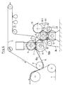
- FIG. 2 The configuration shown in FIG. 2 is similar to that of FIG. 1.
- a part of the wire section with the wire 1, the wire suction roll 2, the deflecting roller 3, and the paper web 4 carried along on the wire 1 can again be seen.
- a first press felt 5 is provided, which passes the paper web 4 through a first Press nip I passes between the rollers 9 and 10.
- Roll 9 is a press roll with a smooth, i.e. closed outer surface. Deviating from this, the outer surface of the roller 9 (for temporarily storing water) can also be provided with fine recesses, e.g. Circumferential grooves.
- the rest of the structure of the press is also very similar to that shown in FIG. 1.
- the fifth press roll 13 is a roll with a closed outer surface.
- the paper web 4 is delivered from the press roll 13 to the drying wire 24, the deflection suction roll 27 ensuring a reliable transfer.
- FIG. 3 The configuration shown in Figure 3 is designed up to the pick-up roller 7 analogous to the two previous configurations. This is followed by an upstream press with a press nip Ia, formed from two press rolls 30 and 31.
- Press roll 30 has a suction zone 30a in order to securely feed the paper web 4 to the press nip Ia to lead.
- Press roller 31 has a suction zone 31.1 in order to safely transfer the paper web 4 onto a second press felt 11 '.
- the subsequent press again comprises five press rolls, namely rolls 9, 10, 11, 12 and 13.
- the roll 9 (with a smooth or grooved surface) is also located in the loop of the felt 11 '. Together with roller 10, it forms a press nip I.
- the rollers 10 and 11 together form a press nip II; the rollers 11 and 12 together form a press nip III; the rollers 11 and 13 together form a fourth press nip IV.
- the roller 12 is located within the loop of a third press felt 17.
- the roller 13 is at the same time a suction deflecting roller and is used to transfer the paper web 4 onto a dryer fabric 18 of the downstream dryer section.
- the dryer section and its elements do not need to be described here, since they basically have the same structure as the dryer sections of the other two configurations.
- the paper web 4 always follows the circumferences of the press rolls involved from the first press nip I to the last press nip IV. It never runs free.
- the second press nip II of this press is formed from a roller with a relatively soft shell - here roller 10 - and from a roller with a hard shell - here roller 11.
- the roller 10 with a soft jacket is again arranged in front of the roller 11 with a hard jacket, as seen in the direction of travel of the paper web 4.
- Roller 12 (with a press jacket which is smooth on the outside or provided with recesses) is in turn a shoe press roller with a shoe 12.1.
- the configuration shown in Figure 4 is the Similar to the first two configurations according to FIGS. 1 and 2, as here too the five-roll press shown is the only press and no two-roll press is connected upstream. However, it goes without saying that this could also be different. Another press could be connected upstream and another press could also be connected downstream.
- This bar 10b is used to open or close the press nip II and to vary the pressing force in the press nip II. Thanks to the movable bar 10b, the press roll 11 need not be adjustable, in contrast to the exemplary embodiments according to FIGS. 1 to 3. In other words: The four press rolls 9 to 12 can all be supported essentially rigidly on a foundation or on a machine frame. This results in an extremely simple and space-saving arrangement of the entire wet press.
- the paper web 4 is removed from the screen 1 by means of the press felt 5 and the pick-up roller 7 and passed through the first press nip I with the felt 5.
- the paper web 4 runs through the second press nip II alone, ie without felt.
- press nip III it is again like with press nip I; here too, paper web 4 and a felt 14 run through it together Press nip.
- press nip IV it is again like with press nip II: the paper web 4 runs alone through this press nip.
- This alternating path - first with felt, then without felt, then again with felt, and finally without felt - is very advantageous. Pressing out with felt allows a relatively intensive dewatering, but has the disadvantage of marking the felt fabric in the moist paper web, while the downstream press nip without felt ensures a smoothing of this previous felt marking.
- a spray tube 13.1 is assigned to the press roller 13. It applies a water spray over the entire width of the roller to the outer surface of the roller 13 just before the press nip IV. This can, if necessary, ensure that the paper web continues to run behind the press nip IV with the roller 13.
- a scraper 13.2 cleans the outer surface of the roller 13.
Landscapes
- Paper (AREA)
Abstract
Description
Die Erfindung betrifft eine Naßpresse für eine Papiermaschine. Auf den Oberbegriff von Anspruch 1 wird verwiesen.The invention relates to a wet press for a paper machine. Reference is made to the preamble of claim 1.
Eine Presse dieser Art ist aus US-A-4 556 451 bekanntgeworden. Diese Presse umfaßt vier Preßwalzen, die eine ununterbrochene Kette miteinander bilden, so daß die Papierbahn beim Durchlaufen der Presse stets eine Preßwalze auf einem Teil von deren Umfang umschlingt, und daß insgesamt drei Preßspalte gebildet werden. Der genannten Vier-Walzen-Presse ist eine Zwei-Walzen-Presse vorgeschaltet, die die vom Sieb der Papiermaschine kommende Papierbahn übernimmt.A press of this type has become known from US-A-4,556,451. This press comprises four press rolls which form an uninterrupted chain with one another, so that the paper web always wraps around a press roll on a part of its circumference as it passes through the press, and that a total of three press nips are formed. The four-roll press mentioned is preceded by a two-roll press which takes over the paper web coming from the wire of the paper machine.
Es ist eine große Anzahl von Pressenpartien der unterschiedlichsten Konfiguration bekanntgeworden. US-A-2 694 348 beschreibt eine Pressenpartie, bei der zunächst die Papierbahn mittels eines Filzbandes vom Papiermaschinensieb abgenommen und mit diesem Filzband durch eine erste Zwei-Walzen-Presse hindurchgeführt wird. Ein zweiter Filz, der ebenfalls durch die genannte Zwei-Walzen-Presse hindurchläuft, übernimmt die Papierbahn und führt sie durch eine zweite Zwei-Walzen-Presse hindurch. Sodann wird die Papierbahn von einem dritten Filzband abgenommen, das durch die zweite Zwei-Walzen-Presse hindurchläuft; dieses dritte Filzband führt die Papierbahn durch eine dritte Zwei-Walzen-Presse hindurch, und weiter durch eine vierte Zwei-Walzen-Presse. Diese Pressenpartie weist somit insgesamt vier Preßspalte auf. Durch sämtliche Preßspalte sind somit gleichzeitig mit der Papierbahn Filzbänder hindurchgeführt. Zwischen den einzelnen Preßspalten wird die Papierbahn von den genannten Filzen transportiert, und zwar auf einer Strecke, auf der die Filzbahn mit der darauf befindlichen oder daran hängenden Papierbahn eine freie Weglänge überbrückt.A large number of press sections of various configurations have become known. US-A-2 694 348 describes a press section in which the paper web is first removed from the paper machine screen by means of a felt belt and is passed with this felt belt through a first two-roll press. A second felt, which also runs through the aforementioned two-roll press, takes over the paper web and guides it through a second two-roll press. The paper web is then removed from a third felt belt which passes through the second two-roll press; this third felt belt passes the paper web through a third two-roll press and further through a fourth two-roll press. This press section thus has a total of four press nips. Felt tapes are thus simultaneously passed through all press nips with the paper web. Between the individual press nips, the paper web is transported by the felts mentioned, namely on a route on which the felt web bridges a free path length with the paper web located thereon or attached to it.
Ganz allgemein wird angestrebt, Naßpressen bzw. ganze Naßpreßpartien den hohen Anforderungen schnell laufender Papiermaschinen anzupassen. Naßpressen sollen allgemein einen hohen Preß-Wirkungsgrad aufweisen, möglichst wenig Raum einnehmen, vor allem in Laufrichtung der Papierbahn und in horizontaler Richtung gesehen, und sie sollen außerdem einen kostengünstigen konstruktiven Aufbau haben.In general, the aim is to adapt wet presses or entire wet press sections to the high requirements of fast-running paper machines. Wet presses should generally have a high pressing efficiency, take up as little space as possible, especially when viewed in the running direction of the paper web and in the horizontal direction, and they should also have an inexpensive construction.
Mit zunehmender Geschwindigkeit moderner Papiermaschinen nehmen jedoch die technischen Probleme zu, so daß immer neue Teilaufgaben zu lösen sind. Derartige Probleme treten z.B. auf beim Anfahren der Papiermaschine nach einem Stillstand, wenn ein schmaler Papierstreifen durch die Pressenpartie hindurchgeführt werden muß. Ferner nimmt mit zunehmender Geschwindigkeit der Papiermaschine die Abrißgefahr der Papierbahn zu. Weiterhin muß man mit zunehmender Geschwindigkeit die Entwässerungsleistung der Pressenpartie steigern, was sich nicht ohne eine Vergrößerung der Zahl der Preßspalte machen läßt. Hierdurch wird jedoch mehr Raum in Laufrichtung der Papiermaschine benötigt. Ein weiteres Problem ist die Markierung der Preßfilze in der noch feuchten Papierbahn. Schließlich steigt mit zunehmender Maschinengeschwindigkeit und mit zunehmenden Liniendrücken in den Preßspalten der Verschleiß der Preßfilze, so daß diese häufiger gegen neue Filze ausgetauscht werden müssen, was natürlich die Kosten hochtreibt.However, with increasing speed of modern paper machines, the technical problems increase, so that new sub-tasks have to be solved. Such problems arise e.g. when starting up the paper machine after a standstill, if a narrow paper strip has to be passed through the press section. Furthermore, the risk of tearing off the paper web increases with increasing speed of the paper machine. Furthermore, the drainage capacity of the press section must be increased with increasing speed, which cannot be done without increasing the number of press nips. However, this requires more space in the direction of the paper machine. Another problem is the marking of the press felts in the still wet paper web. Finally, the wear of the press felts increases with increasing machine speed and with increasing line pressures in the press nips, so that these have to be exchanged more frequently for new felts, which of course drives up the costs.
Alle diese Probleme wurden mit den bekannten Einrichtungen nicht in optimaler Weise gelöst. Der Erfindung liegt daher die Aufgabe zugrunde, eine Naßpresse gemäß dem Oberbegriff von Anspruch 1 derart zu gestalten, daß bei hohem Preßwirkungsgrad und hohen Geschwindigkeiten ein einwandfreies Überführen des schmalen Überführstreifens bzw. der vollständig breiten Papierbahn gewährleistet ist, daß die Markierung von Sieben oder von Bohrlochmustern von Saugwalzen in der feuchten Papierbahn verringert oder vermieden wird, und daß der Filzverschleiß gesenkt wird.All these problems have not been optimally solved with the known devices. The invention is therefore based on the object of designing a wet press according to the preamble of claim 1 in such a way that, with high pressing efficiency and high speeds, a perfect transfer of the narrow transfer strip or the completely wide paper web is ensured that the marking of screens or of borehole patterns reduced by suction rollers in the moist paper web or is avoided, and that the felt wear is reduced.
Diese Aufgabe wird durch die kennzeichnenden Merkmale von Anspruch 1 gelöst.This object is solved by the characterizing features of claim 1.
Die Erfindung ist anhand der Zeichnung näher erläutert. Darin ist im einzelnen folgendes dargestellt:
- Figur 1
- zeigt eine Pressenpartie mit einer Fünf-Walzen-Presse, die zwei Schuh-Preßwalzen enthält.
Figur 2- zeigt eine Pressenpartie mit einer Vier-Walzen-Presse, die eine Schuhpresse aufweist.
Figur 3- zeigt eine Pressenpartie, die u.a. eine Fünf-Walzen-Presse enthält; eine dieser Walzen ist wiederum eine Schuh-Preßwalze.
Figur 4- zeigt eine Pressenpartie mit einer Fünf-Walzen-Presse, die zwei Schuh-Preßwalzen enthält.
- Figure 1
- shows a press section with a five-roll press that contains two shoe press rolls.
- Figure 2
- shows a press section with a four-roll press, which has a shoe press.
- Figure 3
- shows a press section, which includes a five-roll press; one of these rollers is in turn a shoe press roller.
- Figure 4
- shows a press section with a five-roll press that contains two shoe press rolls.
In Figur 1 erkennt man im einzelnen die folgenden Elemente: Ein bandförmiges Sieb 1, das in Pfeilrichtung umläuft, umschlingt eine Saugwalze 2 und eine Umlenkwalze 3. Das Sieb 1 trägt eine Papierbahn 4, die gestrichelt dargestellt ist.The following elements can be seen in detail in FIG. 1: A belt-shaped screen 1, which rotates in the direction of the arrow, wraps around a
Man erkennt weiterhin einen ersten Filz 5, der ebenfalls als endlose Schlaufe ausgebildet ist. Der Filz 5 umschlingt eine Reihe von Leitwalzen, von denen die Leitwalze 6, die Saugleitwalze 7 und die Leitwalze 8 dargestellt sind, ferner eine Preßwalze 9, die Bestandteil der Presse ist.A
Preßwalze 9 bildet mit einer weiteren Preßwalze 10 eine erste Preßstelle I. Preßwalze 9 ist eine Schuh-Preßwalze mit einem hier nur schematisch dargestellten Anpreßschuh 9.1, mit welchem ein in Sieblaufrichtung gesehen relativ langer Preßspalt hergestellt wird. Der Anpreßschuh 9.1 ist, in bekannter Weise, relativ zu einem nicht dargestellten stationären Tragkörper in radialer Richtung verschiebbar, so daß die in der Preßstelle I wirkende Preßkraft variierbar ist. Durch die Preßstelle I läuft ein über den Anpreßschuh gleitender schlauchförmiger und flexibler Preßmantel; dessen Außenfläche kann feine Ausnehmungen (z.B. Sackbohrungen) aufweisen zum vorübergehenden Speichern von Wasser (die Ausnehmungen sind symbolisch dargestellt durch eine gestrichelte Linie). Auf Preßwalze 10 folgt eine dritte Preßwalze 11. Die beiden von der Papierbahn 4 berührten Preßwalzen 10 und 11 bilden miteinander einen filzlosen zweiten Preßspalt II. Preßwalze 11 ist im Sinne des Doppelpfeiles 11' verstellbar gelagert, zum Zwecke des Variierens der Preßkraft im Preßspalt II. Auf Preßwalze 11 folgt eine vierte Preßwalze 12, die ebenfalls eine Schuh-Preßwalze mit einem Anpreßschuh 12.1 ist. Die Walzen 11 und 12 bilden miteinander einen dritten Preßspalt III. Eine fünfte Preßwalze 13, die als Saugpreßwalze ausgebildet ist, bildet mit Preßwalze 11 einen vierten Preßspalt IV. Preßwalze 13 ist im Sinne des Doppelpfeiles 13.1 gegen Preßwalze 11 anstellbar bzw. von dieser abfahrbar, so daß je nach den Betriebsbedingungen Preßspalt IV entfällt.
Preßwalze 12 befindet sich innerhalb der endlosen Schlaufe eines zweiten Preßfilzes 14, der wiederum um Leitwalzen 15, 16, 17 usw. herumgeschlungen ist. Auch der flexible Preßmantel der Preßwalze 12 kann auf seiner Außenseite feine Ausnehmungen aufweisen, insbesondere wenn ein relativ dünner und fein gewobener Preßfilz 14 eingesetzt wird, dessen Wasseraufnahmevermögen relativ gering ist.
Preßwalze 13 befindet sich innerhalb der endlosen Schlaufe eines dritten Preßfilzes 18. Dieser ist um Leitwalzen herumgeführt, wie um die Leitwalzen 19, 20.
An die Naßpresse schließt sich in üblicher Weise eine Trockenpartie an. Im vorliegenden Falle handelt es sich um eine einreihige Trockenpartie. Diese umfaßt eine Vielzahl von Trockenzylindern 21, 22, eine Vielzahl von jeweils zwischen zwei Trockenzylindern angeordneten Umlenksaugwalzen 23 usw., sowie ein Trockensieb 24 mit Leitwalzen 25, 26 usw. Am Anfang der Trockenpartie befindet sich eine Umlenksaugwalze 27. Diese dient dazu, die Papierbahn 4 vom dritten Preßfilz 18 abzunehmen.A dryer section is connected to the wet press in the usual way. In the present case, it is a single-tier dryer section. This includes a
Wie man erkennt, sind weitere Elemente vorhanden, die aber für die Erfindung nicht von primärer Bedeutung sind. Hierzu gehören beispielsweise ein Schaber 10.1, der der Preßwalze 10 zugeordnet ist, ein Schaber 11.1, der der Preßwalze 11 zugeordnet ist, eine Ausschußabführrinne 10.2, die sich unterhalb der Preßwalze 10 befindet.As can be seen, there are other elements, but they are not of primary importance for the invention. These include, for example, a scraper 10.1, which is assigned to the
Wie man sieht, ist der Verlauf der Papierbahn 4 wie folgt: Die Papierbahn 4 wird zunächst mittels des ersten Preßfilzes 5 und der Pick-up-Walze 7 vom Sieb 1 abgenommen. Sie hängt sodann unten am ersten Preßfilz 5. Zusammen mit diesem gelangt sie durch den ersten Preßspalt I, verläßt sodann den Preßfilz 5, verbleibt am Umfang der Preßwalze 10 bis zum Erreichen des zweiten Preßspaltes II, verbleibt sodann am Umfang der Preßwalze 11 bis zum Erreichen des dritten Preßspaltes III und - gegebenenfalls - des vierten Preßspaltes IV, und wird sodann mittels der Umlenksaugwalze 13 auf den dritten Preßfilz 18 überführt, von welchem sie durch die Umlenksaugwalze 27 abgenommen und mit dem Trockensieb 24 durch die Trockenpartie hindurchgeführt wird.As can be seen, the course of the
Wichtig ist hierbei, daß die Papierbahn 4 bei ihrem Durchlauf durch die Naßpresse stets an der Mantelfläche einer der beteiligten Preßwalzen haftet, so daß auf diesem kritischen Abschnitt des Laufes der Papierbahn ein Abriß praktisch unmöglich ist.It is important here that the
Ferner ist von Bedeutung, daß die Preßwalze 10 einen relativ weichen Mantel aufweist, während die Preßwalze 11 einen relativ harten Mantel aufweist. Auch hat sich der Wechsel von dem befilzten Preßspalt I, gebildet aus einer Schuhpresse, zu dem filzlosen Preßspalt II, gebildet aus völlig glatten (geschlossenen) Mantelflächen, und weiter zu dem befilzten Preßspalt III, wiederum aus einer Schuhpresse gebildet, als besonders günstig erwiesen. Preßfilz 18 ist zweckmäßigerweise aus einem relativ feinen Gewebe gebildet, so daß die Papierbahn 4 am letzten Preßspalt IV (falls ein solcher vorhanden ist) relativ wenig Markierung durch den Preßfilz 18 erhält. Mit anderen Worten: Die Unterseite der Papierbahn 4 bleibt beim Kontakt mit dem Preßfilz 18 relativ glatt.It is also important that the
Die in Figur 2 gezeigte Konfiguration ist ähnlich jener von Figur 1 aufgebaut. Man erkennt wieder einen Teil der Siebpartie mit dem Sieb 1, der Siebsaugwalze 2, der Umlenkwalze 3, und die auf dem Sieb 1 mitgeführte, gestrichelt dargestellte Papierbahn 4. Auch hier ist wieder ein erster Preßfilz 5 vorgesehen, der die Papierbahn 4 durch einen ersten Preßspalt I zwischen den Walzen 9 und 10 hindurchführt. Walze 9 ist hierbei eine Preßwalze mit glatter, d.h. geschlossener Mantelfläche. Abweichend hiervon kann die Mantelfläche der Walze 9 (zum vorübergehenden Speichern von Wasser) auch mit feinen Ausnehmungen, z.B. Umfangsrillen, versehen werden. Auch der übrige Aufbau der Presse ist sehr ähnlich jener gemäß Figur 1. Jedoch ist die fünfte Preßwalze 13 eine Walze mit geschlossener Mantelfläche. Die Papierbahn 4 wird von Preßwalze 13 an Trockensieb 24 abgegeben, wobei die Umlenksaugwalze 27 für eine zuverlässige Überführung sorgt.The configuration shown in FIG. 2 is similar to that of FIG. 1. A part of the wire section with the wire 1, the
Die in Figur 3 dargestellte Konfiguration ist bis zur Pick-up-Walze 7 analog den beiden vorausgegangenen Konfigurationen gestaltet. Es folgt sodann eine vorgeschaltete Presse mit einem Preßspalt Ia, gebildet aus zwei Preßwalzen 30 und 31. Preßwalze 30 weist eine Saugzone 30a auf, um die Papierbahn 4 sicher zum Preßspalt Ia zu führen. Preßwalze 31 weist eine Saugzone 31.1 auf, um die Papierbahn 4 sicher auf einen zweiten Preßfilz 11' zu überführen.The configuration shown in Figure 3 is designed up to the pick-up
Wie man sieht, umfaßt die nachfolgende Presse wiederum fünf Preßwalzen, nämlich die Walzen 9, 10, 11, 12 und 13. Die Walze 9 (mit glatter oder gerillter Oberfläche) befindet sich ebenfalls in der Schlaufe des Filzes 11'. Sie bildet zusammen mit Walze 10 einen Preßspalt I. Die Walzen 10 und 11 bilden miteinander einen Preßspalt II; die Walzen 11 und 12 bilden miteinander einen Preßspalt III; die Walzen 11 und 13 bilden miteinander einen vierten Preßspalt IV.As can be seen, the subsequent press again comprises five press rolls, namely rolls 9, 10, 11, 12 and 13. The roll 9 (with a smooth or grooved surface) is also located in the loop of the felt 11 '. Together with
Die Walze 12 befindet sich innerhalb der Schlaufe eines dritten Preßfilzes 17. Die Walze 13 ist zugleich eine Saugumlenkwalze und dient zum Überführen der Papierbahn 4 auf ein Trockensieb 18 der nachgeschalteten Trockenpartie. Die Trockenpartie und ihre Elemente brauchen hier nicht näher beschrieben zu werden, da sie im Grunde denselben Aufbau wie die Trockenpartien der beiden anderen Konfigurationen haben.The
Auch bei dieser erfindungsgemäßen Presse, umfassend die Preßwalzen 9-13, folgt die Papierbahn 4 auf ihrem Verlaufe vom ersten Preßspalt I bis zum letzten Preßspalt IV stets den Umfängen der beteiligten Preßwalzen. Sie läuft somit niemals frei. Auch hier ist der zweite Preßspalt II dieser Presse aus einer Walze mit relativ weichem Mantel - hier Walze 10 - und aus einer Walze mit hartem Mantel - hier Walze 11 - gebildet. Dabei ist die Walze 10 mit weichem Mantel wiederum - in Laufrichtung der Papierbahn 4 gesehen - vor der Walze 11 mit hartem Mantel angeordnet. Walze 12 (mit außen glattem oder mit Ausnehmungen versehenem Preßmantel) ist wiederum eine Schuh-Preßwalze mit einem Schuh 12.1.Also in this press according to the invention, comprising the press rolls 9-13, the
Die in Figur 4 dargestellte Konfiguration ist insofern den beiden ersten Konfigurationen gemäß den Figuren 1 und 2 ähnlich, als auch hier die gezeigte Fünf-Walzen-Presse die einzige Presse ist und keine Zwei-Walzen-Presse vorgeschaltet ist. Es versteht sich jedoch, daß dies auch anders sein könnte. Es könnte eine weitere Presse vorgeschaltet und auch eine weitere Presse nachgeschaltet sein.The configuration shown in Figure 4 is the Similar to the first two configurations according to FIGS. 1 and 2, as here too the five-roll press shown is the only press and no two-roll press is connected upstream. However, it goes without saying that this could also be different. Another press could be connected upstream and another press could also be connected downstream.
Man erkennt die fünf Preßwalzen 9, 10, 11, 12, 13, die insgesamt vier Preßspalte I, II, III, IV miteinander bilden. Die erste papierberührte Preßwalze 10 ist nunmehr, abweichend von den Figuren 1 und 2, eine Schuh-Preßwalze, deren schlauchförmiger und flexibler umlaufender Preßmantel somit stets glatt sein muß. Die Walze 10 hat einen radial beweglichen (und eine konkave Preßfläche aufweisenden) Preßschuh 10a, der zusammen mit der vorzugsweise gerillten Preßwalze 9 den Preßspalt I bildet. Außerdem hat die Schuh-Preßwalze 10 am Preßspalt II eine radial bewegliche Leiste 10b, vorzugsweise mit einer konvexen Preßfläche. Diese Leiste 10b dient zum Öffnen oder Schließen des Preßspalts II sowie zum Variieren der Preßkraft im Preßspalt II. Dank der beweglichen Leiste 10b braucht die Preßwalze 11 - abweichend von den Ausführungsbeispielen gemäß den Figuren 1 bis 3 - nicht verstellbar zu sein. Mit anderen Worten: Die vier Preßwalzen 9 bis 12 können alle im wesentlichen starr auf einem Fundament oder an einem Maschinengestell abgestützt werden. Hierdurch ergibt sich eine äußerst einfache und platzsparende Anordnung der gesamten Naßpresse.One recognizes the five press rolls 9, 10, 11, 12, 13, which together form a total of four press nips I, II, III, IV. The
Wie man erkennt, wird die Papierbahn 4 mittels des Preßfilzes 5 und der Pick-up-Walze 7 vom Sieb 1 abgenommen und mit dem Filz 5 durch den ersten Preßspalt I hindurchgeführt. Hingegen läuft die Papierbahn 4 durch den zweiten Preßspalt II alleine hindurch, d.h. ohne Filz. Bei Preßspalt III ist es wieder wie bei Preßspalt I; auch hier laufen Papierbahn 4 und ein Filz 14 gemeinsam durch diesen Preßspalt. Bei Preßspalt IV ist es wieder wie bei Preßspalt II: die Papierbahn 4 läuft alleine durch diesen Preßspalt. Diese abwechselnde Bahnführung - zuerst mit Filz, dann ohne Filz, dann wieder mit Filz, und schließlich ohne Filz - ist sehr vorteilhaft. Das Auspressen mit Filz erlaubt nämlich eine relativ intensive Entwässerung, hat jedoch den Nachteil einer Markierung des Filzgewebes in der feuchten Papierbahn, während der nachgeschaltete Preßspalt ohne Filz für eine Glättung dieser vorausgegangenen Filzmarkierung sorgt.As can be seen, the
Der Preßwalze 13 ist ein Sprührohr 13.1 zugeordnet. Es trägt über die gesamte Walzenbreite einen Wasser-Sprühnebel auf die Mantelfläche der Walze 13 kurz vor dem Preßspalt IV auf. Hierdurch kann, falls erforderlich, sichergestellt werden, daß die Papierbahn hinter dem Preßspalt IV mit der Walze 13 weiterläuft. Ein Schaber 13.2 reinigt die Mantelfläche der Walze 13.A spray tube 13.1 is assigned to the
Claims (8)
Applications Claiming Priority (4)
| Application Number | Priority Date | Filing Date | Title |
|---|---|---|---|
| DE4301750 | 1993-01-23 | ||
| DE4301750A DE4301750C2 (en) | 1993-01-23 | 1993-01-23 | Method and device for dewatering a web using presses |
| DE4321405 | 1993-06-26 | ||
| DE4321405A DE4321405A1 (en) | 1993-01-23 | 1993-06-26 | Wet press for a paper machine |
Publications (2)
| Publication Number | Publication Date |
|---|---|
| EP0608534A1 true EP0608534A1 (en) | 1994-08-03 |
| EP0608534B1 EP0608534B1 (en) | 1997-04-02 |
Family
ID=25922456
Family Applications (1)
| Application Number | Title | Priority Date | Filing Date |
|---|---|---|---|
| EP93120064A Expired - Lifetime EP0608534B1 (en) | 1993-01-23 | 1993-12-13 | Wet press for a papermaking machine |
Country Status (6)
| Country | Link |
|---|---|
| US (1) | US5501775A (en) |
| EP (1) | EP0608534B1 (en) |
| JP (1) | JPH07109689A (en) |
| AT (1) | ATE151132T1 (en) |
| CA (1) | CA2113848C (en) |
| FI (1) | FI940320A (en) |
Cited By (1)
| Publication number | Priority date | Publication date | Assignee | Title |
|---|---|---|---|---|
| EP0751255A1 (en) * | 1995-06-21 | 1997-01-02 | Voith Sulzer Papiermaschinen GmbH | Apparatus for dewatering a fibrous web |
Families Citing this family (10)
| Publication number | Priority date | Publication date | Assignee | Title |
|---|---|---|---|---|
| WO1994028240A1 (en) * | 1993-05-29 | 1994-12-08 | J. M. Voith Gmbh | Press of paper machine for thin papers |
| FI109477B (en) * | 1995-02-02 | 2002-08-15 | Metso Paper Inc | Press section with equalizing press in paper machine |
| FI111470B (en) * | 1997-04-02 | 2003-07-31 | Metso Paper Inc | A method and apparatus for removing water from a paper or board web and introducing the web into a press section |
| US6391158B1 (en) | 2000-06-30 | 2002-05-21 | Westvaco Corporation | Method for loose draw detection in a paper machine wet press |
| US7101587B2 (en) * | 2001-07-06 | 2006-09-05 | Kimberly-Clark Worldwide, Inc. | Method for wetting and winding a substrate |
| US6649262B2 (en) | 2001-07-06 | 2003-11-18 | Kimberly-Clark Worldwide, Inc. | Wet roll having uniform composition distribution |
| US20030113458A1 (en) * | 2001-12-18 | 2003-06-19 | Kimberly Clark Worldwide, Inc. | Method for increasing absorption rate of aqueous solution into a basesheet |
| US6866220B2 (en) | 2001-12-21 | 2005-03-15 | Kimberly-Clark Worldwide, Inc. | Continuous motion coreless roll winder |
| US7166195B2 (en) * | 2003-07-15 | 2007-01-23 | Albany International Corp. | Grooved and perforated layer for use in papermakers' fabric |
| EP3884100B1 (en) * | 2018-11-19 | 2023-05-03 | Valmet Aktiebolag | A drying section of a papermaking machine comprising one or more through air drying cylinders |
Citations (4)
| Publication number | Priority date | Publication date | Assignee | Title |
|---|---|---|---|---|
| US4285766A (en) * | 1977-04-25 | 1981-08-25 | Valmet Oy | Press method in a paper machine |
| US4556451A (en) * | 1980-12-18 | 1985-12-03 | Beloit Corporation | Method of and apparatus for substantially equal compacting and dewatering of both faces of freshly felted paper web |
| DE9011940U1 (en) * | 1990-08-17 | 1991-09-12 | J.M. Voith Gmbh, 7920 Heidenheim | Press section of a paper machine |
| DE9206340U1 (en) * | 1991-08-10 | 1992-08-13 | Sulzer-Escher Wyss GmbH, 7980 Ravensburg | Press section of a paper machine |
Family Cites Families (9)
| Publication number | Priority date | Publication date | Assignee | Title |
|---|---|---|---|---|
| US2694348A (en) * | 1950-09-27 | 1954-11-16 | Beloit Iron Works | Vertical transfer suction press assembly |
| GB1291086A (en) * | 1968-11-27 | 1972-09-27 | Kleinewefers Soehne J | Means for setting a roll gap |
| SE374150B (en) * | 1970-03-17 | 1975-02-24 | Ahlstroem Oy | |
| US4075056A (en) * | 1974-08-15 | 1978-02-21 | Beloit Corporation | Press section structure |
| US4086131A (en) * | 1975-05-06 | 1978-04-25 | Beloit Corporation | Method for pressing bagasse webs |
| US4483745A (en) * | 1982-09-29 | 1984-11-20 | Beloit Corporation | Method and apparatus of sheet transfer using a nonporous smooth surfaced belt |
| DE3815278A1 (en) * | 1988-05-05 | 1989-11-16 | Voith Gmbh J M | PRESS RELEASE OF A MACHINE FOR THE PRODUCTION OF A FIBROUS MATERIAL SHEET, IN PARTICULAR PAPER SHEET |
| DE4042480C2 (en) * | 1990-08-17 | 2000-02-10 | Voith Gmbh J M | Press section of a paper machine |
| DE4102356C1 (en) * | 1991-01-26 | 1992-01-23 | J.M. Voith Gmbh, 7920 Heidenheim, De |
-
1993
- 1993-12-13 EP EP93120064A patent/EP0608534B1/en not_active Expired - Lifetime
- 1993-12-13 AT AT93120064T patent/ATE151132T1/en not_active IP Right Cessation
-
1994
- 1994-01-20 CA CA002113848A patent/CA2113848C/en not_active Expired - Fee Related
- 1994-01-21 FI FI940320A patent/FI940320A/en unknown
- 1994-01-21 JP JP6005290A patent/JPH07109689A/en active Pending
- 1994-01-21 US US08/184,592 patent/US5501775A/en not_active Expired - Fee Related
Patent Citations (4)
| Publication number | Priority date | Publication date | Assignee | Title |
|---|---|---|---|---|
| US4285766A (en) * | 1977-04-25 | 1981-08-25 | Valmet Oy | Press method in a paper machine |
| US4556451A (en) * | 1980-12-18 | 1985-12-03 | Beloit Corporation | Method of and apparatus for substantially equal compacting and dewatering of both faces of freshly felted paper web |
| DE9011940U1 (en) * | 1990-08-17 | 1991-09-12 | J.M. Voith Gmbh, 7920 Heidenheim | Press section of a paper machine |
| DE9206340U1 (en) * | 1991-08-10 | 1992-08-13 | Sulzer-Escher Wyss GmbH, 7980 Ravensburg | Press section of a paper machine |
Cited By (1)
| Publication number | Priority date | Publication date | Assignee | Title |
|---|---|---|---|---|
| EP0751255A1 (en) * | 1995-06-21 | 1997-01-02 | Voith Sulzer Papiermaschinen GmbH | Apparatus for dewatering a fibrous web |
Also Published As
| Publication number | Publication date |
|---|---|
| EP0608534B1 (en) | 1997-04-02 |
| CA2113848C (en) | 1998-10-20 |
| CA2113848A1 (en) | 1994-07-24 |
| ATE151132T1 (en) | 1997-04-15 |
| US5501775A (en) | 1996-03-26 |
| FI940320A (en) | 1994-07-24 |
| JPH07109689A (en) | 1995-04-25 |
| FI940320A0 (en) | 1994-01-21 |
Similar Documents
| Publication | Publication Date | Title |
|---|---|---|
| DE3328162C2 (en) | Paper machine | |
| DE69620020T2 (en) | METHOD AND DEVICE IN A PAPER MACHINE | |
| DE4224730C1 (en) | Tissue paper mfg. machine preventing moisture return - comprises shoe press for press unit(s) for drying tissue web, for min. press units | |
| DE60121209T2 (en) | RECIPROCATING UNIT AND DRY PARTY | |
| EP0509199B2 (en) | Press section for a papermachine | |
| DE4218595C2 (en) | Machine for the production of a paper web | |
| EP0496965A1 (en) | Press section | |
| EP0608534B1 (en) | Wet press for a papermaking machine | |
| EP0598991B1 (en) | Press section for a paper machine | |
| DE8805966U1 (en) | Press section of a machine for producing a fibrous web, in particular a paper web | |
| DE3117463A1 (en) | DOUBLE SCREEN PAPER | |
| EP0837181B1 (en) | Press section | |
| DE4321399A1 (en) | Paper-making machine press section - has continuous water impermeable belt to take wet web from fourdrinier or blanket to press shoe | |
| EP0735182B1 (en) | Press section | |
| DE2630448A1 (en) | ROLLER PRESS OF A PAPER MACHINE | |
| DE2059962A1 (en) | Machine for the production of paper or cardboard | |
| DE19602697B4 (en) | drying section | |
| DE4142524A1 (en) | DRY LOT | |
| EP0803604B1 (en) | Wet press | |
| DE4321405A1 (en) | Wet press for a paper machine | |
| DE19522462A1 (en) | Device for dewatering a fibrous web | |
| DE19705030A1 (en) | Device and method for dewatering a material web | |
| DE3235766C2 (en) | Paper machine | |
| EP1739228A1 (en) | Machine for manufacturing a fibrous web | |
| WO1995020068A1 (en) | Traction-free web transport in a compression section |
Legal Events
| Date | Code | Title | Description |
|---|---|---|---|
| PUAI | Public reference made under article 153(3) epc to a published international application that has entered the european phase |
Free format text: ORIGINAL CODE: 0009012 |
|
| 17P | Request for examination filed |
Effective date: 19931213 |
|
| AK | Designated contracting states |
Kind code of ref document: A1 Designated state(s): AT CH DE FR GB IT LI SE |
|
| 17Q | First examination report despatched |
Effective date: 19950912 |
|
| GRAG | Despatch of communication of intention to grant |
Free format text: ORIGINAL CODE: EPIDOS AGRA |
|
| GRAH | Despatch of communication of intention to grant a patent |
Free format text: ORIGINAL CODE: EPIDOS IGRA |
|
| GRAH | Despatch of communication of intention to grant a patent |
Free format text: ORIGINAL CODE: EPIDOS IGRA |
|
| GRAA | (expected) grant |
Free format text: ORIGINAL CODE: 0009210 |
|
| AK | Designated contracting states |
Kind code of ref document: B1 Designated state(s): AT CH DE FR GB IT LI SE |
|
| REF | Corresponds to: |
Ref document number: 151132 Country of ref document: AT Date of ref document: 19970415 Kind code of ref document: T |
|
| REG | Reference to a national code |
Ref country code: CH Ref legal event code: EP |
|
| GBT | Gb: translation of ep patent filed (gb section 77(6)(a)/1977) |
Effective date: 19970407 |
|
| REF | Corresponds to: |
Ref document number: 59306036 Country of ref document: DE Date of ref document: 19970507 |
|
| ET | Fr: translation filed | ||
| PGFP | Annual fee paid to national office [announced via postgrant information from national office to epo] |
Ref country code: GB Payment date: 19971121 Year of fee payment: 5 |
|
| PGFP | Annual fee paid to national office [announced via postgrant information from national office to epo] |
Ref country code: FR Payment date: 19971215 Year of fee payment: 5 |
|
| PGFP | Annual fee paid to national office [announced via postgrant information from national office to epo] |
Ref country code: CH Payment date: 19980123 Year of fee payment: 5 |
|
| PLBE | No opposition filed within time limit |
Free format text: ORIGINAL CODE: 0009261 |
|
| STAA | Information on the status of an ep patent application or granted ep patent |
Free format text: STATUS: NO OPPOSITION FILED WITHIN TIME LIMIT |
|
| 26N | No opposition filed | ||
| PG25 | Lapsed in a contracting state [announced via postgrant information from national office to epo] |
Ref country code: GB Free format text: LAPSE BECAUSE OF NON-PAYMENT OF DUE FEES Effective date: 19981213 |
|
| PGFP | Annual fee paid to national office [announced via postgrant information from national office to epo] |
Ref country code: AT Payment date: 19981228 Year of fee payment: 6 |
|
| PG25 | Lapsed in a contracting state [announced via postgrant information from national office to epo] |
Ref country code: LI Free format text: LAPSE BECAUSE OF NON-PAYMENT OF DUE FEES Effective date: 19981231 Ref country code: CH Free format text: LAPSE BECAUSE OF NON-PAYMENT OF DUE FEES Effective date: 19981231 |
|
| GBPC | Gb: european patent ceased through non-payment of renewal fee |
Effective date: 19981213 |
|
| REG | Reference to a national code |
Ref country code: CH Ref legal event code: PL |
|
| PG25 | Lapsed in a contracting state [announced via postgrant information from national office to epo] |
Ref country code: FR Free format text: LAPSE BECAUSE OF NON-PAYMENT OF DUE FEES Effective date: 19990831 |
|
| REG | Reference to a national code |
Ref country code: FR Ref legal event code: ST |
|
| PG25 | Lapsed in a contracting state [announced via postgrant information from national office to epo] |
Ref country code: AT Free format text: LAPSE BECAUSE OF NON-PAYMENT OF DUE FEES Effective date: 19991213 |
|
| PGFP | Annual fee paid to national office [announced via postgrant information from national office to epo] |
Ref country code: SE Payment date: 20011221 Year of fee payment: 9 |
|
| PGFP | Annual fee paid to national office [announced via postgrant information from national office to epo] |
Ref country code: DE Payment date: 20011227 Year of fee payment: 9 |
|
| PG25 | Lapsed in a contracting state [announced via postgrant information from national office to epo] |
Ref country code: SE Free format text: LAPSE BECAUSE OF NON-PAYMENT OF DUE FEES Effective date: 20021214 |
|
| PG25 | Lapsed in a contracting state [announced via postgrant information from national office to epo] |
Ref country code: DE Free format text: LAPSE BECAUSE OF NON-PAYMENT OF DUE FEES Effective date: 20030701 |
|
| EUG | Se: european patent has lapsed | ||
| PG25 | Lapsed in a contracting state [announced via postgrant information from national office to epo] |
Ref country code: IT Free format text: LAPSE BECAUSE OF NON-PAYMENT OF DUE FEES Effective date: 20051213 |