EP0899366A2 - Appareil fausse torsion par jet de fluide, procédé et produit - Google Patents
Appareil fausse torsion par jet de fluide, procédé et produit Download PDFInfo
- Publication number
- EP0899366A2 EP0899366A2 EP98306140A EP98306140A EP0899366A2 EP 0899366 A2 EP0899366 A2 EP 0899366A2 EP 98306140 A EP98306140 A EP 98306140A EP 98306140 A EP98306140 A EP 98306140A EP 0899366 A2 EP0899366 A2 EP 0899366A2
- Authority
- EP
- European Patent Office
- Prior art keywords
- yarn
- twist
- yarns
- air
- air blast
- Prior art date
- Legal status (The legal status is an assumption and is not a legal conclusion. Google has not performed a legal analysis and makes no representation as to the accuracy of the status listed.)
- Granted
Links
Images


Classifications
-
- D—TEXTILES; PAPER
- D02—YARNS; MECHANICAL FINISHING OF YARNS OR ROPES; WARPING OR BEAMING
- D02J—FINISHING OR DRESSING OF FILAMENTS, YARNS, THREADS, CORDS, ROPES OR THE LIKE
- D02J1/00—Modifying the structure or properties resulting from a particular structure; Modifying, retaining, or restoring the physical form or cross-sectional shape, e.g. by use of dies or squeeze rollers
- D02J1/08—Interlacing constituent filaments without breakage thereof, e.g. by use of turbulent air streams
-
- D—TEXTILES; PAPER
- D02—YARNS; MECHANICAL FINISHING OF YARNS OR ROPES; WARPING OR BEAMING
- D02G—CRIMPING OR CURLING FIBRES, FILAMENTS, THREADS, OR YARNS; YARNS OR THREADS
- D02G1/00—Producing crimped or curled fibres, filaments, yarns, or threads, giving them latent characteristics
- D02G1/16—Producing crimped or curled fibres, filaments, yarns, or threads, giving them latent characteristics using jets or streams of turbulent gases, e.g. air, steam
- D02G1/161—Producing crimped or curled fibres, filaments, yarns, or threads, giving them latent characteristics using jets or streams of turbulent gases, e.g. air, steam yarn crimping air jets
-
- D—TEXTILES; PAPER
- D02—YARNS; MECHANICAL FINISHING OF YARNS OR ROPES; WARPING OR BEAMING
- D02G—CRIMPING OR CURLING FIBRES, FILAMENTS, THREADS, OR YARNS; YARNS OR THREADS
- D02G1/00—Producing crimped or curled fibres, filaments, yarns, or threads, giving them latent characteristics
- D02G1/16—Producing crimped or curled fibres, filaments, yarns, or threads, giving them latent characteristics using jets or streams of turbulent gases, e.g. air, steam
- D02G1/162—Producing crimped or curled fibres, filaments, yarns, or threads, giving them latent characteristics using jets or streams of turbulent gases, e.g. air, steam with provision for imparting irregular effects to the yarn
-
- D—TEXTILES; PAPER
- D02—YARNS; MECHANICAL FINISHING OF YARNS OR ROPES; WARPING OR BEAMING
- D02G—CRIMPING OR CURLING FIBRES, FILAMENTS, THREADS, OR YARNS; YARNS OR THREADS
- D02G3/00—Yarns or threads, e.g. fancy yarns; Processes or apparatus for the production thereof, not otherwise provided for
- D02G3/22—Yarns or threads characterised by constructional features, e.g. blending, filament/fibre
- D02G3/26—Yarns or threads characterised by constructional features, e.g. blending, filament/fibre with characteristics dependent on the amount or direction of twist
- D02G3/28—Doubled, plied, or cabled threads
- D02G3/286—Doubled, plied, or cabled threads with alternatively "S" and "Z" direction of twist, e.g. Self-twist process
-
- D—TEXTILES; PAPER
- D02—YARNS; MECHANICAL FINISHING OF YARNS OR ROPES; WARPING OR BEAMING
- D02G—CRIMPING OR CURLING FIBRES, FILAMENTS, THREADS, OR YARNS; YARNS OR THREADS
- D02G3/00—Yarns or threads, e.g. fancy yarns; Processes or apparatus for the production thereof, not otherwise provided for
- D02G3/22—Yarns or threads characterised by constructional features, e.g. blending, filament/fibre
- D02G3/34—Yarns or threads having slubs, knops, spirals, loops, tufts, or other irregular or decorative effects, i.e. effect yarns
-
- D—TEXTILES; PAPER
- D02—YARNS; MECHANICAL FINISHING OF YARNS OR ROPES; WARPING OR BEAMING
- D02J—FINISHING OR DRESSING OF FILAMENTS, YARNS, THREADS, CORDS, ROPES OR THE LIKE
- D02J1/00—Modifying the structure or properties resulting from a particular structure; Modifying, retaining, or restoring the physical form or cross-sectional shape, e.g. by use of dies or squeeze rollers
- D02J1/06—Imparting irregularity, e.g. slubbing or other non-uniform features, e.g. high- and low-shrinkage or strengthened and weakened sections
-
- Y—GENERAL TAGGING OF NEW TECHNOLOGICAL DEVELOPMENTS; GENERAL TAGGING OF CROSS-SECTIONAL TECHNOLOGIES SPANNING OVER SEVERAL SECTIONS OF THE IPC; TECHNICAL SUBJECTS COVERED BY FORMER USPC CROSS-REFERENCE ART COLLECTIONS [XRACs] AND DIGESTS
- Y10—TECHNICAL SUBJECTS COVERED BY FORMER USPC
- Y10S—TECHNICAL SUBJECTS COVERED BY FORMER USPC CROSS-REFERENCE ART COLLECTIONS [XRACs] AND DIGESTS
- Y10S57/00—Textiles: spinning, twisting, and twining
- Y10S57/908—Jet interlaced or intermingled
Definitions
- This invention relates to a method for twisting individual strands of yarn and plying these individually twisted strands around each other, and the yarn made according to the method. More specifically, this twisting action is accomplished by false-twisting, where for a certain yarn length the yarn is twisted a number of turns in one direction and then for another sequential length, it is twisted in the opposite direction.
- the application also discloses yarns produced according to the method and on an apparatus of the type described.
- the apparatus and method according to the invention is much more economical since only a relatively short piece of each yarn is twisted around its own axis.
- the secondary plying occurs automatically since, through the inserted torque, the twisted yarns in the single yarn twist around each other in the direction of the yarn-torque.
- the false-twist process requires that care be taken to insure that the false-twisted multi-stranded yarn does not untwist at the place of twist-reversal. This is normally accomplished by attaching fibers of a single yarn to fibers of another, adjoining yarn. Various means of interlocking of these yarns at the twist reversal places have been used, for example, intermingling the fibers through abrasion, ultrasonic bonding, intermingling the fibers with an air-jet directing high-pressure air onto the traveling yarn, for example.
- the twist direction is alternated periodically, whereby at twist reversal locations the fibers of the individual yarns are "tacked" by a fluid jet, such as an air-jet, the orifice of which moves substantially in unison direction and velocity with the traveling yarn, thus intermingling the fibers of the yarn effectively and over a relatively short distance.
- a process of producing an assembled yarn comprising the steps of providing two or more yarns moving downstream from a supply to a take-up, inserting alternating-direction zones of twist into at least one of the yarns, said at least one yarn having an area of zero twist between said alternating direction zones of twist, combining the at least two yarns to form a single, integrated yarn strand, and intermittently exposing the yarn strand to an air blast to create a zone of intermingled yarns at spaced-apart points along the length of the yarn strand to prevent torsional movement of one yarn relative to the other yarn.
- the step of exposing the yarn strand to an air blast includes the step of intermingling the yarns at the areas of zero twist.
- the step of exposing the yarn to an air blast includes the steps of intermingling the yarns at the areas of zero twist, and intermingling the yarns at spaced-apart points along the length of the yarn strand other than at the areas of zero twist.
- the step of exposing the yarn to an air blast includes the step of intermingling the yarns at random points along the length of the yarn strand.
- the step of exposing the yarn to an air blast includes the step of intermingling the yarns at predetermined points along the length of the yarn strand.
- the step of exposing the yarn to an air blast includes the steps of intermingling the yarns at random points along the length of the yarn strand, and intermingling the yarns at predetermined points along the length of the yarn strand.
- the step of inserting alternating-direction zones of twist into at least one of the yarns comprises applying an air blast-induced torque to said yarn.
- the step of intermittently exposing the yarn strand to an air blast includes the step of moving the air blast along the direction of travel of the yarn strand as the yarns are intermingled to thereby reduce the length of the zone of intermingled yarns.
- the step of moving the air blast includes the step of moving the air blast at a linear speed equal to the linear speed of travel of the yarn strand.
- the step of moving the air blast includes the step of moving the air blast at a linear speed not equal to the linear speed of travel of the yarn strand.
- the step of inserting alternating-direction zones of twist into at least one of the yarns comprising the step of inserting more turns of twist per unit length of yarn in one direction than in the other direction.
- the step of inserting alternating-direction zones of twist comprises the step of inserting alternating zones of "Z twist, "S" twist and zero twist.
- the step of inserting alternating-direction zones of twist comprises the step of changing the direction of twist in fewer than all the yarns at a given time.
- the process includes the step of delaying or advancing the step of inserting alternating-direction zones of twist into at least one of the yarns relative to the step of intermittently exposing the yarn strand to an air blast to create a zone of intermingled yarns at spaced-apart points along the length of the yarn strand.
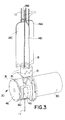
- a fluid-jet false-twisting apparatus is shown schematically in Figure 1 and generally indicated at broad reference numeral 10.
- multi-filament yarns 11 are taken from respective supply packages 12 and passed through a yarn separator 14, four twist-inserting air-jets, referred to as "twister blocks 15" (one for each yarn 11) and a rotary air jet assembly 20, where the yarn 11 is plied by the combined action of the twister blocks 15 and the rotary air jet assembly 20 in the manner according to the invention as described in this application.
- Air is supplied to the twister blocks 15 from a source of pressurized air by means of solenoid valves controlled by mechanical, electromechanical or, preferably, electronic means (not shown).
- the length of the yarn upstream of the twister blocks 15 can be less than twice the distance between each twist reversal, and in some applications as low as one-to-one, a substantial advantage over prior art processes.
- the yarns 11, now in plied form, are guided around overfeed drive rolls 22, 23 where the tension on the plied yarns 11 is reduced to a predetermined extent before delivery to a take-up package 25.
- Figure 2 shows the same fluid-jet false-twist apparatus 10 schematically in side elevation.
- a predetermined number of the fluid-jet false-twist apparatuses 10 will be positioned on a single frame for simultaneous operation.
- the number of units 10 on a single frame may be similar to the number of units on, for example, a winder.
- the yarn separator 14 has four elongate, vertically-oriented wings 14A-14D.
- the wings 14A-14D separate the yarn path into four physically-separate zones and thereby keep the individual yarns 11 from touching and twisting together prior to passage into the twister blocks 15.
- the yarns 11 above the twister blocks 15 are twisted in a Z-direction; the yarns 11 between the twister blocks 15 and the rotary air-jet assembly 20 are twisted in S-direction; and the plied yarn 11 below the rotary air-jet assembly 20 are twisted in Z-direction.
- Sufficient yarn length is needed upstream of the twister blocks 15 for the backed-up twist to accumulate.
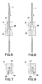
- each of the twister blocks 15 has a vertically-oriented bore 27 through which a respective yarn 11 passes.
- Each of the twister blocks 15 also has two air ducts 28, 29 which communicate with the bore 27 for communicating air flow. As is shown, the axes of respective ducts 28, 29 are laterally offset with respect to the axis of the bore 27. Therefore, one of the ducts 28, 29 supplies pressurized air which is laterally offset with respect to the axis of the yarn 11 passing through the bore 27 and impinges on the moving yarn 11 in such manner that the air in one of the ducts 28, 29 creates clockwise twist in the yarn 11 and the air in the other of the ducts 28, 29 creates counterclockwise twist.
- twister block 15 is shown with pressurized air being injected into duct 29 to insert twist in a clockwise manner, with the result that the yarn 11 above the twister block 15 has Z-twist and the yarn 11 below the twister block 15 has S-twist.
- Figure 6 shows twister block 15 in vertical cross-section
- Figure 7 shows a cross-section of the twister block 15 viewed from the bottom, again showing a clockwise twisting action by the air-jet generating S-twist in yarn 11 above the twister block 15 and Z-twist in the yarn 11 below the twister block 15.
- Figure 8 shows a twister block 15 in vertical cross-section
- Figure 9 shows a cross-section of the same twister block 15 viewed from the bottom.
- counterclockwise twist generates Z-twist in yarn 11 above the twister block 15 and S-twist in the yarn 15 below the twister block 15.
- four of these twister blocks 15 are grouped to receive respective yarns 11 as delivered from the upstream supply packages 12. See Figures 1 and 2.
- the plied yarn 11 is comprised of a "S"-twisted portion 11A, and an "Z"-twisted portion 11B separated by a twist reversal segment 11C constructed of entangled fibers in the manner described below.
- the spacing of these twist reversal segments 11C is a significant factor in the ultimate characteristics of the yarn.
- the twist in the yarns 11 is locked into the yarn in the alternate directions by the twist reversal segments 11C.
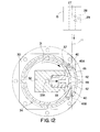
- a drive motor 30 is mounted on the machine frame (not shown).
- a protective shroud 31 is positioned on one side of the motor 30 and encloses several components of the rotary air-jet assembly 20.
- a manifold housing 32 is mounted in shroud 31 and carries an air manifold 33 which supplies pressurized air to the rotary air-jet assembly 20. Air is supplied to the manifold by an air inlet port 33A.
- a rotating, cylindrical air-jet carried for rotation on the motor shaft 35 of the drive motor 30.
- the air-jet nozzle 34 may be driven by a belt, gear transmission or other suitable power transmission device. Rotating nozzle 34 is provided with an air-jet orifice 37 through which air may pass at predetermined intervals.
- Shroud 31 is provided with a cut-away section 39 defined by the walls of shroud 31, into which is placed a yarn twister plate 40.
- Yarn guide plate 40 is provided with a vertically-oriented yarn slot 41 through which the plied yarns 11 pass after leaving the twister blocks 15.
- a yarn slot orifice 42 in the yarn slot 41 communicates with the air-jet nozzle 34.
- the yarn guide plate 40 fits over the cut-away section 39 to guide the plied yarn 11 properly past the air jet nozzle 34.
- a cover 45 is positioned over the yarn slot 41 of the yarn guide plate 40 to prevent uncontrolled escape of air from the proximity of the yarn 11 and to produce in cooperation with the yarn guide plate 40 the air turbulence which entangles the yarn 11.
- the cover 45 has an upstream yarn entrance 45A and a downstream yarn exit 45B.
- An end cap 46 encloses the end of the shroud 31. Note that the air-jet nozzle 34 is the only moving part of the air-jet assembly 20 other than the shaft and associated elements of the motor 30.
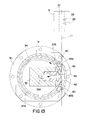
- Air inlet port 33A feeds pressurized air into the manifold 33. Air is ejected from the manifold through an air outlet port 48.
- the forward walls of the manifold 33 defining the air outlet port 48 are arcuately shaped to seal against the inside wall of rotating air-jet nozzle 34 to prevent air from escaping into the interior of the air-jet nozzle 34.
- the air-jet orifice 37 moves past the air outlet port 48.
- Each complete rotation thus creates a pulse of pressurized air which passes though the air outlet port 48, the air-jet orifice 37, the yarn slot orifice 42 and into the yarn slot 41 in the yarn guide plate 40.
- the distance between the air-jet nozzle 34 and the yarn guide plate 40 should be as short as possible in order to achieve a short, dense twist reversal segment 11C.
- two air-jet orifices 37A and 37B can be formed in the air-jet nozzle 34, thus permitting the formation of two twist reversal segments 11C for each rotation of the air-jet nozzle 34.
- Other arrangements are possible, and need not be symmetrical.
- twist reversal points which are at varying distances from each other can be created by selective-placement of air-jet orifices 37 at different spacings around the circumference of the air-jet nozzle 34.
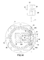
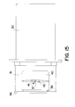
- Figures 14 and 15 illustrate the twist reversal formation position of the air-jet nozzle 34.
- the air-jet orifice 37 communicates for passage of pressurized air from the air-jet orifice 37 into the area of the yarn 11 by passing into the area of the yarn slot 41.
- the inside wall of the cover 45 acts as diffuser to create randomly swirling jets of high-pressure, high velocity blasts of air which pass in and through the yarn 11, tangling the yarn 11 at the point where the yarn 11 is exposed to the air blast and forming the twist reversal segments 11C.
- the air-jet nozzle 34 will entangle a given spot on the yarn 11 for each passage of the air-jet orifice 37 past the yarn slot 41.
- the length of the twist reversal segment 11C should be approximately no more than the length of the yarn slot orifice 42.
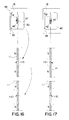
- the cover 45 is removed to show the position of the air-jet orifice 37. Note that in this view the air-jet orifice 37 is laterally centered with reference to the yarn slot orifice 42. In this position the air blast will create a generally symmetrical tangle of fibers in the yarn 11--neither favoring the Z-twist or S-twist direction.
- Figure 17 shows how the opposite occurs when the air-jet orifice 37 is moved laterally off center to the left.
- the proper arrangement for a short point of twist reversal is to use an air-jet nozzle 34 with two air-jet orifices 37A and 37B ( Figure 13) where one air-jet orifice 37A or 37B is laterally offset to the right of the yarn slot orifice 42 to entangle the plied yarn 11 when the twist changes from "Z" to "S”; and use the other of the air-jet orifices 37A or 37B, which is offset to the inside of the yarn slot orifice 42, to entangle the plied yarn 11 when the twist changes from "S" to "Z".
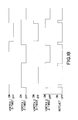
- the table illustrates that the active air-blast time of the rotary air-jet assembly 20 is used to time the "on” and “off” time of the twister blocks 15 for a air-jet nozzle 34 with a single air-jet orifice 37.
- the air to the "Vortex 2" (“Z-twist") twister block 15 is turned on before the air for the "Vortex 2" (“S-twist”) twister block 15 is turned off. This is accomplished through electronic timing. The same type of timing is also used for the "Vortex 1" (S-twist) and Vortex 2 (Z-twist) twister blocks 15.
- This overlapping timing can be used if desired to achieve a short as possible twist reversal segment 11C in the plied yarn 11 since there is some unavoidable delay in the time from when the solenoid is switched on until the air is fully active in the twister blocks 15.
- Figure 19 shows the timing for a rotary air-jet assembly 20 with an air-jet nozzle 34 having the two circumferentially-offset air-jet orifices 37A and 37B ( Figure 13) where the two air-jet orifices 37A and 37B are laterally offset to each other and are laterally displaced from the center of the yarn slot orifice 42 to accomplish a short twist reversal segment 11C.
- the timing diagram in Figure 20 shows how the rotational speed of the rotary air-jet assembly 20 is controlled.
- An electronic drive (not shown) for the rotary air-jet assembly 20 is programmed in such a manner that the air-jet orifice 37 reaches the velocity of the traveling plied yarn 11 during the time that entangling of the yarn 11 is taking place.
- the rotational speed of the air-jet nozzle 34 with its air-jet orifice 37 is slowed down between each splicing cycle in order to wait for the next twist-reversal, at which time it has been brought up speed to match the velocity of the plied yarn 11.
- the desired yarn-length between the twist reversal segments 11C and the processing speed of the yarn 11 dictates the velocity profile of the rotary air-jet assembly 20.
- the relationship of the rotary air-jet assembly 20 in relation to the plied yarn 11 is given in Figure 20.
- the rotational velocity of the air-jet nozzle 34 is timed in two basic ways:
- the air blast from the air-jet orifice 37 is timed to coincide with the passing of the point where the twist reversal segment 11C of the yarn 11 is to be formed.
- the rotational speed of the air jet nozzle 34 matches the velocity of the traveling yarn 11 in order that the air blast is, relatively speaking, stationary with the point of creation of the twist reversal segment 11C during the entangling process.
- the shaded area shown below the rotational velocity line in Figure 20 is the integral of the rotational velocity and the process time and is equal to the angular distance between two air-jet orifices 37A and 37B of the rotary air-jet assembly 20 shown in Figure 13.
- the electronic controller for the drive motor 30 of the rotary air-jet assembly 20 is not shown, but may be a known angular encoder on the drive motor 30. It is naturally understood that the distance between the twist reversal segments 11C can be changed through the electronic controller, which will automatically adjust the speed of the drive motor 30 and hence of the air-jet nozzle 34 to match the requirements of the system to cause tangling of the yarn 11 at the desired points of twist reversal, and matching of the velocity of the air-net nozzle 34 with the velocity of the traveling yarn 11.
- the electronic control of the rotary air-jet assembly 20 may be by an encoder on the drive of the take-up winder 25 ( Figure 1), which is then used as the master input for the electronic control, and from which the location of the point of twist reversal and the point where the yarn 11 is entangled is determined.
- a fluid-jet false-twisting apparatus according to another embodiment of the invention is shown and generally indicated at broad reference numeral 100.
- multi-filament yarns 101 are taken from respective supply packages 102 and passed through a yarn separator 104, four twist-inserting air-jets, referred to as "twister blocks 105" (one for each yarn 101) and a rotary air jet assembly 120, where the yarns 101 are plied by the combined action of the twister blocks 105 and the rotary air jet assembly 120 in the manner described above in relation to Figures 1-20.
- Air is supplied to the twister blocks 105 from a source of pressurized air by means of solenoid valves controlled by mechanical, electromechanical or, preferably, electronic means (not shown).
- the yarns 101 are guided around overfeed drive rolls 122, 123 where the tension on the plied yarns 101 is reduced to a predetermined extent before delivery to a yarn accumulator 130 and to a downstream take-up winder 140.
- the yarn accumulator may be a Belmont Model AC-50 accumulator, and the winder may be a Model AD-25 take-up winder.
- the yarn accumulator 130 helps buffer variations in yarn tension, and permits the system to continue operating during package changes. In addition, any lengths of defective yarn can easily be seen in the accumulator and removed during machine operation.
- the accumulator 130 may act as the "master encoder" for purposes of determining actuation of the various twist inserting and entangling functions described above.
- the overfeed drive rolls 122, 123 may be removed and replace with a nip roll (not shown), in which case the nip rolls may be used as the constant speed master off of which the other functions of the fluid-jet false-twisting apparatus 100 are timed.
Landscapes
- Engineering & Computer Science (AREA)
- Textile Engineering (AREA)
- Mechanical Engineering (AREA)
- Physics & Mathematics (AREA)
- Fluid Mechanics (AREA)
- Yarns And Mechanical Finishing Of Yarns Or Ropes (AREA)
Applications Claiming Priority (2)
| Application Number | Priority Date | Filing Date | Title |
|---|---|---|---|
| US5715297P | 1997-08-28 | 1997-08-28 | |
| US57152 | 2001-10-25 |
Publications (3)
| Publication Number | Publication Date |
|---|---|
| EP0899366A2 true EP0899366A2 (fr) | 1999-03-03 |
| EP0899366A3 EP0899366A3 (fr) | 2000-05-17 |
| EP0899366B1 EP0899366B1 (fr) | 2004-03-31 |
Family
ID=22008825
Family Applications (1)
| Application Number | Title | Priority Date | Filing Date |
|---|---|---|---|
| EP98306140A Expired - Lifetime EP0899366B1 (fr) | 1997-08-28 | 1998-07-31 | Appareil fausse torsion par jet de fluide, procédé et produit |
Country Status (4)
| Country | Link |
|---|---|
| US (2) | US6089009A (fr) |
| EP (1) | EP0899366B1 (fr) |
| CA (1) | CA2246801A1 (fr) |
| DE (1) | DE69822734T2 (fr) |
Cited By (3)
| Publication number | Priority date | Publication date | Assignee | Title |
|---|---|---|---|---|
| EP0979890A1 (fr) * | 1998-06-24 | 2000-02-16 | Belmont Textile Machinery Co., Inc. | Appareil à retordre par jet de fluide, et procédé |
| WO2010014411A3 (fr) * | 2008-07-30 | 2010-04-01 | Invista Technologies S.A R.L. | Systèmes et procédés de tordage et de thermofixage d'un fil, et appareil permettant le tordage d'un fil et le thermofixage d'un fil |
| WO2012156220A1 (fr) * | 2011-05-19 | 2012-11-22 | Oerlikon Textile Gmbh & Co. Kg | Procédé et dispositif pour produire des nœuds d'entrelacement dans un film multifilament |
Families Citing this family (9)
| Publication number | Priority date | Publication date | Assignee | Title |
|---|---|---|---|---|
| US7480969B2 (en) * | 2004-09-10 | 2009-01-27 | Rhyne Jeffrey T | Apparatus and method for conditioning air-entangled yarn |
| US7406818B2 (en) * | 2004-11-10 | 2008-08-05 | Columbia Insurance Company | Yarn manufacturing apparatus and method |
| DE102011015689A1 (de) * | 2011-03-31 | 2012-10-04 | Oerlikon Textile Gmbh & Co. Kg | Vorrichtung zum Erzeugen von Verwirbelungen an einem multifilen Faden |
| JP5877897B2 (ja) | 2011-06-16 | 2016-03-08 | エーリコン テクスティル ゲゼルシャフト ミット ベシュレンクテル ハフツング ウント コンパニー コマンディートゲゼルシャフトOerlikon Textile GmbH & Co. KG | 巻縮されたマルチフィラメント糸を製造する方法及び装置 |
| WO2013010688A1 (fr) * | 2011-07-15 | 2013-01-24 | Oerlikon Textile Gmbh & Co. Kg | Dispositif de production de nœuds d'entrelacement |
| JP6129175B2 (ja) * | 2011-08-30 | 2017-05-17 | エーリコン テクスティル ゲゼルシャフト ミット ベシュレンクテル ハフツング ウント コンパニー コマンディートゲゼルシャフトOerlikon Textile GmbH & Co. KG | 交絡結節点を形成する方法および装置 |
| WO2016164777A1 (fr) * | 2015-04-08 | 2016-10-13 | Shaw Industries Group, Inc. | Appareil et procédé de texturation de fil |
| US10570536B1 (en) | 2016-11-14 | 2020-02-25 | CFA Mills, Inc. | Filament count reduction for carbon fiber tow |
| WO2021226538A1 (fr) * | 2020-05-07 | 2021-11-11 | Universal Fibers, Inc. | Fils hélicoïdaux chiné |
Family Cites Families (96)
| Publication number | Priority date | Publication date | Assignee | Title |
|---|---|---|---|---|
| US2703316A (en) | 1951-06-05 | 1955-03-01 | Du Pont | Polymers of high melting lactide |
| CA646726A (en) * | 1958-08-01 | 1962-08-14 | E.I. Du Pont De Nemours And Company | Multifilament yarn and process for preparing |
| US3531561A (en) | 1965-04-20 | 1970-09-29 | Ethicon Inc | Suture preparation |
| US3744232A (en) * | 1971-04-05 | 1973-07-10 | Bigelow Sanford Inc | Composite false-twist yarn |
| US3775955A (en) * | 1971-07-30 | 1973-12-04 | Bigelow Sanford Inc | Composite false-twist yarns, methods and apparatus |
| BE790018A (fr) | 1971-10-14 | 1973-04-12 | Westinghouse Electric Corp | Ameliorations apportees ou se rapportant a des compositions resineuses |
| US3921333A (en) | 1972-07-28 | 1975-11-25 | Union Carbide Corp | Transplanter containers made from biodegradable-environmentally degradable blends |
| US3853820A (en) | 1973-07-23 | 1974-12-10 | Eastman Kodak Co | Blends of linear water-dissipatable polyesters and aliphatic or cycloaliphatic dicarboxylic acids |
| US4051660A (en) * | 1974-07-15 | 1977-10-04 | Akzona Incorported | Yarns and their method of manufacture |
| US3964486A (en) | 1974-08-19 | 1976-06-22 | The Procter & Gamble Company | Disposable diaper containing ammonia inhibitor |
| US4002012A (en) * | 1975-05-21 | 1977-01-11 | Champion International Corporation | Method and apparatus for splicing thermoplastic textile yarn |
| US4173115A (en) * | 1976-12-30 | 1979-11-06 | Wwg Industries, Inc. | Yarn forming apparatus with node welding |
| US4170868A (en) * | 1976-12-30 | 1979-10-16 | Wwg Industries, Inc. | Yarn forming apparatus with mechanical node locking |
| US4074511A (en) * | 1976-12-30 | 1978-02-21 | Champion International Corporation | Self twist yarn strand system |
| US4083172A (en) * | 1977-04-28 | 1978-04-11 | Champion International Corporation | Control system for pneumatically treated yarns |
| US4114549A (en) * | 1977-06-07 | 1978-09-19 | Champion International Corporation | Pile fabric |
| US4137921A (en) | 1977-06-24 | 1979-02-06 | Ethicon, Inc. | Addition copolymers of lactide and glycolide and method of preparation |
| US4215642A (en) * | 1977-10-25 | 1980-08-05 | Wwg Industries Inc. | Variable twist self-twist yarn |
| US4276740A (en) * | 1977-10-25 | 1981-07-07 | Wwg Industries, Inc. | Self-twisted yarn and method and apparatus for producing it |
| US4173861A (en) * | 1977-11-11 | 1979-11-13 | Wwg Industries, Inc. | Method and apparatus for controlling twist in yarn |
| US4142355A (en) * | 1977-11-18 | 1979-03-06 | Wwg Industries, Inc. | Self-twist yarn node fixation apparatus and method |
| US4175177A (en) | 1978-02-24 | 1979-11-20 | Union Carbide Corporation | Crosslinkable copolymer of a lactone and a polyfunctional acrylate |
| US4170103A (en) * | 1978-03-29 | 1979-10-09 | Wwg Industries, Inc. | Node fixation in self-twist yarn |
| US4186549A (en) * | 1978-05-30 | 1980-02-05 | Wwg Industries, Inc. | Packaging of self-twist yarns |
| US4279120A (en) * | 1978-06-08 | 1981-07-21 | Wwg Industries, Inc. | Self twist yarn and method and apparatus for making such yarns |
| US4246750A (en) * | 1979-07-24 | 1981-01-27 | Wwg Industries, Inc. | Self-twist yarn and method of making same |
| JPS5953945B2 (ja) | 1980-02-21 | 1984-12-27 | 東レ株式会社 | 繊維構造物の処理方法 |
| US4489056A (en) | 1982-06-30 | 1984-12-18 | Merck & Co., Inc. | Acid anhydrides as rate controlling agent for the erosion of polymers which latter polymers have beneficial substances dispersed throughout their matrix or where the polymer matrix surrounds the beneficial substance |
| US5160472A (en) | 1984-10-24 | 1992-11-03 | Zachariades Anagnostis E | Method of producing composite structures of ultra-high-molecular-weight polymers, such as ultra-high-molecular-weight polyethylene products |
| PH26954A (en) | 1985-05-15 | 1992-12-03 | Procter & Gamble | Disposable absorbent articles |
| US4710187A (en) | 1985-09-06 | 1987-12-01 | Kimberly-Clark Corporation | Form-fitting self-adjusting disposable garment with a stretchable bodyside liner |
| JPS6269822A (ja) | 1985-09-19 | 1987-03-31 | Chisso Corp | 熱接着性複合繊維 |
| US4762521A (en) | 1986-04-11 | 1988-08-09 | Kimberly-Clark Corporation | Absorbent garment with quilted and conformable absorbent pad |
| US4800219A (en) | 1986-12-22 | 1989-01-24 | E. I. Du Pont De Nemours And Company | Polylactide compositions |
| US4770656A (en) | 1986-12-31 | 1988-09-13 | Kimberly-Clark Corporation | Routing of leg elastic to reduce stresses in a stretchable outer diaper cover |
| CH671961A5 (fr) | 1987-02-27 | 1989-10-13 | Amrotex Ag | |
| US4983689A (en) | 1987-05-07 | 1991-01-08 | Yu Simon H | Process for making macromolecular monomers of polylactones with terminal acryloyl unsaturation and block copolymers thereof |
| US4798603A (en) | 1987-10-16 | 1989-01-17 | Kimberly-Clark Corporation | Absorbent article having a hydrophobic transport layer |
| DE3808843A1 (de) | 1988-03-17 | 1989-09-28 | Bayer Ag | Polymermischungen mit hoher zugfestigkeit und guter weiterreissfestigkeit |
| US4873821A (en) * | 1988-04-15 | 1989-10-17 | E. I. Du Pont De Nemours And Company | Apparatus and process for forming alternate twist plied yarn |
| US5228282A (en) * | 1988-04-15 | 1993-07-20 | E. I. Du Pont De Nemours And Company | Apparatus for forming alternate twist plied yarn |
| US5179827A (en) * | 1988-04-15 | 1993-01-19 | E. I. Du Pont De Nemours And Company | Alternate twist plied yarn |
| US5003763A (en) * | 1988-04-15 | 1991-04-02 | E. I. Du Pont De Nemours And Company | Apparatus and process for forming alternate twist plied yarn and product therefrom |
| US5012636A (en) * | 1988-04-15 | 1991-05-07 | E. I. Du Pont De Nemours And Company | Apparatus and process for forming alternate twist plied yarn and product therefrom |
| US5134840A (en) * | 1988-07-29 | 1992-08-04 | Niederer Kurt W | Twisted yarn product |
| US4934134A (en) * | 1988-07-29 | 1990-06-19 | Belmont Textile Machine Co. | Apparatus for randomizing multiple yarn strands |
| US5216050A (en) | 1988-08-08 | 1993-06-01 | Biopak Technology, Ltd. | Blends of polyactic acid |
| US5424346A (en) | 1988-08-08 | 1995-06-13 | Ecopol, Llc | Biodegradable replacement of crystal polystyrene |
| US5252642A (en) | 1989-03-01 | 1993-10-12 | Biopak Technology, Ltd. | Degradable impact modified polyactic acid |
| US5502158A (en) | 1988-08-08 | 1996-03-26 | Ecopol, Llc | Degradable polymer composition |
| US5444113A (en) | 1988-08-08 | 1995-08-22 | Ecopol, Llc | End use applications of biodegradable polymers |
| US5180765A (en) | 1988-08-08 | 1993-01-19 | Biopak Technology, Ltd. | Biodegradable packaging thermoplastics from lactides |
| US5069970A (en) | 1989-01-23 | 1991-12-03 | Allied-Signal Inc. | Fibers and filters containing said fibers |
| JP2682130B2 (ja) | 1989-04-25 | 1997-11-26 | 三井石油化学工業株式会社 | 柔軟な長繊維不織布 |
| US5057368A (en) | 1989-12-21 | 1991-10-15 | Allied-Signal | Filaments having trilobal or quadrilobal cross-sections |
| US5056200A (en) * | 1990-01-09 | 1991-10-15 | Textured Yarn Company, Inc. | Apparatus for making novel textured yarn |
| US5273596A (en) | 1990-03-21 | 1993-12-28 | Fiberweb North America, Inc. | Nonwoven fabric for diaper top sheet and method of making the same |
| JPH0457948A (ja) | 1990-06-26 | 1992-02-25 | Unitika Ltd | 自己分解性三次元網目構造不織布 |
| US5076983A (en) | 1990-07-16 | 1991-12-31 | E. I. Du Pont De Nemours And Company | Polyhydroxy acid films |
| JP3311371B2 (ja) | 1991-11-15 | 2002-08-05 | 三井化学株式会社 | 緩衝材 |
| US5223546A (en) | 1991-04-24 | 1993-06-29 | Mitsui Toatsu Chemicals, Inc. | High polymer network |
| US5238968A (en) | 1991-04-24 | 1993-08-24 | Mitsui Toatsu Chemicals, Inc. | Process for preparing a degradable high polymer network |
| US5340646A (en) | 1991-04-26 | 1994-08-23 | Mitsui Toatsu Chemicals, Inc. | Breathable, hydrolyzable porous film |
| US5405887A (en) | 1991-04-26 | 1995-04-11 | Mitsui Toatsu Chemicals, Inc. | Porous film |
| EP0525245A1 (fr) | 1991-08-01 | 1993-02-03 | NOVAMONT S.p.A. | Articles absorbants jetables |
| US5412005A (en) | 1991-05-03 | 1995-05-02 | Novamont S.P.A. | Biodegradable polymeric compositions based on starch and thermoplastic polymers |
| CA2068368A1 (fr) | 1991-05-13 | 1992-11-14 | Masanobu Ajioka | Composition de lamelles degradables |
| CA2067451A1 (fr) | 1991-05-24 | 1993-10-29 | Gregory B. Kharas | Melanges de polylactide |
| US5277976A (en) | 1991-10-07 | 1994-01-11 | Minnesota Mining And Manufacturing Company | Oriented profile fibers |
| US5162153A (en) | 1991-12-23 | 1992-11-10 | Hoechst Celanese Corporation | Poly(butylene terephthalate) copolyester and a process for preparing it |
| US5202178A (en) | 1992-02-28 | 1993-04-13 | International Paper Company | High-strength nylon battery separator material and related method of manufacture |
| US5258422A (en) | 1992-05-05 | 1993-11-02 | Tredegar Industries, Inc. | Compostable thermoplastic compositions |
| EP0569146B1 (fr) | 1992-05-08 | 2000-02-09 | Showa Highpolymer Co., Ltd. | Film de polyester |
| US5294469A (en) | 1992-06-17 | 1994-03-15 | Mitsui Toatsu Chemicals, Incorporated | Industrial woven fabric and composite sheet comprising same |
| US5241066A (en) | 1992-06-25 | 1993-08-31 | Basf Corporation | Method of recovering caprolactam from mixed waste |
| US5382400A (en) | 1992-08-21 | 1995-01-17 | Kimberly-Clark Corporation | Nonwoven multicomponent polymeric fabric and method for making same |
| US5336552A (en) | 1992-08-26 | 1994-08-09 | Kimberly-Clark Corporation | Nonwoven fabric made with multicomponent polymeric strands including a blend of polyolefin and ethylene alkyl acrylate copolymer |
| KR100209818B1 (ko) | 1992-09-04 | 1999-07-15 | 사또 아끼오 | 분해성점착필름 및 분해성수지조성물 |
| US5338822A (en) | 1992-10-02 | 1994-08-16 | Cargill, Incorporated | Melt-stable lactide polymer composition and process for manufacture thereof |
| BR9305661A (pt) | 1992-10-02 | 1996-11-26 | Cargill Inc | Pano de polímero de lactideo estável em fusao e processo para a sua fabricaçao |
| US5321068A (en) | 1992-11-24 | 1994-06-14 | E. I. Du Pont De Nemours And Company | Fiber of polyadipamide polymer containing added succinic acid |
| JP3264720B2 (ja) | 1993-01-12 | 2002-03-11 | ユニチカ株式会社 | 生分解性複合短繊維不織布 |
| US5465566A (en) * | 1993-06-08 | 1995-11-14 | E. I. Du Pont De Nemours And Company | Alternate twist-plied yarn |
| US5462983A (en) | 1993-07-27 | 1995-10-31 | Evercorn, Inc. | Biodegradable moldable products and films comprising blends of starch esters and polyesters |
| US5618911A (en) | 1993-08-19 | 1997-04-08 | Toyo Boseki Kabushiki Kaisha | Polymer containing lactic acid as its constituting unit and method for producing the same |
| US5593778A (en) | 1993-09-09 | 1997-01-14 | Kanebo, Ltd. | Biodegradable copolyester, molded article produced therefrom and process for producing the molded article |
| WO1995017216A1 (fr) | 1993-12-20 | 1995-06-29 | The Procter & Gamble Company | COMPOSITIONS POLYMERES A pH MODIFIE PRESENTANT UNE BIODEGRADABILITE AMELIOREE |
| DE69509927T2 (de) | 1994-01-21 | 2000-01-27 | Shimadzu Corp., Kyoto | Methode zur Herstellung von Polymilchsäure |
| US5500465A (en) | 1994-03-10 | 1996-03-19 | Board Of Trustees Operating Michigan State University | Biodegradable multi-component polymeric materials based on unmodified starch-like polysaccharides |
| WO1995025190A1 (fr) * | 1994-03-16 | 1995-09-21 | E.I. Du Pont De Nemours And Company | Procede et dispositif de fabrication de fil retors simple en alternance reguliere de torsadage et produit resultant |
| JP2917094B2 (ja) * | 1994-05-24 | 1999-07-12 | 日清紡績株式会社 | エア交絡方法及びエア交絡機 |
| US5619849A (en) * | 1994-08-26 | 1997-04-15 | Caress Yarns, Inc. | Method and apparatus for producing randomly variegated multiple strand yarn in twisting together at least two yarns and yarn and fabric made by said method |
| US5557915A (en) * | 1994-11-14 | 1996-09-24 | E. I. Du Pont De Nemours And Company | Method and apparatus for making alternate twist plied yarn and product |
| US5637631A (en) | 1994-11-17 | 1997-06-10 | Mitsui Toatsu Chemicals, Inc. | Preparation process of degradable polymer |
| FR2733520B1 (fr) | 1995-04-26 | 1997-06-06 | Fiberweb Sodoca | Structure composite biodegradable non tisse/film |
| US5691424A (en) | 1995-05-25 | 1997-11-25 | Mitsui Toatsu Chemicals, Inc. | Heat-resistant molded article of lactic acid-base polymer |
-
1998
- 1998-04-09 US US09/058,010 patent/US6089009A/en not_active Expired - Lifetime
- 1998-07-31 DE DE69822734T patent/DE69822734T2/de not_active Expired - Fee Related
- 1998-07-31 EP EP98306140A patent/EP0899366B1/fr not_active Expired - Lifetime
- 1998-08-27 CA CA002246801A patent/CA2246801A1/fr not_active Abandoned
-
1999
- 1999-06-08 US US09/327,846 patent/US6195975B1/en not_active Expired - Fee Related
Cited By (5)
| Publication number | Priority date | Publication date | Assignee | Title |
|---|---|---|---|---|
| EP0979890A1 (fr) * | 1998-06-24 | 2000-02-16 | Belmont Textile Machinery Co., Inc. | Appareil à retordre par jet de fluide, et procédé |
| WO2010014411A3 (fr) * | 2008-07-30 | 2010-04-01 | Invista Technologies S.A R.L. | Systèmes et procédés de tordage et de thermofixage d'un fil, et appareil permettant le tordage d'un fil et le thermofixage d'un fil |
| US8528310B2 (en) | 2008-07-30 | 2013-09-10 | Invista North America S.ár.l. | Systems and methods of twisting and heat-setting yarn, and apparatus for twisting yarn and heat-setting yarn |
| WO2012156220A1 (fr) * | 2011-05-19 | 2012-11-22 | Oerlikon Textile Gmbh & Co. Kg | Procédé et dispositif pour produire des nœuds d'entrelacement dans un film multifilament |
| US9422647B2 (en) | 2011-05-19 | 2016-08-23 | Oerlikon Textile Gmbh & Co. Kg | Method and apparatus for producing intertwined knots in a multifilament thread |
Also Published As
| Publication number | Publication date |
|---|---|
| DE69822734T2 (de) | 2005-03-17 |
| DE69822734D1 (de) | 2004-05-06 |
| CA2246801A1 (fr) | 1999-02-28 |
| US6195975B1 (en) | 2001-03-06 |
| EP0899366A3 (fr) | 2000-05-17 |
| EP0899366B1 (fr) | 2004-03-31 |
| US6089009A (en) | 2000-07-18 |
Similar Documents
| Publication | Publication Date | Title |
|---|---|---|
| US6089009A (en) | Fluid-jet false-twisting method and product | |
| EP0979890B1 (fr) | Appareil à retordre par jet de fluide, et procédé | |
| US6085395A (en) | Method and apparatus for producing a multicolored yarn from differently colored part-threads of endless filament | |
| US5640745A (en) | Method and apparatus for the manufacture of a mixed yarn using multifilament yarn and fibers | |
| US4159619A (en) | Method for producing novelty yarns | |
| US5008992A (en) | Method of producing a bulked composite yarn | |
| US4736578A (en) | Method for forming a slub yarn | |
| US4058968A (en) | Bulked yarn and method of forming a bulked yarn | |
| JP3439771B2 (ja) | フィラメントヤーンをエアー・トリートメントするための方法並びに装置 | |
| CN103620098A (zh) | 用于生产卷曲变形的多纤维长丝的方法和设备 | |
| RU2091518C1 (ru) | Устройство для обработки по меньшей мере одной движущейся комплексной нити обдувочной средой | |
| US5054173A (en) | Method and apparatus for the enhanced crimping of multifilament yarn | |
| US5134840A (en) | Twisted yarn product | |
| US4934134A (en) | Apparatus for randomizing multiple yarn strands | |
| US6820405B2 (en) | Device for producing effect yarns and use of the device | |
| US3742692A (en) | Apparatus and method for false twisting yarn | |
| US3678549A (en) | Process for the manufacture of high-bulk yarn | |
| GB2321651A (en) | Producing interlaced yarns | |
| US5901544A (en) | Method and apparatus for producing randomly variegated multiple strand twisted yarn and yarn and fabric made by said method | |
| US4949440A (en) | Method and apparatus for twisting yarn, and product | |
| US7299615B2 (en) | Variable twist level yarn using fluid twisting | |
| JPH09111562A (ja) | 合成フィラメント糸のスタッファボックス捲縮方法及び装置 | |
| US5619849A (en) | Method and apparatus for producing randomly variegated multiple strand yarn in twisting together at least two yarns and yarn and fabric made by said method | |
| US4162607A (en) | Entangled yarns | |
| US3710461A (en) | Method and apparatus for intermittently texturing yarn |
Legal Events
| Date | Code | Title | Description |
|---|---|---|---|
| PUAI | Public reference made under article 153(3) epc to a published international application that has entered the european phase |
Free format text: ORIGINAL CODE: 0009012 |
|
| AK | Designated contracting states |
Kind code of ref document: A2 Designated state(s): DE FR GB IT |
|
| AX | Request for extension of the european patent |
Free format text: AL;LT;LV;MK;RO;SI |
|
| PUAL | Search report despatched |
Free format text: ORIGINAL CODE: 0009013 |
|
| AK | Designated contracting states |
Kind code of ref document: A3 Designated state(s): AT BE CH CY DE DK ES FI FR GB GR IE IT LI LU MC NL PT SE |
|
| AX | Request for extension of the european patent |
Free format text: AL;LT;LV;MK;RO;SI |
|
| 17P | Request for examination filed |
Effective date: 20000925 |
|
| AKX | Designation fees paid |
Free format text: DE FR GB IT |
|
| 17Q | First examination report despatched |
Effective date: 20020830 |
|
| GRAH | Despatch of communication of intention to grant a patent |
Free format text: ORIGINAL CODE: EPIDOS IGRA |
|
| GRAH | Despatch of communication of intention to grant a patent |
Free format text: ORIGINAL CODE: EPIDOS IGRA |
|
| GRAA | (expected) grant |
Free format text: ORIGINAL CODE: 0009210 |
|
| AK | Designated contracting states |
Kind code of ref document: B1 Designated state(s): DE FR GB IT |
|
| REG | Reference to a national code |
Ref country code: GB Ref legal event code: FG4D |
|
| REF | Corresponds to: |
Ref document number: 69822734 Country of ref document: DE Date of ref document: 20040506 Kind code of ref document: P |
|
| PGFP | Annual fee paid to national office [announced via postgrant information from national office to epo] |
Ref country code: GB Payment date: 20040726 Year of fee payment: 7 |
|
| PGFP | Annual fee paid to national office [announced via postgrant information from national office to epo] |
Ref country code: FR Payment date: 20040727 Year of fee payment: 7 |
|
| PGFP | Annual fee paid to national office [announced via postgrant information from national office to epo] |
Ref country code: DE Payment date: 20040915 Year of fee payment: 7 |
|
| ET | Fr: translation filed | ||
| PLBE | No opposition filed within time limit |
Free format text: ORIGINAL CODE: 0009261 |
|
| STAA | Information on the status of an ep patent application or granted ep patent |
Free format text: STATUS: NO OPPOSITION FILED WITHIN TIME LIMIT |
|
| 26N | No opposition filed |
Effective date: 20050104 |
|
| PG25 | Lapsed in a contracting state [announced via postgrant information from national office to epo] |
Ref country code: IT Free format text: LAPSE BECAUSE OF NON-PAYMENT OF DUE FEES Effective date: 20050731 Ref country code: GB Free format text: LAPSE BECAUSE OF NON-PAYMENT OF DUE FEES Effective date: 20050731 |
|
| PG25 | Lapsed in a contracting state [announced via postgrant information from national office to epo] |
Ref country code: DE Free format text: LAPSE BECAUSE OF NON-PAYMENT OF DUE FEES Effective date: 20060201 |
|
| PG25 | Lapsed in a contracting state [announced via postgrant information from national office to epo] |
Ref country code: FR Free format text: LAPSE BECAUSE OF NON-PAYMENT OF DUE FEES Effective date: 20060228 |
|
| GBPC | Gb: european patent ceased through non-payment of renewal fee |
Effective date: 20050731 |
|
| REG | Reference to a national code |
Ref country code: FR Ref legal event code: ST Effective date: 20060228 |