EP0899088B1 - Waste compactor with a bale ejecting apparatus - Google Patents
Waste compactor with a bale ejecting apparatus Download PDFInfo
- Publication number
- EP0899088B1 EP0899088B1 EP98116417A EP98116417A EP0899088B1 EP 0899088 B1 EP0899088 B1 EP 0899088B1 EP 98116417 A EP98116417 A EP 98116417A EP 98116417 A EP98116417 A EP 98116417A EP 0899088 B1 EP0899088 B1 EP 0899088B1
- Authority
- EP
- European Patent Office
- Prior art keywords
- press
- rear wall
- shaft
- waste material
- guide
- Prior art date
- Legal status (The legal status is an assumption and is not a legal conclusion. Google has not performed a legal analysis and makes no representation as to the accuracy of the status listed.)
- Expired - Lifetime
Links
Images


Classifications
-
- B—PERFORMING OPERATIONS; TRANSPORTING
- B30—PRESSES
- B30B—PRESSES IN GENERAL
- B30B9/00—Presses specially adapted for particular purposes
- B30B9/30—Presses specially adapted for particular purposes for baling; Compression boxes therefor
- B30B9/3003—Details
- B30B9/3014—Ejection means
Abstract
Description
Die Erfindung betrifft eine Abfallpresse mit Auswurfeinrichtung
nach dem Oberbegiff des Patentanspruches 1,
in der Kartonagen, Folien und ähnliche verbrauchte
Verpackungsmaterialien zu Ballen gepreßt werden.The invention relates to a waste press with ejection device
according to the preamble of
Bekannt sind bereits Abfallpressen mit einer Auswurfeinrichtung, die im Bodenbereich des Schachtes der Presse eine zur Türöffnung hin schwenkbare Hubplatte aufweisen. Die Antriebseinrichtung für die Hubbewegung zum Schwenken der besagten Hubplatte ist bei diesen Abfallpressen außen an der Rückwand des Pressengehäuses angeordnet. Die Bauelemente zur Verbindung der Hubplatte mit der Antriebseinheit sind dort durch einen in der Rückwand des Pressengehäuses vorgesehenen, bis in den Preßbereich hinunter reichenden Schlitz bzw. Schlitze hindurch nach außen geführt, siehe hierzu die US-A-4,311,092. Diese Art von Auswurfeinrichtungen sind wegen der Hydraulik und den zusätzlich vorzusehenden Sicherheitsschaltungen im Steuerungsprogramm kosten- und wartungsintensiv, zudem können durch den bis in den Preßbereich hinunter reichenden Schlitz zu pressende Materialien nach außen gelangen bzw. treten durch Verstopfungen des Schlitzes häufig Havariefälle ein, die die effektive Auslastung der Presse mindern.Waste presses are already known with an ejection device, in the bottom area of the shaft of the press have a pivotable to the door opening lifting plate. The drive device for the lifting movement for pivoting said lifting plate is outside in these waste presses arranged on the rear wall of the press housing. The components for connecting the lifting plate to the drive unit are there by one in the back wall of the press housing provided, down to the pressing area reaching slot or slots through to the outside see US-A-4,311,092. This kind of Ejectors are due to the hydraulic and the additionally to be provided safety circuits in the control program cost and maintenance intensive, besides, can through the reaching down into the pressing area Slot to be pressed materials to the outside or Clogging cases often occur through blockages of the slot which reduce the effective utilization of the press.
Bei anderen Auswurfeinrichtungen, wie z. B. nach der US-A-4,182,236, werden an der Fronttüranschlagkante im Bodenbereich des Schachtes der Presse verankerte Seile durch besagte Schlitze in der Rückwand hindurch geführt und zwecks Ruheposition an letzterer durch Handbetätigung einzeln eingehangen. In Vorbereitung des Arbeitsschrittes 'Ballen auswerfen' werden an den Seilenden angebrachte Haken durch die besagten Schlitze in der Rückwand hindurch in Löcher der Preßplatte eingehangen. Beim Hochfahren der bis dahin auf den Ballen einwirkenden Preßplatte werden die Seile in Richtung Türöffnung gespannt und werfen den fertigen Ballen aus. Bei dieser Bauart erschwert das auf die Preßplattenunterseite wirkende gepreßte Material das Einführen der Haken der Seile in die Löcher der Preßplatte. Darüber hinaus sind bei den Vorbereitungen für den nächsten Preßvorgang zusätzliche Handgriffe für das Legen der Seile in die vorgeschriebene Position notwendig. Weiterhin sind auch bei dieser Lösung Sicherheitsshaltungen im Steuerungsprogramm notwendig, damit die Auswurfeinrichtung nicht bei geschlossener Fronttür betätigbar ist, um erhebliche Schäden an der Presse zu vermeiden.For other ejectors, such. B. after US-A-4,182,236, are at the front door stop edge in Ground area of the shaft of the press anchored ropes passed through said slots in the rear wall and for rest position on the latter by manual operation individually hung. In preparation for the work step 'Eject Bales' are attached to the rope ends Hook through said slots in the back wall hung in holes of the press plate. When booting the until then acting on the bale press plate are the Ropes stretched towards the door opening and throw the finished bales. This makes it difficult the press plate bottom acting pressed material Insert the hooks of the ropes into the holes of the press plate. In addition, are in the preparations for the next Pressing additional handles for laying the ropes necessary in the prescribed position. Furthermore are also with this solution safety postures in the control program necessary, so that the ejector is not included closed front door is operable to considerable To avoid damage to the press.
US-A-3 916 781 und DE-A-2 630 906 zeigen auch Auswurfeinrichtungen ähnlicher konstruktion.US-A-3,916,781 and DE-A-2 630 906 also show ejectors similar construction.
Daher hat die Anmelderin in der Vergangenheit unter anderem Auswurfeinrichtungen an Ballenpressen vorgesehen, die eine bodenseitige Hubplatte, ein im Schacht der Presse in bzw. an der Rückwand im wesentlichen vertikal bewegbares, mit der Hubplatte gelenkig verbundenes Zugmittel, vorzugsweise eine Zugstange, aufweisen, wobei erst nach geöffneter Fronttür ein im Bereich der Rückwand auf der Oberseite der Preßplatte angeordnetes, schwenkbares bzw. verschiebbares Mitnahmeteil am oberen Ende des besagten Zugmittels handbetätigt in eine Öse eingehakt werden kann. Zwischen Preßplatte und Rückwand befindliches, gepreßtes Verpakkungsmaterial erschwert dort das Einhaken des Mitnahmeteiles. Zudem muß der Bediener der Presse zum Betätigen des besagten Mitnahmeteiles bei auf dem Ballen aufgesetzter Position der Preßplatte über selbige hinüber und an den mit der Preßplatte verbundenen Preßstempel seitlich vorbei greifen, wobei der Bediener in der Regel mit seinem Oberkörper in den Schacht der Presse hinein gerät; während des Arbeitsschrittes müssen Sicherheitsschaltungen im Steuerungsprogramm ein unbeabsichtigtes Betätigen der Preßplatte absolut verhindern. Danach nimmt das Mitnahmeteil während der anschließenden Aufwärtsbewegung der Preßplatte das Zugmittel, vorzugsweise die Zustange, mit und die bodenseitige Hubplatte wird zum Auswerfen des fertigen, verschnürten Ballen in Richtung der freigegebenen Türöffnung angekippt; in Vorbereitung des nächsten Preßvorganges muß die Preßplatte zum Ausschalten der Auswurfeinrichtung vorerst wieder in die untere Position und anschließend nochmals nach oben gefahren werden.Therefore, the Applicant has in the past, among others Ejection devices provided on balers, the one bottom-side lifting plate, one in the shaft of the press in or on the rear wall substantially vertically movable, with the lifting plate articulated connected traction means, preferably a pull rod, having, after open Front door in the area of the rear wall on the top of the Preßplatte arranged, pivotable or movable Driving part at the upper end of said traction means can be manually hooked into an eye. Between Press plate and rear wall located, compressed packaging material there makes it difficult to hook the entrainment part. In addition, the operator must press the press to operate the said entrainment part attached to the bale Position of the press plate over selbige over and to the with the press plate connected punch laterally over grab, with the operator usually with his upper body gets into the shaft of the press; while of the work step must safety circuits in the Control program unintentional operation of the Absolutely prevent pressure plate. After that takes the driving part during the subsequent upward movement of the Press plate the traction means, preferably the Zustange, with and the bottom-side lifting plate is for ejecting the finished, tied bales in the direction of the released Door opening tilted; in preparation for the next Pressing must the pressing plate to turn off the Ejector for the time being again in the lower position and then be driven up again.
Die Erfindung hat daher die Aufgabe, eine Abfallpresse mit Auswurfeinrichtung für Ballen zu schaffen, bei der die voranstehenden Nachteile im Wesentlichen nicht mehr vorhanden sind und die in ihrem konstruktiven Aufbau robust, störunanfällig und preiswert ist sowie weitere Verbesserungen der Arbeitsbedingungen des Bedieners gewährleistet.The invention therefore has the task of a waste press to provide with ejector for bales, in which the above disadvantages are essentially no longer are present and in their constructive structure robust, prone to interference and inexpensive and more Improvements in the working conditions of the operator guaranteed.
Erfindungsgemäß löst diese Aufgabe eine Abfallpresse mit
Auswurfeinrichtung für Ballen nach dem Patentanspruch 1
oder nach dem Patentanspruch 2;
die nachgeordneten Patentansprüche 3 bis 12 offenbaren
vorteilhafte Weiterbildungen bzw. Ausführungsvarianten
dieser beiden erfinderischen Basislösungen. According to the invention this object solves a waste press with ejection device for bales according to
the subordinate claims 3 to 12 disclose advantageous developments or variants of these two inventive basic solutions.
Diese beiden Basislösungen einer Abfallpresse mit
Auswurfeinrichtung für Ballen zeichnen sich dabei durch
die vorgesehene mechanische Zwangskopplung der Antriebselemente
der Auswurfeinrichtung mit der Position der den
Schacht der Presse verschließenden Fronttür F sowie durch
das automatische Einschalten der Auswurfeinrichtung beim
Hochfahren der Preßplatte nach Erreichen der Arbeitsposition
'Ballen fertig' aus, wobei zudem nach Auswurf
des fertigen Ballen die Auswurfeinrichtung in die Ausgangsposition
zurück fällt.
Die Basislösung nach dem Patentanspruch 2 unterscheidet
sich zur Basislösung nach dem Patentanspruch 1 durch die
Verwendung anderer Konstruktionselemente, dabei vor allem
darin, daß anstelle einer mehrteiligen Gestängeführung
hier das mechanisch wirkende Führungsmittel der Verbindungseinheit
als zweiarmiger Schwenkhebel ausgebildet ist.These two basic solutions of a waste press with ejector for bales are characterized by the proposed mechanical forced coupling of the drive elements of the ejector with the position of the shaft of the press closing front door F and by automatically switching on the ejector when starting the press plate after reaching the working position 'bales finished ', wherein also after ejection of the finished bale, the ejector falls back into the starting position.
The basic solution according to
Weiterbildungen der Erfindung bestehen noch darin, daß bei vollständig geschlossener Fronttür F oder bereits bei sich schließender Fronttür F, jedoch mindestens vor jeder dem Arbeitsschritt 'Ballenauswurf' folgenden, abwärts gerichteten Bewegung der Preßplatte C die Auswurfeinrichtung in ihre Ausgangsposition zurückgesetzt ist bzw. wird. Diese vorgesehene Zwangssteuerung verhindert, daß Teile der Verbindungseinheit, insbesondere der Mitnahmebolzen 6, der Auswurfeinrichtung mit dem an der Preßplatte C angeordneten Mitnehmer M, M' kollidieren.Further developments of the invention are that with completely closed front door F or already with closing front door F, but at least before each following the step 'bale ejection', downward movement of the pressing plate C the ejector reset to its original position is or will be. This intended positive control prevents that parts of the connection unit, in particular the Mitnahmebolzen 6, the ejector with the at the Press plate C arranged driver M, M 'collide.
Die Erfindung wird anhand von schematisiert in Zeichnungen
dargestellten Ausführungsbeispielen im folgenden
noch näher erläutert.
Im einzelnen zeigen:
- Fig. 1
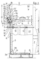
- eine Abfallpresse in teilweise geschnittener
Seitenansicht von links mit der neu gestalteten
Auswurfeinrichtung für Ballen nach der Basislösung
gem.
Patentanspruch 1, mit geschlossener Fronttür und ausgeschwenkter Verbindungseinheit (Position Ruhe); - Fig. 2
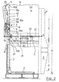
- die Abfallpresse nach Fig. 1 mit geöffneter Fronttür und eingeschwenkter Verbindungseinheit, Preßplatte in Position 'Ballen fertig';
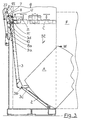
- Fig. 3
- die Abfallpresse nach Fig. 1 mit geöffneter Fronttür, eingeschwenkter Verbindungseinheit und Position 'Ballen-Auswurf';
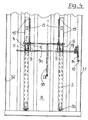
- Fig. 4
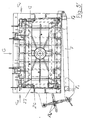
- eine Ansicht auf die Rückwand des Pressengehäuses nach Fig. 1 mit Anordnung einer weiteren Ausführungsvariante, einer mehrteiligen Auswurfeinrichtung;
- Fig. 5
- die Anordnung eines Sicherheitsschalters im Bewegungsbereich der Fronttür und
- Fig. 6
- eine Sicht in den Schacht der Presse bei einer Ausführung nach der Fig. 4.
- Fig. 1'
- eine Abfallpresse in teilweise geschnittener
Seitenansicht mit der neu gestalteten Auswurfeinrichtung
für Ballen nach der Basislösung
gem.
Patentanspruch 2, mit geschlossener Fronttür sowie in Ruheposition; - Fig. 2'
- die Abfallpresse nach Fig. 1' mit geöffneter Fronttür und eingeschwenkter Verbindungseinheit, mit einer Preßplatte in Position "Ballen fertig";
- Fig. 3'
- die Ahfallpresse nach Fig. 1' mit geöffneter Fronttür, eingeschwenkter Verbindungseinheit und Position "Ballen-Auswurf",
- Fig. 4'
- eine Ansicht auf die Rückwand des Pressengehäuses einer Abfallpresse gem. Fig. 1' und
- Fig. 5'
- eine Ansicht von oben in den Schacht einer Abfallpresse nach der vorliegenden Erfindung gem. der Fig. 1'.
In detail show:
- Fig. 1
- a waste press in a partially sectioned side view from the left with the newly designed ejection device for bales after the base solution acc.
Claim 1, with the front door closed and pivoted connection unit (position rest); - Fig. 2
- the waste press of Figure 1 with open front door and swiveled connection unit, press plate in position 'bale ready'.
- Fig. 3
- the waste press of Figure 1 with open front door, pivoted connection unit and position 'bale ejection'.
- Fig. 4
- a view of the rear wall of the press housing of Figure 1 with arrangement of another embodiment, a multi-part ejector.
- Fig. 5
- the arrangement of a safety switch in the range of movement of the front door and
- Fig. 6
- a view into the shaft of the press in an embodiment of FIG. 4th
- Fig. 1 '
- a waste press in a partially sectioned side view with the newly designed ejection device for bales after the base solution acc.
Claim 2, with the front door closed and in rest position; - Fig. 2 '
- the waste press of Figure 1 'with the front door open and swiveled connection unit, with a press plate in position "bale finished".
- Fig. 3 '
- the delivery press according to FIG. 1 'with the front door open, the connection unit pivoted in and the position "bale ejection",
- 4 '
- a view of the rear wall of the press housing of a waste press acc. Fig. 1 'and
- Fig. 5 '
- a view from above into the shaft of a waste press according to the present invention acc. of Fig. 1 '.
Bei der in den Figuren 1 bis 3 gezeigten Ausführungsvariante
einer Abfallpresse nach der ersten Basislösung,
die ein Pressengehäuse G, mit einer linken Seitenwand S1,
einer rechten Seitenwand S2, einer Rückwand R, einer
Fronttür F, mit integrierter Einfüllklappe, und einer
Bodenfläche B, und einen vom Pressengehäuse umgebenen
Schacht S, mit mindestens einem Preßbereich P und einem
darüber befindlichen Einfüllbereich E, aufweist, ist auf
der Bodenfläche B eine kippbare Hubplatte 2 und im Preßbereich
P des Schachtes S, in der bis zur Bodenfläche B
reichenden vertikalen Nut N der Rückwand R, eine mit der
Hubplatte 2 durch ein Scharnier 3b gelenkig verbundene
Zugstange 3 angeordnet, die nach der vorliegenden neuen
Bauart mit ihrem oberen Ende bis in den Einfüllbereich E
reicht und dort mit einem nach außen ragenden Schenkel 3d
ausgestattet und durch einen in letzterem 3d befestigten
Stab 16 gegen Hineinfallen in den Schacht gesichert ist.In the embodiment shown in Figures 1 to 3
a waste press after the first basic solution,
a press housing G, with a left side wall S1,
a right side wall S2, a rear wall R, a
Front door F, with integrated filler flap, and one
Bottom surface B, and one surrounded by the press housing
Shaft S, with at least one pressing area P and a
above filling area E, is on
the bottom surface B a
Das die Zugstange 3 der Auswurfeinrichtung 1 zeitweilig mit
der Preßplatte C verbindende, sonst in bekannter Art kippbar
auf der Oberseite der Preßplatte C angeordnete sogenannte
Koppelteil, ist in der vorliegenden Ausführungsvariante
durch die neuartige Verbindungseinheit der Auswurfeinrichtung
1 ersetzt. Diese neue Verbindungseinheit besteht
aus einem Schwenkstück 4, daß mit einer Welle 5 am oberen
Ende der Zugstange 3 gelenkig befestigt und mit einem
Mitnahmebolzen 6 sowie einem Druckbolzen 7 versehen ist,
aus einem oberen U-förmigen Führungsteil 8 mit vorzugsweise
langen Schenkeln 8a und 8b, die einen oberen
Abschnitt 10a bilden, und einem unteren ebenfalls U-förmigen
Führungsteil 9 mit vorzugsweise kurzen Schenkeln 9a
und 9b, die einen unteren Abschnitt 10b bilden, wobei die
Enden der Schenkel 8a, 8b und 9a,9b der beiden Führungsteile
8 und 9 einander zugewandt und etwas überlappend eine
gemeinsam geschlossene, ortsveränderliche Führung 10 für
den im Schwenkstück 4 befestigten Druckbolzen 7 bilden.
Die Führungsteile 8 und 9 sind jeweils mit einer Welle 8c
bzw. 9c außen an der Rückwand R gelenkig gelagert.
Zudem können zur Erhöhung der Stabilität die äußeren
Schenkel 8a und 9a in deren überlappenden Endbereichen mit
ineinandergreifendem Zapfen 9e bzw. Langloch 8d ausgestattet
werden. The
Neuartig und weiterhin wesentlich ist beim vorliegenden
Anmeldungsgegenstand zudem noch, daß ein durch die
Fronttür F betätigbares Stellmittel auf die Führungsmittel
8 bzw. 9 der neuen Verbindungseinheit 4 bis 10b
einwirkt. Im Speziellen ist hier eine Schubstange 12 mit
Druckfeder 13 an der linken Seitenwand S1 unter Federdruck
geführt und mittels einer Strebe 14 mit dem äußeren
Schenkel 9a des unteren Führungsteiles 9 verbunden; ein
kräftig ausgelegter Stift 9d hält den äußeren Schenkel 9a
an der Strebe 14 fest.
Die Fig. 1 zeigt, daß bei geschlossener Fronttür F die
Schubstange 12 in Pfeilrichtung Z eingerückt ist und die
Führungsmittel 8 und 9 der neuen Verbindungseinheit der
Auswurfeinrichtung 1 in Pfeilrichtung Z1 -Position 'Ruhe'-gehalten
werden. Dabei wird das Schwenkstück 4 durch den
geführten Druckbolzen 7 nach hinten gezogen; der ebenfalls
am Schwenkstück 4 vorgesehene Mitnahmebolzen 6 ist aus der
in der Rückwand R vertikal verlaufenden Nut N ausgeschwenkt.
Die Preßplatte C ist in den Pfeilrichtungen U
und V im Schacht S frei bewegbar. Der auf der Oberseite der
Preßplatte C angeordnete Mitnehmer M, dessen Endbereich M'
innerhalb der Nut N bewegt wird, läuft am Mitnahmebolzen 6
vorbei.
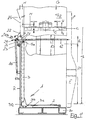
In der Fig. 2 befindet sich die Preßplatte C in der
Position ' Ballen fertig' im Preßbereich P. Die Fronttür F
ist geöffnet, die Schubstange 12 bewegt sich in
Pfeilrichtung O und schiebt dabei die Führungsteile 8 und 9
in Richtung Rückwand R, der geführte Druckbolzen 7
schwenkt gleichzeitig das Schwenkstück 4 mitsamt dem Mitnahmebolzen
6 in Pfeilrichtung Y durch den Durchbruch D in
die Rückwand R, in die Position -Auswerfen-, ein. Die seitlich
vom Durchbruch D außen an der Rückwand R vorgesehene
Führungsbahn 15 begrenzt die Schwenkbewegung des Schwenkstückes
4 so, daß der Mitnahmebolzen 6 in der in der Nut N
entlang laufenden Bewegungslinie MB des Endbereiches M' des
Mitnehmers M liegt.
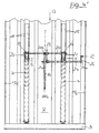
In der Fig. 3 ist der Arbeitsschritt'Auswerfen' gezeigt.
Die Preßplatte C mitsamt dem Mitnehmer M bewegt sich in
Pfeilrichtung U nach oben. Der Endbereich M' des Mitnehmers
M untergreift dabei den Mitnahmebolzen 6, wodurch
die Zugstange 3 einschließlich der Hubplatte 2 angehoben
werden. Die Hubplatte 2 schwenkt in Richtung Türöffnung und
der Ballen A wird in Pfeilrichtung W aus dem Preßbereich P
des Schachtes S ausgeworfen und kippt auf eine zuvor
positionierte, hier nicht dargestellte Transportpalette.
In spezieller Ausbildung ist hier das untere Ende der
Zugstange 3 mit einer horizontal und in Richtung Hubplatte
2 zeigenden Nase 3c ausgestattet, die den Auswurf
des Ballens A wesentlich beschleunigt.
Der während der Aufwärtsbewegung der Preßplatte C an der
Führungsbahn 15 entlang gleitende Druckbolzen 7 wird durch
den schräg nach außen verlaufenden oberen Teilbereich der
Führungsbahn 15 in Pfeilrichtung Z2 gedrückt und zieht
dabei gleichzeitig den Mitnahmebolzen 6 von dem Endbereich
M' des Mitnehmers M herunter und drückt zudem das
obere Führungsteil 8 mitsamt dem unteren Führungsteil 9
nach hinten in deren Ausgangsposition Z1. Die Hubplatte 2
mit Zugstange 3 und das an letzterem 3 befestigte
Schwenkteil 4 fallen nach unten in deren Ausgangslage gemäß
der Fig. 1 zurück, dabei kann ein an einem der Teile der
besagten Verbindungseinheit angreifendes Dämpfungselement,
vorzugsweise eine mit dem Druckbolzen7 verbundene Gasdruckfeder
18, die Fallgeschwindigkeit und den Aufprall bremsen
bzw. dämpfen.Novel and still essential in the present application, moreover, that an operable by the front door F actuating means acting on the guide means 8 and 9 of the
Fig. 1 shows that with the front door F closed, the
2, the pressing plate C is in the position 'bale ready' in the pressing area P. The front door F is open, the
In Fig. 3, the step 'ejection' is shown. The press plate C together with the driver M moves in the direction of arrow U upwards. The end portion M 'of the driver M engages under the driving
The during the upward movement of the press plate C on the
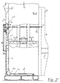
Die Fig. 4 und 6 zeigen eine abgewandelte Ausführungsvariante
des Anmeldungsgegenstandes. Die Auswurfeinrichtung 1
ist mit mehreren, kleineren Hubplatten 2, mit jeweils einer
besagten Zugstange 3 und mit jeweils einer im Bereich von
jeweils einem Durchbruch D bis D' angeordneten Verbindungseinheit
4 bis 10b , ausgestattet, wobei die von der Fronttür
F betätigten Stellmittel 12 und 14 mittels einem
Hebel 19 auf eine gemeinsame Welle 9c drehend wirken, auf
der 9c die jeweiligen unteren Führungsteile 9 fest angeordnet
sind.Figs. 4 and 6 show a modified embodiment
of the subject of the application. The
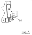
Eine Weiterbildung der Erfindung besteht noch darin, daß
die Fronttür F des Pressengehäuses G in vollständig geöffneter
Position an einen Sicherheitsschalter 20 anliegt,
wobei dieser Sicherheitsschalter 20 den Schalter für den
Preßplattenhub freigibt, und zwar in der Art und Weise,
daß erst bei vollständig geöffneter Fronttür F eine
Freigabe für die Ansteuerung des Arbeitsschrittes
'Ballenauswurf' erfolgen kann.A development of the invention still consists in that
the front door F of the press housing G in fully open
Position is applied to a
Nachfolgend wird anhand der Figuren 1' bis 5' die zweite Basislösung der Erfindung nebst Weiterbildungen beschrieben.Hereinafter, with reference to the figures 1 'to 5', the second Basic solution of the invention together with further developments described.
Bei der in den Fig. 1' bis 4' gezeigten, zur ersten
Basislösung analogen Ausführungsgrundform einer Abfallpresse,
die ein Pressengehäuse G, mit einer linken Seitenwand
S1, einer rechten Seitenwand S2, einer Rückwand R,
einer Fronttür F, mit integrierter Einfüllklappe und einer
Bodenfläche B, und einen vom Pressengehäuse G umgebenen
Schacht S, mit mindestens einem Preßbereich P und einem
darüber befindlichen Einfüllbereich E, aufweist, ist
ebenfalls auf der Bodenfläche B eine kippbare Hubplatte 2
und im Preßbereich P des Schachtes S, in der bis zur
Bodenfläche B reichenden vertikalen Nut N der Rückwand R,
eine mit der Hubplatte 2 durch ein Scharnier 3b gelenkig
verbundene Zugstange 3 angeordnet, die nach der
vorliegenden weiteren neuen Bauart mit ihrem oberen Ende
bis in den Einfüllbereich E reicht und dort mit einem nach
außen ragenden mechanischen Führungsmittel verbunden ist.
Das Wesentliche dieser zweiten neuen Konstruktionsvariante,
der zweiten Basislösung gemäß Patentanspruch 2,
liegt dabei vor allem darin, daß anstelle einer Gestängeführung
jetzt nur noch das mechanisch wirkende Führungsmittel
als zweiarmiger Schwenkhebel 21 ausgebildet und
über die Koppelstange 23 der Schubstange 12 in Verbindung
mit einem Querriegel (Verbindungsstange 25), dem Rückwandanschlag
22 und den Führungsbahnen 15 an der Pressenrückwand
R in seiner Ein- und Ausfahrbewegung steuerbar
ist. Der Ballenauswurfvorgang läuft vom Prinzip her auch
bei der zweiten neuen Lösung gleichermaßen ab, wie bei der
ersten neuen Basislösung und ergibt sich zudem aus den
zugehörigen Figuren 1 bis 5 in Verbindung mit den voranstehenden,
zugehörigen Beschreibungsteilen sowie den
betreffenden Positionen aus der Bezugszeichenliste.In the one shown in Figs. 1 'to 4', the first
Basic solution analogue execution form of a waste press,
a press housing G, with a left side wall
S1, a right side wall S2, a rear wall R,
a front door F, with integrated filler flap and a
Bottom surface B, and one of the press housing G surrounded
Shaft S, with at least one pressing area P and a
overlying filling area E, has
also on the bottom surface B a tiltable lifting plate. 2
and in the pressing region P of the shaft S, in the up to the
Bottom surface B reaching vertical groove N of the rear wall R,
one hinged to the
Ein weiteres sehr wesentliches Merkmal besteht bei der
zweiten Basislösung der Erfindung noch darin, daß das
unerwünschte Vorkippen der Stößelplatte bei geöffneter
Fronttür unter dem Zug des Ballenauswurfes, nunmehr
erstmals dadurch verhindert wird, daß entsprechend
Fig. 4' und 5' beidseits an den Innenwandungen S1 und S2
des Preßschachtes S Führungsschienen 26 und hierzu korrespondierend
Gleitklötze 27 an der Preßplatte C angeordnet
sind. Hierdurch erhält die bei geschlossener Fronttür F an
deren seitlichen Rahmenteilen F1 abgestützte Preßplatte C
nun auch eine sichere Führung in Richtung auf die geöffnete
Fronttür F hin, wenn letztere zum Auswerfen des fertigen
Ballens aufgeschwenkt ist.Another very important feature is the
second basic solution of the invention is that the
unwanted Vorkippen the plunger plate with open
Front door under the train of the ball ejection, now
is first prevented by that accordingly
Fig. 4 'and 5' on both sides of the inner walls S1 and S2
of the press shaft S guide rails 26 and corresponding thereto
Diese Weiterbildung ist aber auch bei einer Abfallpresse
nach der bereits weiter vorn beschriebenen ersten Basislösung
anwendbar. Ebenso kann der mit der erst genannten
Ausführungsvariante beschriebene Sicherheitsschalter 20
auch an nach der zweiten Basislösung aufgebauten Abfallpressen
eingesetzt werden.This development is also in a waste press
after the first basic solution described earlier
applicable. Likewise, with the first mentioned
Embodiment described
In dem vorstehenden Beschreibungsteil nicht weiter beschriebene Positionsangaben aus den Zeichnungen bzw. der Bezugszeichenliste sind als identisch mit den Angaben zur weiter vorn beschriebenen ersten Basislösung anzusehen.In the above description part no further described position information from the drawings or the List of reference numerals are to be identical to the information on to look at the first basic solution described above.
Alle in der vorstehenden Beschreibung erwähnten sowie auch die nur allein aus den Zeichnungen entnehmbaren Merkmale sind weitere Bestandteile der Erfindung, auch wenn sie nicht besonders hervorgehoben und insbesondere nicht in den Ansprüchen genannt sind. All mentioned in the above description as well as the features that can only be seen from the drawings are further components of the invention, even if they not particularly highlighted and especially not in the claims are mentioned.
- 11
- Auswurfeinrichtungejection means
- 22
- Hubplatte (Hubplatten)Lifting plate (lifting plates)
- 33
- Zugstangepull bar
- 3a3a
- unteres Ende (gelenkig mit Pos. 2 verbunden)lower end (hinged to Pos. 2)
- 3b3b
- Scharnierhinge
- 3c3c
- Nasenose
- 3d3d
- Schenkelleg
- 44
- Schwenkstückswivel mount
- 55
- Wellewave
- 5a5a
- Anlenkpunkt (von Pos. 3 an Pos. 21)Linkage point (from Pos. 3 to Pos. 21)
- 66
- Mitnahmebolzendriving pins
- 77
- Druckbolzenpushpin
- 88th
- Oberes FührungsteilUpper management part
- 8a, 8b8a, 8b
- Schenkelleg
- 8c8c
- Wellewave
- 8d8d
- LanglochLong hole
- 99
- unteres Führungsteillower part of the management
- 9a, 9b9a, 9b
- Schenkelleg
- 9c9c
- Wellewave
- 9d9d
- Stiftpen
- 9e9e
- Zapfen spigot
- 1010
- Führungsnutguide
- 10a10a
- oberer Abschnittupper section
- 10b10b
- unterer Abschnittlower section
- 1212
- Schubstangepushrod
- 1313
- Druckfedercompression spring
- 1414
- Strebestrut
- 1515
- Führungsbahnguideway
- 1616
- StabRod
- 1717
- Mechanische VerrieglungseinheitMechanical locking unit
- 17a17a
- Fronttür-VerschlußFront door closure
- 1818
- Dämpfungselement (vorzugsweise Gasdruckfeder)Damping element (preferably gas spring)
- 18a18a
- gehäuseseitige Anlenkunghousing-side linkage
- 1919
- Hebellever
- 2020
- Sicherheitsschaltersafety switch
- 2121
- Schwenkhebelpivoting lever
- 21a21a
- Ansatz (für Anlenkung von Pos. 18)Approach (for articulation of item 18)
- 2222
- Rückwandanschlag und MitnehmerRear wall stop and driver
- 2323
- Koppelstangecoupling rod
- 23a23a
- Lagerungstorage
- 2424
- starrer Hebelarmrigid lever arm
- 2525
- Verbindungsstange (von Pos. 18 und Pos. 21a)Connecting rod (from pos. 18 and pos. 21a)
- 2626
- Führungsschienenguide rails
- 2727
- Gleitklotzslide block
- AA
- Ballen (fertig gepreßt und verschnürt) Bales (finished pressed and tied)
- BB
- Bodenflächefloor area
- CC
- Preßplattepress plate
- D, D'D, D '
- Durchbrüchebreakthroughs
- Ee
- Einfüllbereichfilling area
- FF
- Fronttür (mit integrierter Einfüllklappe)Front door (with integrated filler flap)
- F1F1
- Rahmen der TürFrame of the door
- GG
- Pressengehäusepress housing
- MM
- Mitnehmertakeaway
- M'M '
- Endbereichend
- MBMB
- Bewegungslinie des Endbereiches M' vom Mitnehmer MLine of movement of the end portion M 'of the driver M
- NN
- Nutgroove
- OO
- Pfeilrichtung (Fronttür offen)Arrow direction (front door open)
- PP
- Preßbereichpress area
- SS
- Schacht der PresseShaft of the press
- RR
- Rückwandrear wall
- S1, S2S1, S2
- Seitenwändeside walls
- U, V, WAND MANY MORE
- Pfeilrichtungenarrow directions
- YY
- Pfeilrichtung (Position 'Auswerfen')Arrow direction (position 'Eject')
- ZZ
- Pfeilrichtung (Geschlossen)Arrow direction (closed)
- Z1Z1
- Pfeilrichtung (Position 'Ruhe')Arrow direction (position 'rest')
- Z2Z2
- Pfeilrichtungarrow
Claims (12)
- Waste material press with ejector equipment for bales, in which at least one tiltable stroke plate (2) is arranged on or in a base surface (B) of a shaft (S) formed by a press housing (G) and at least one pull rod (3), which is pivotably connected with the stroke plate (2), of the ejector equipment (1) is arranged in the press region (P) of the shaft (S) at or in a rear wall (R), as well as a coupling member at least temporarily connecting the pull rod (3) and the press plate (C) and a setting means actuable by the front door (F) of the press housing (G) and acting indirectly or directly on the coupling member are provided, characterised in that the coupling member temporarily transmitting the movement of the press plate (C, M, M') to the tiltable stroke plate (2) of the ejector equipment (1) is constructed as a constrainedly inwardly and outwardly pivotable connecting unit (4 to 10b) which is disposed externally at the rear wall (R) of the press housing (G) and projects partly through a passage (D) formed in the rear wall (R) and which temporarily engages the press plate (C, M, M') and additionally comprises mechanically acting guide means and pivotably engages at the upper end of the pull rod (3) and that the connecting unit (4 to 10b) inclusive of guide means is formed as a linkage guide, wherein the connecting unit (4 to 10b) consists of at least one pivot member (4), which is pivotably connected by means of a shaft (5) with the pull rod (3) and at which an entrainer pin (6) and a pressure pin (7) are additionally provided, and of a lower U-shaped guide part (9) and an upper U-shaped guide part (8), which in the region of the passage (D) are respectively pivotably mounted at the outer side of the rear wall (R) by way of a shaft (9c or 8c) and which together form a closed, positionally variable guide (10) for the pressure pin (7).
- Waste material press with ejector equipment for bales, in which at least one tiltable stroke plate (2) is arranged on or in a base surface (B) of a shaft (S) formed by a press housing (G) and at least one pull rod (3), which is pivotably connected with the stroke plate (2), of the ejector equipment (1) is arranged in the press region (P) of the shaft (S) at or in a rear wall (R), as well as a coupling member at least temporarily connecting the pull rod (3) and the press plate (C) and a setting means actuable by the front door (F) of the press housing (G) and acting indirectly or directly on the coupling member are provided, characterised in that the coupling member temporarily transmitting the movement of the press plate (C, M, M') to the tiltable stroke plate (2) of the ejector equipment (1) is constructed as a constrainedly inwardly and outwardly pivotable connecting unit (4 to 10b) which is disposed externally at the rear wall (R) of the press housing (G) and projects partly through a passage (D) formed in the rear wall (R) and which temporarily engages the press plate (C, M, M') and additionally comprises mechanically acting guide means and pivotably engages at the upper end of the pull rod (3) and the coupling member is provided as a pivot lever mechanism, wherein the mechanically acting guide means is constructed as a double-arm pivot lever (21) and is so arranged that the lever (21) is controllable in its inward and outward movement by way of the coupling rod (23) of the push rod (12) in conjunction with a transverse lock (connecting rod 25), the rear wall abutment (22) and the guide tracks (15) at the press rear wall (R).
- Waste material press with ejector equipment for bales according to claim 1, characterised in that the said connecting unit (4 to 10b) and passage (D) are arranged above the press region (P) in the filling region (E) of the shaft (S) externally at or partly in the rear wall (R) and that at least one guide track (15) acting on parts of the connecting unit (4 to 10b) and extending at an inclination outwardly in its upper part region as seen in upward direction is provided laterally of the passage (D) externally at the rear wall (R).
- Waste material press with ejector equipment for bales according to at least one of claims 1 to 3, characterised in that the setting means influenced by the movement of the front door (F) are constructed as a push rod (12) guided in or at a side wall (S1 or S2) of the press housing (G) and disposed under spring pressure (13) and a strut (14) or lever arm (24) connecting the push rod (12) with one of the guide means of the connecting unit.
- Waste material press with ejector equipment for bales; according to at least one of claims 1 to 4, characterised in that the setting means influenced by the movement of the front door (F) are constructed as a push rod (12) guided in or at a side wall (S1 or S2) of the press housing (G) and disposed under spring pressure (13) and a strut (14) or lever arm (24) connecting the push rod (12) with one of the guide means of the connecting unit.
- Waste material press with ejector equipment for bales according to at least one of claims 1, 3, 4 and 5, characterised in that the ejector equipment (1) comprises several smaller stroke plates (2') each with a respective said pull rod (3) and a respective connecting unit arranged in the region of a respective passage (D, D', ...), wherein the setting means (12 and 14) actuated by the front door (F) rotationally act by means of a lever (19) on a common shaft (9c), on which shaft (9c) the respective lower guide parts (9) are fixedly arranged.
- Waste material press with ejector equipment for bales according to at least one of claims 1 to 5, characterised in that the lower end of the pull rod (3) is equipped with a horizontal lug (3c) directed towards the stroke plate (2).
- Waste material press with ejector equipment for bales according to at least one of claims 1 to 7, characterised in that a damping element, preferably a gas pressure spring (18), which is supported relative to the rear wall (R) of the press housing (G), engages at one of the parts of the said connecting unit, particularly at the pressure pin (6) or at the connecting rod (25).
- Waste material press with ejector equipment for bales according to at least one of claims 1 to 8, characterised in that guide rails (26) and slide blocks (27) corresponding therewith are arranged at the press plate (C) at both sides at the inner walls (S1 and S2) of the press shaft (S).
- Waste material press according to claim 9, characterised in that the guide rails (26) are constructed as flat bar webs, which extend in press direction and are welded in place, and are seated in the rear shaft third as seen from the front door (F).
- Waste material press with ejector equipment for bales according to at least one of claims 1 to 10, characterised in that the front door (F) of the press housing (G) bears against a safety switch (20) in the completely open position.
- Waste material press with ejector equipment for bales according to claim 2, characterised by a constructional design in correspondence with Figs. 1' to 5' in connection with the detail definition data of the reference numeral list.
Applications Claiming Priority (4)
| Application Number | Priority Date | Filing Date | Title |
|---|---|---|---|
| DE1997138060 DE19738060A1 (en) | 1997-09-01 | 1997-09-01 | Press for compacting offcuts with bale ejection device |
| DE19738060 | 1997-09-01 | ||
| DE19755644 | 1997-12-15 | ||
| DE1997155644 DE19755644A1 (en) | 1997-09-01 | 1997-12-15 | Ejection device for waste balers |
Publications (3)
| Publication Number | Publication Date |
|---|---|
| EP0899088A2 EP0899088A2 (en) | 1999-03-03 |
| EP0899088A3 EP0899088A3 (en) | 1999-03-17 |
| EP0899088B1 true EP0899088B1 (en) | 2005-11-02 |
Family
ID=26039588
Family Applications (1)
| Application Number | Title | Priority Date | Filing Date |
|---|---|---|---|
| EP98116417A Expired - Lifetime EP0899088B1 (en) | 1997-09-01 | 1998-08-31 | Waste compactor with a bale ejecting apparatus |
Country Status (4)
| Country | Link |
|---|---|
| US (1) | US6000325A (en) |
| EP (1) | EP0899088B1 (en) |
| AT (1) | ATE308416T1 (en) |
| DE (1) | DE59813155D1 (en) |
Cited By (1)
| Publication number | Priority date | Publication date | Assignee | Title |
|---|---|---|---|---|
| DE102009053134B4 (en) | 2009-11-05 | 2013-09-19 | Maschinenfabrik Bermatingen Gmbh & Co. Kg | baler |
Families Citing this family (4)
| Publication number | Priority date | Publication date | Assignee | Title |
|---|---|---|---|---|
| FR2966448A1 (en) * | 2010-10-20 | 2012-04-27 | Plastic Omnium Cie | Waste compactor for use in waste collection tank assembly in waste collection container located on public highway, has set of moving units located on outer side of compaction chamber |
| FR2966449A1 (en) * | 2010-10-20 | 2012-04-27 | Plastic Omnium Cie | Waste compactor, has return plates placed in compaction chamber and separated from body of door, where return plates are arranged for movement toward opening of chamber during opening of door |
| TWI473705B (en) * | 2012-05-22 | 2015-02-21 | Ching Rei Mechanics Co Ltd | Small-sized compressor structure and the compression method thereof |
| US9764522B2 (en) * | 2013-05-16 | 2017-09-19 | John Desser | Clothing compression press and method of compressing clothing |
Family Cites Families (11)
| Publication number | Priority date | Publication date | Assignee | Title |
|---|---|---|---|---|
| US3728959A (en) * | 1970-10-27 | 1973-04-24 | W Fredrickson | Baler |
| US3916781A (en) * | 1973-02-16 | 1975-11-04 | American Environmental Prod | Bale ejection system |
| US3955492A (en) * | 1975-03-10 | 1976-05-11 | Lo-Lift Corporation | Baler |
| DE2630906A1 (en) * | 1976-07-09 | 1978-01-12 | Schleicher Co Feinwerktech | Refuse compacting press assembly - has lever mechanism to tilt bale out of press chamber and onto palet |
| SE418476B (en) * | 1978-05-02 | 1981-06-09 | Electrolux Ab | DEVICE FOR BALL PRESSURES OR SIMILAR PRESSURES |
| US4232599A (en) * | 1978-10-19 | 1980-11-11 | J. V. Manufacturing & Welding, Inc. | Waste paper compacter with front access features |
| US4182236A (en) * | 1978-11-30 | 1980-01-08 | Piqua Engineering, Inc. | Vertical baler with improved material hold-down and bale ejecting means |
| US4311092A (en) * | 1979-12-19 | 1982-01-19 | The American Baler Company | Low-profile vertical baling machine |
| US5044271A (en) * | 1990-03-29 | 1991-09-03 | Marathon Equipment Company | Compactor door and interlock |
| SE467771B (en) * | 1991-07-09 | 1992-09-14 | Orwak Ab | Landfill |
| GB9302058D0 (en) * | 1993-02-03 | 1993-03-24 | Milldale Ltd | A baling press |
-
1998
- 1998-08-31 DE DE59813155T patent/DE59813155D1/en not_active Expired - Fee Related
- 1998-08-31 AT AT98116417T patent/ATE308416T1/en not_active IP Right Cessation
- 1998-08-31 US US09/143,934 patent/US6000325A/en not_active Expired - Fee Related
- 1998-08-31 EP EP98116417A patent/EP0899088B1/en not_active Expired - Lifetime
Cited By (2)
| Publication number | Priority date | Publication date | Assignee | Title |
|---|---|---|---|---|
| DE102009053134B4 (en) | 2009-11-05 | 2013-09-19 | Maschinenfabrik Bermatingen Gmbh & Co. Kg | baler |
| DE102009053134C5 (en) * | 2009-11-05 | 2018-01-25 | Maschinenfabrik Bermatingen Gmbh & Co. Kg | baler |
Also Published As
| Publication number | Publication date |
|---|---|
| EP0899088A2 (en) | 1999-03-03 |
| ATE308416T1 (en) | 2005-11-15 |
| DE59813155D1 (en) | 2005-12-08 |
| US6000325A (en) | 1999-12-14 |
| EP0899088A3 (en) | 1999-03-17 |
Similar Documents
| Publication | Publication Date | Title |
|---|---|---|
| DE2344698C2 (en) | Device for compacting garbage | |
| EP0899088B1 (en) | Waste compactor with a bale ejecting apparatus | |
| DE10251516B4 (en) | baler | |
| DE2340419A1 (en) | SAFETY SKI BINDING | |
| DE2749486C2 (en) | ||
| DE3538076A1 (en) | LATCH CLOSURE | |
| DE60122760T2 (en) | A SUNROOF ASSEMBLY FOR A VEHICLE AND A VEHICLE PROVIDED WITH SUCH A SUNROOF DESIGN | |
| DE19738060A1 (en) | Press for compacting offcuts with bale ejection device | |
| DE2317553C2 (en) | Device for opening the lid when emptying containers, for example garbage cans | |
| DE3319527A1 (en) | Safety device for a hydraulic downstroke press | |
| EP1171283B1 (en) | Baling press comprising a tiltable compacting container, and method for operating the same | |
| DE2156572A1 (en) | DEVICE FOR LOCKING A CHANGE CONTAINER WITH A MUELL PRESS | |
| DE2917118C2 (en) | ||
| EP1167005B1 (en) | Baling press | |
| EP0596305B1 (en) | Closing device | |
| DE2442145C3 (en) | Garbage container with a device for compacting garbage | |
| DE2501154C2 (en) | Device for compacting garbage with a PreBplatte | |
| DE19952483C1 (en) | Locking device for adjacent lifting and tipping devices of refuse collection vehicle has locking element coupled for operation via pivot arm of one lifting and tipping device | |
| EP1179413B1 (en) | Baling press | |
| DE10154784B4 (en) | Tamping box for the compression of coking coal | |
| DE4205046A1 (en) | CLOSING MECHANISM | |
| DE10029440A1 (en) | Press has lower pivotable flap part that moves upper part up via pull chords when opened; upper part can be released from connection to lower part for opening when lower part closed | |
| DD209610A1 (en) | LOCKING AND UNLOADING DEVICE FOR ONE PLIER | |
| DE102010037655A1 (en) | Refuse collection vehicle | |
| DE4041528A1 (en) | PRESS FOR THE PRODUCTION OF BURNED BALLS |
Legal Events
| Date | Code | Title | Description |
|---|---|---|---|
| PUAI | Public reference made under article 153(3) epc to a published international application that has entered the european phase |
Free format text: ORIGINAL CODE: 0009012 |
|
| PUAL | Search report despatched |
Free format text: ORIGINAL CODE: 0009013 |
|
| AK | Designated contracting states |
Kind code of ref document: A2 Designated state(s): AT DE DK ES FR GB SE |
|
| AX | Request for extension of the european patent |
Free format text: AL;LT;LV;MK;RO;SI |
|
| AK | Designated contracting states |
Kind code of ref document: A3 Designated state(s): AT BE CH CY DE DK ES FI FR GB GR IE IT LI LU MC NL PT SE |
|
| AX | Request for extension of the european patent |
Free format text: AL;LT;LV;MK;RO;SI |
|
| 17P | Request for examination filed |
Effective date: 19990916 |
|
| AKX | Designation fees paid |
Free format text: AT DE DK ES FR GB SE |
|
| 17Q | First examination report despatched |
Effective date: 20020731 |
|
| GRAP | Despatch of communication of intention to grant a patent |
Free format text: ORIGINAL CODE: EPIDOSNIGR1 |
|
| GRAS | Grant fee paid |
Free format text: ORIGINAL CODE: EPIDOSNIGR3 |
|
| GRAA | (expected) grant |
Free format text: ORIGINAL CODE: 0009210 |
|
| AK | Designated contracting states |
Kind code of ref document: B1 Designated state(s): AT DE DK ES FR GB SE |
|
| PG25 | Lapsed in a contracting state [announced via postgrant information from national office to epo] |
Ref country code: GB Free format text: LAPSE BECAUSE OF FAILURE TO SUBMIT A TRANSLATION OF THE DESCRIPTION OR TO PAY THE FEE WITHIN THE PRESCRIBED TIME-LIMIT Effective date: 20051102 |
|
| REG | Reference to a national code |
Ref country code: GB Ref legal event code: FG4D Free format text: NOT ENGLISH |
|
| REF | Corresponds to: |
Ref document number: 59813155 Country of ref document: DE Date of ref document: 20051208 Kind code of ref document: P |
|
| PG25 | Lapsed in a contracting state [announced via postgrant information from national office to epo] |
Ref country code: SE Free format text: LAPSE BECAUSE OF FAILURE TO SUBMIT A TRANSLATION OF THE DESCRIPTION OR TO PAY THE FEE WITHIN THE PRESCRIBED TIME-LIMIT Effective date: 20060202 Ref country code: DK Free format text: LAPSE BECAUSE OF FAILURE TO SUBMIT A TRANSLATION OF THE DESCRIPTION OR TO PAY THE FEE WITHIN THE PRESCRIBED TIME-LIMIT Effective date: 20060202 |
|
| PG25 | Lapsed in a contracting state [announced via postgrant information from national office to epo] |
Ref country code: ES Free format text: LAPSE BECAUSE OF FAILURE TO SUBMIT A TRANSLATION OF THE DESCRIPTION OR TO PAY THE FEE WITHIN THE PRESCRIBED TIME-LIMIT Effective date: 20060213 |
|
| GBV | Gb: ep patent (uk) treated as always having been void in accordance with gb section 77(7)/1977 [no translation filed] |
Effective date: 20051102 |
|
| PLBE | No opposition filed within time limit |
Free format text: ORIGINAL CODE: 0009261 |
|
| STAA | Information on the status of an ep patent application or granted ep patent |
Free format text: STATUS: NO OPPOSITION FILED WITHIN TIME LIMIT |
|
| 26N | No opposition filed |
Effective date: 20060803 |
|
| EN | Fr: translation not filed | ||
| PG25 | Lapsed in a contracting state [announced via postgrant information from national office to epo] |
Ref country code: FR Free format text: LAPSE BECAUSE OF FAILURE TO SUBMIT A TRANSLATION OF THE DESCRIPTION OR TO PAY THE FEE WITHIN THE PRESCRIBED TIME-LIMIT Effective date: 20061222 |
|
| PGFP | Annual fee paid to national office [announced via postgrant information from national office to epo] |
Ref country code: DE Payment date: 20070823 Year of fee payment: 10 |
|
| PG25 | Lapsed in a contracting state [announced via postgrant information from national office to epo] |
Ref country code: AT Free format text: LAPSE BECAUSE OF NON-PAYMENT OF DUE FEES Effective date: 20060831 |
|
| PG25 | Lapsed in a contracting state [announced via postgrant information from national office to epo] |
Ref country code: FR Free format text: LAPSE BECAUSE OF FAILURE TO SUBMIT A TRANSLATION OF THE DESCRIPTION OR TO PAY THE FEE WITHIN THE PRESCRIBED TIME-LIMIT Effective date: 20051102 |
|
| PG25 | Lapsed in a contracting state [announced via postgrant information from national office to epo] |
Ref country code: DE Free format text: LAPSE BECAUSE OF NON-PAYMENT OF DUE FEES Effective date: 20090303 |