EP0898381B1 - Verfahren zur Entzerrung und Entzerrer in einem OFDM-Empfänger - Google Patents
Verfahren zur Entzerrung und Entzerrer in einem OFDM-Empfänger Download PDFInfo
- Publication number
- EP0898381B1 EP0898381B1 EP98306336A EP98306336A EP0898381B1 EP 0898381 B1 EP0898381 B1 EP 0898381B1 EP 98306336 A EP98306336 A EP 98306336A EP 98306336 A EP98306336 A EP 98306336A EP 0898381 B1 EP0898381 B1 EP 0898381B1
- Authority
- EP
- European Patent Office
- Prior art keywords
- predetermined number
- channel
- scattered pilot
- channel characteristic
- scattered
- Prior art date
- Legal status (The legal status is an assumption and is not a legal conclusion. Google has not performed a legal analysis and makes no representation as to the accuracy of the status listed.)
- Expired - Lifetime
Links
Images
Classifications
-
- H—ELECTRICITY
- H04—ELECTRIC COMMUNICATION TECHNIQUE
- H04L—TRANSMISSION OF DIGITAL INFORMATION, e.g. TELEGRAPHIC COMMUNICATION
- H04L5/00—Arrangements affording multiple use of the transmission path
- H04L5/003—Arrangements for allocating sub-channels of the transmission path
- H04L5/0048—Allocation of pilot signals, i.e. of signals known to the receiver
-
- H—ELECTRICITY
- H04—ELECTRIC COMMUNICATION TECHNIQUE
- H04B—TRANSMISSION
- H04B1/00—Details of transmission systems, not covered by a single one of groups H04B3/00 - H04B13/00; Details of transmission systems not characterised by the medium used for transmission
- H04B1/06—Receivers
- H04B1/10—Means associated with receiver for limiting or suppressing noise or interference
-
- H—ELECTRICITY
- H04—ELECTRIC COMMUNICATION TECHNIQUE
- H04B—TRANSMISSION
- H04B7/00—Radio transmission systems, i.e. using radiation field
- H04B7/01—Reducing phase shift
-
- H—ELECTRICITY
- H04—ELECTRIC COMMUNICATION TECHNIQUE
- H04L—TRANSMISSION OF DIGITAL INFORMATION, e.g. TELEGRAPHIC COMMUNICATION
- H04L25/00—Baseband systems
- H04L25/02—Details ; arrangements for supplying electrical power along data transmission lines
- H04L25/0202—Channel estimation
- H04L25/0224—Channel estimation using sounding signals
- H04L25/0226—Channel estimation using sounding signals sounding signals per se
-
- H—ELECTRICITY
- H04—ELECTRIC COMMUNICATION TECHNIQUE
- H04L—TRANSMISSION OF DIGITAL INFORMATION, e.g. TELEGRAPHIC COMMUNICATION
- H04L25/00—Baseband systems
- H04L25/02—Details ; arrangements for supplying electrical power along data transmission lines
- H04L25/0202—Channel estimation
- H04L25/0224—Channel estimation using sounding signals
- H04L25/0228—Channel estimation using sounding signals with direct estimation from sounding signals
- H04L25/023—Channel estimation using sounding signals with direct estimation from sounding signals with extension to other symbols
- H04L25/0232—Channel estimation using sounding signals with direct estimation from sounding signals with extension to other symbols by interpolation between sounding signals
-
- H—ELECTRICITY
- H04—ELECTRIC COMMUNICATION TECHNIQUE
- H04L—TRANSMISSION OF DIGITAL INFORMATION, e.g. TELEGRAPHIC COMMUNICATION
- H04L25/00—Baseband systems
- H04L25/02—Details ; arrangements for supplying electrical power along data transmission lines
- H04L25/03—Shaping networks in transmitter or receiver, e.g. adaptive shaping networks
- H04L25/03006—Arrangements for removing intersymbol interference
- H04L25/03159—Arrangements for removing intersymbol interference operating in the frequency domain
-
- H—ELECTRICITY
- H04—ELECTRIC COMMUNICATION TECHNIQUE
- H04L—TRANSMISSION OF DIGITAL INFORMATION, e.g. TELEGRAPHIC COMMUNICATION
- H04L25/00—Baseband systems
- H04L25/02—Details ; arrangements for supplying electrical power along data transmission lines
- H04L25/03—Shaping networks in transmitter or receiver, e.g. adaptive shaping networks
- H04L25/03006—Arrangements for removing intersymbol interference
- H04L2025/0335—Arrangements for removing intersymbol interference characterised by the type of transmission
- H04L2025/03375—Passband transmission
- H04L2025/03414—Multicarrier
-
- H—ELECTRICITY
- H04—ELECTRIC COMMUNICATION TECHNIQUE
- H04L—TRANSMISSION OF DIGITAL INFORMATION, e.g. TELEGRAPHIC COMMUNICATION
- H04L25/00—Baseband systems
- H04L25/02—Details ; arrangements for supplying electrical power along data transmission lines
- H04L25/03—Shaping networks in transmitter or receiver, e.g. adaptive shaping networks
- H04L25/03006—Arrangements for removing intersymbol interference
- H04L2025/03433—Arrangements for removing intersymbol interference characterised by equaliser structure
- H04L2025/03439—Fixed structures
- H04L2025/03522—Frequency domain
-
- H—ELECTRICITY
- H04—ELECTRIC COMMUNICATION TECHNIQUE
- H04L—TRANSMISSION OF DIGITAL INFORMATION, e.g. TELEGRAPHIC COMMUNICATION
- H04L5/00—Arrangements affording multiple use of the transmission path
- H04L5/0001—Arrangements for dividing the transmission path
- H04L5/0003—Two-dimensional division
- H04L5/0005—Time-frequency
- H04L5/0007—Time-frequency the frequencies being orthogonal, e.g. OFDM(A) or DMT
Definitions
- the present invention relates in general to an equalizer and to an equalizing method for compensating for channel distortion in a receiver for receiving a signal transmitted by an orthogonal frequency division multiplexing (OFDM) method.
- OFDM orthogonal frequency division multiplexing
- OFDM is a type of multiple carrier modulating method for transmitting a digital signal.
- data is carried by a plurality of sub-carriers and transmitted in parallel during a long symbol period, using a frequency band of the same width as that used for transmitting single carrier data. Since a symbol is determined in a frequency domain in the OFDM method, an equalizer used in the frequency domain is required for compensating for channel distortion of the received symbol.
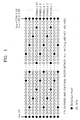
- scattered pilots are transmitted in the OFDM method. However, the scattered pilots are not transmitted through fixed sub channels, but are transmitted through different sub channels in every symbol, having a predetermined pattern, as shown in Figure 1.
- the scattered pilots are repeated using four symbols as one period. Since the scattered pilots are transmitted through the first and final sub channels in a 12 sub channel period, making a second starting point of every symbol different, the characteristics of all the sub channels are estimated by finding out positions to which the scattered pilots are transmitted, calculating estimated values according to all the characteristics of the sub channel, and obtaining the characteristics of the data sub channels between the scattered pilots by interpolating the estimated values of adjacent pilots.
- the distance between the scattered pilots becomes 11 sub channels, a compensation error becomes larger when frequency distortion is generated.
- a precise filter is required as an interpolating filter since there are 11 sub channels between the scattered pilots.
- the document FR 2,743,967 describes a quincunxial arrangement of the scattered pilots, of which a fictions pilot symbol is obtained by grouping together each of the extracted scattered pilots which belong to the quincunxial arrangement.
- an equalizing method for compensating for channel distortion in a plurality of carriers transmitted through a plurality of sub channels using scattered pilots having a period of a first predetermined number of symbols comprising the steps of (a) extracting scattered pilots from a plurality of received carriers and estimating a channel characteristic value in the position of an extracted scattered pilot (b) providing a channel characteristic value in a scattered pilot position having a period of a third predetermined number of sub channels by updating the channel characteristic value of the scattered pilot position of a period having a second predetermined number of sub channels in every symbol, and by maintaining a previous channel characteristic value in the remaining scattered pilots, (c) providing the characteristic values of all the sub channels by estimating the characteristics of a sub channel through which data between scattered pilots is transmitted using the channel characteristic values in the scattered pilot position having the period of the third predetermined number of sub channels, and (d) compensating for the channel distortion of the received plurality of carriers on the basis of all the sub channel characteristic values.
- an equalizer for an OFDM receiver for receiving a plurality of carriers including a scattered pilot having a period of a first predetermined number of symbols through a plurality of sub channels, comprising:
- STEP 1 a channel characteristic value in the position of an extracted scattered pilot is estimated by revealing which symbol is received among four symbols and extracting the scattered pilot from the received symbol.
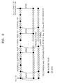
- STEP 2 a channel characteristic value in the position of the scattered pilot having a three sub channel period as shown in Figure 2 is obtained by updating the sub channel through which the scattered pilot is transferred in every symbol into a new value and maintaining the updated value over the next three symbol interval.
- an upper first symbol shows channel characteristics in the position of scattered pilots having a three sub channel period applied to the symbols starting from a received fifth symbol.
- the sub channel through which the scattered pilot is transmitted in every symbol is updated to a new value. Over the next three symbol intervals, the updated value is maintained.
- the sub channel through which each scattered pilot is transmitted is used for transferring the scattered pilot once every four symbols, when the characteristic of the sub channel through which the scattered pilot is transferred in every symbol is updated to a new value and the value is maintained over four symbols, it is possible to adapt to the change of time of the channel.
- STEP 3 the characteristics of two sub channels through which data between two adjacent scattered pilots are transmitted is estimated by interpolating the channel characteristic value of the position of the scattered pilot estimated in STEP 2.
- the characteristics of three sub channels are calculated in the same manner, considering that the characteristic of a sub channel through which the scattered pilot is transmitted is the same as that of the sub channel through which the following two data are transmitted when the characteristics of the sub channel hardly changes.
- the characteristics of the two sub channels through which data are transmitted are calculated by a linear interpolation.
- a windowed finite impulse response (FIR) filter having a higher interpolation performance is used.
- the structure of the equalizer is simple when constant interpolation or linear interpolation are used.
- the accuracy is lower than in the interpolating method according to the windowed FIR filter.
- the interpolating method by the windowed FIR filter is used, the accuracy becomes higher.
- an error may be generated in the starting portion of the symbol since the position of the scattered pilot is continuous at the end and the start of the symbol. Therefore, the constant interpolation or the linear interpolation is used at the starting portion of the symbol.
- the interpolation by the windowed FIR filter is used in the other portions. Accordingly, equalizing performance is improved.
- STEP 4 to estimate the characteristics of the sub channels through which data are transmitted means that the characteristics of all the sub channels are known. Therefore, the amplitude and phase distortion, i.e., the channel distortion, is compensated for by multiplying the transmitted sub channel data by the inverse of the characteristic of the sub channel.
- the sub channel through which a pilot is transmitted can be represented as the following equation 2.
- the amplitude characteristics and the phase characteristics of the sub channel can be obtained from the equation 3.
- R k f H k f ⁇ P k f wherein, P(f) represents a scattered pilot.
- H k f R k f P k f
- the number of sub channels obtained from the scattered pilots of a modified distribution shown in Figure 2 is 6816/3.
- the characteristics of the 6816x2/3 data channel are obtained by an interpolation using the characteristics of the sub channels.
- the constant interpolation or the linear interpolation is performed to every starting portion twelve carriers and an interpolation by a windowed FIR filter is performed to the other portions.
- the windowed FIR filter uses a low pass filter whose sampling frequency is three times a carrier frequency.
- the equalized output represented in the equation 8 is obtained by obtaining the characteristics of all the sub channels by the above method and multiplying the received data by the inverse of the characteristic of the sub channel.
- the windowed FIR filter can be used in order to enhance the interpolation performance.
- the equalization in the frequency domain can be performed by multiplying the received signal by the inverse of the channel characteristics value.
- the equalization becomes very simple since it has the structure of an equalizer having a one tap filter.
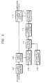
- a guard interval remover 102 removes a cyclic prefix (CP) corresponding to a guard interval from the received data.
- a guard band remover 104 performs a fast Fourier transform (FFT) on data output from the guard interval remover 102 and removes the guard band included in the fast Fourier transformed data in units of one symbol in order to convert the data into the data of a frequency domain since the data output from the guard interval remover 102 is data of a time domain.
- FFT fast Fourier transform
- each symbol is formed of 6817 carriers.
- the symbols are transmitted for a duration Ts.
- the duration Ts includes an effective symbol part interval for transmitting the 6817 carriers and a guard interval.
- a scattered pilot extractor 106 extracts the scattered pilot from data output from the guard band remover 104, namely, the 6817 carriers in every symbol in the case of an 8K mode. Since the scattered pilots have a boosted power level, the scattered pilot extractor 106 examines a correlation between the data from which the guard band has been removed and a reference sequence, and extracts the scattered pilot. Since the reference sequence is one symbol pattern data among four symbols, it is possible to find out which is the symbol received at present among the four symbols. Since the scattered pilot is repeated over a four symbol period, the position of the scattered pilot of the four symbols is automatically revealed by revealing the position of the scattered pilot of one symbol. Therefore, it is possible to correctly reveal the position of the scattered pilot of one symbol using the reference sequence by the scattered pilot extractor 106. With respect to the next three symbols, the received level value is output in the already revealed position of the scattered pilot.
- the boosted power level of the received scattered pilot is (4/3) 2 .
- the scattered pilot according to the positions of the respective scattered pilots of the four symbol period during transmission has a coordinate value of (4/3,0) or (-4/3,0). Since this coordinate value, i.e., phase information, is already revealed by a scattered pilot determiner 108, the coordinate value of the scattered pilot extracted from the scattered pilot extractor 106 is output to a channel estimator 110.
- the channel estimator 110 outputs the channel characteristic value in the position of the scattered pilot by channel estimating using a coordinate value according to the position of the scattered pilot output from the scattered pilot determiner 108. Namely, the channel estimator 110 compares the boosted level of the scattered pilot extracted by the scattered pilot extractor 106 with the original coordinate value and outputs a value (r) for compensating for the amplitude distortion and a value ( ⁇ ) for compensating for the phase distortion.
- a channel characteristic updater 112 updates the channel characteristic value of the sub channel through which each scattered pilot is transmitted into a new value in every symbol and maintains the updated value during the next three symbols. By doing so, an equalizing coefficient is updated into a new value in the scattered pilot position of the 12 sub channel distance in every symbol. The equalizing coefficients in the remaining scattered pilot positions maintain their previous values.
- the distance between the sub channels through which the scattered pilots are transmitted is two sub channels. However, the current channel characteristics of the scattered pilot are reflected by 1/4 (12 sub channel distance) in every symbol. Accordingly, it is possible to adapt to the characteristics of the channel changing as time goes by.
- a coefficient interpolator 114 performs linear interpolation, constant interpolation or windowed FIR filter interpolation on the basis of the channel characteristic value in the pilot position of the three sub channel period in which the channel characteristics of the scattered pilots are updated by a distance of 12 sub channels in every symbol provided from the channel characteristic updater 112, and outputs the interpolated coefficients in order to estimate the sub channel characteristics of the data of the two sub channels between pilots.
- a frequency domain equalizer 116 can be constructed of a filter having one tap, namely, a multiplier.
- the frequency domain equalizer 116 outputs data compensated by multiplying the data output from the guard band remover 104 by the inverse of the coefficient interpolated by the coefficient interpolator 114.
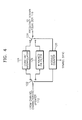
- Figure 4 is a block diagram of the coefficient interpolator 114 shown in Figure 3.
- a modulo counter 120 modulo counts the output of the channel characteristic updater 112 shown in Figure 3 according to a symbol synchronizing signal from 0 to 6816 since one symbol is comprised of 6817 effective carriers and generates a select control signal when numbers to a predetermined number (here, 11) in the starting portion of every symbol are counted.
- a divider 122 constituted of a demultiplexer outputs to a constant interpolator 124 the channel characteristic values in the starting portion of every symbol among the channel characteristic values in the scattered pilot position output from the channel characteristic updater 112 according to the select control signal output from the modulo counter 120, and outputs the remaining channel characteristic values to a windowed FIR filter 126.
- the constant interpolator 124 can be replaced by a linear interpolator.
- the windowed FIR filter 126 is constituted of a low pass filter whose sampling frequency is three times the carrier frequency.
- a selector 128 constituted of a multiplexer selects the output of the constant interpolator 124 in the case of the starting portion of a symbol according to the select control signal generated by the modulo counter 120, otherwise selects the windowed FIR filter 126, and outputs the selected signal to the frequency domain equalizer 116 shown in Figure 3.
- Figure 4 shows the divider 122 and the selector 128. However, the divider 122 may be omitted.
- the amount of calculating is reduced by reducing the distance between scattered pilots, adapting to the channel changing as time goes by.
- the structure of the interpolator employed in the equalizer described above is simple, since only the characteristics of two data sub channels are interpolated. It is possible to improve the performance of the equalizer by operating two types of interpolators.
Landscapes
- Engineering & Computer Science (AREA)
- Signal Processing (AREA)
- Computer Networks & Wireless Communication (AREA)
- Power Engineering (AREA)
- Cable Transmission Systems, Equalization Of Radio And Reduction Of Echo (AREA)
- Digital Transmission Methods That Use Modulated Carrier Waves (AREA)
Claims (16)
- Entzerrungsverfahren zum Kompensieren von Kanalverzerrung bei einer Vielzahl von Trägern, die über eine Vielzahl von Unterkanälen gesendet werden, unter Verwendung verstreuter Piloten mit einer Periode einer ersten vorgegebenen Anzahl von Symbolen, die folgenden Schritte umfassend:(a) Extrahieren (106) verstreuter Piloten aus einer Vielzahl empfangener Träger und Schätzen eines Kanalkennwerts an der Position eines extrahierten verstreuten Piloten; und des Weiteren durch die folgenden Schritte gekennzeichnet:(b) Bereitstellen (112) eines Kanalkennwerts an einer Position von verstreutem Piloten mit einer Periode einer dritten vorgegebenen Anzahl von Unterkanälen durch Aktualisieren des Kanalkennwerts der Position von verstreutem Piloten mit einer Periode einer zweiten vorgegebenen Anzahl von Unterkanälen bei jedem Symbol und durch Beibehalten eines vorherigen Kanalkennwerts bei den verbleibenden verstreuten Piloten;(c) Bereitstellen (114) der Kennwerte aller Unterkanäle durch Schätzen der Kennlinien eines Unterkanals, über den Daten zwischen verstreuten Piloten gesendet werden, unter Verwendung der Kanalkennwerte an der Position von verstreutem Piloten mit der Periode der dritten vorgegebenen Anzahl von Unterkanälen; und(d) Kompensieren (116) der Kanalverzerrung der empfangenen Vielzahl von Trägern auf der Basis aller Unterkanalkennwerte.
- Verfahren nach Anspruch 1, wobei ein aktualisierter Kanalkennwert des verstreuten Piloten der Periode der zweiten vorgegebenen Anzahl von Unterkanälen während der ersten vorgegebenen Anzahl von Symbolen in dem Schritt (b) beibehalten wird.
- Verfahren nach Anspruch 1 oder 2, wobei die Kanalkennwerte an der Position von verstreutem Piloten mit der Periode der dritten vorgegebenen Anzahl von Unterkanälen durch eine vorgegebene Interpolation interpoliert werden und der interpolierte Koeffizient ausgegeben wird, um die Kennlinien der Unterkanäle, über die Daten zwischen den verstreuten Piloten gesendet werden, in dem Schritt (c) zu schätzen.
- Verfahren nach Anspruch 3, wobei die Kanalverzerrung durch Multiplizieren des empfangenen Trägers mit dem Kehrwert des interpolierten Koeffizienten in dem Schritt (d) kompensiert wird.
- Verfahren nach Anspruch 3 oder 4, wobei die vorgegebene Interpolation eine unter einer konstanten Interpolation, einer linearen Interpolation und einer gefensterten FIR-Filterinterpolation ist.
- Verfahren nach Anspruch 5, wobei in dem Schritt (c) eine von konstanter Interpolation und linearer Interpolation in Bezug auf eine vorgegebene Anzahl von Trägern in dem Anfangsabschnitt jedes Symbols verwendet wird und Interpolation durch gefenstertes FIR-Filtern in Bezug auf die verbleibenden Träger verwendet wird.
- Verfahren nach einem der Ansprüche 1 bis 6, wobei die erste vorgegebene Anzahl 4 ist, die zweite vorgegebene Anzahl 12 ist und die dritte vorgegebene Anzahl 3 ist.
- Entzerrer für einen OFDM-Empfänger, um eine Vielzahl von Trägern, die einen verstreuten Piloten mit einer Periode einer ersten vorgegebenen Anzahl von Symbolen enthalten, über eine Vielzahl von Unterkanälen zu empfangen, umfassend:einen Extrahierer (106) zum Extrahieren eines verstreuten Piloten aus einer Vielzahl empfangener Träger;einen Kanalschätzer (110) zum Schätzen eines Kanalkennwerts an der Position des extrahierten verstreuten Piloten unter Verwendung eines Koordinatenwerts des bereits offengelegten verstreuten Piloten; und des Weiteren gekennzeichnet durch:einen Kanalkennlinienaktualisierer (112) zum Aktualisieren des Kanalkennwerts der Position von verstreutem Piloten mit einer Periode einer zweiten vorgegebenen Anzahl von Unterkanälen bei jedem Symbol, Beibehalten eines vorherigen Kanalkennwerts in Bezug auf die verbleibenden verstreuten Piloten und Bereitstellen des Kanalkennwerts an der Position von verstreutem Piloten mit einer Periode einer dritten vorgegebenen Anzahl von Unterkanälen;einen Interpolator (114) zum Interpolieren des Kanalkennwerts an der Position von verstreutem Piloten mit der Periode der dritten vorgegebenen Anzahl von Unterkanälen und Bereitstellen eines interpolierten Koeffizienten; undein digitales Filter (116) zum Multiplizieren der empfangenen Vielzahl von Trägern mit dem Kehrwert des interpolierten Koeffizienten und Ausgeben von Daten, bei denen die Kanalverzerrung kompensiert wird.
- Entzerrer nach Anspruch 8, des Weiteren einen Determinator für den verstreuten Piloten (108) zum Erzeugen eines Koordinatenwerts entsprechend der Position des bereits offengelegten verstreuten Piloten und zum Ausgeben des Koordinatenwerts an den Kanalschätzer umfassend.
- Entzerrer nach Anspruch 8 oder 9, wobei der Extrahierer (106) eine Korrelation zwischen der Vielzahl empfangener Träger und einer Referenzfolge untersucht und einen verstreuten Piloten extrahiert und wobei die Bezugsfolge Symbolmusterdaten unter der ersten vorgegebenen Anzahl von Symbolen ist.
- Entzerrer nach einem der Ansprüche 8 bis 10, wobei das digitale Filter (116) einen Multiplizierer zum Multiplizieren der Vielzahl empfangener Träger mit dem Kehrwert des interpolierten Koeffizienten umfasst.
- Entzerrer nach einem der Ansprüche 8 bis 11, wobei die Interpolation (114) eine unter konstanter Interpolation (124), linearer Interpolation und gefensterter FIR-Filterinterpolation (126) ist.
- Entzerrer nach einem der Ansprüche 8 bis 12, wobei der Interpolator (114) Folgendes umfasst:einen Modulo-Zähler (120) zum Modulo-Zählen effektiver Träger eines Symbols und Erzeugen eines Auswahlsteuersignals, wenn eine erste vorgegebene Anzahl von Trägern an der Anfangsposition jedes Symbols gezählt wird;einen konstanten Interpolator (124) zum Interpolieren des Kennwerts der Unterkanäle der Daten zwischen den verstreuten Piloten zu demselben Wert wie der von dem Kanalkennlinienaktualisierer ausgegebene Kanalkennwert der vorherigen Position von verstreutem Piloten;ein gefenstertes FIR-Filter (126) zum Interpolieren der Kennwerte der Unterkanäle der Daten zwischen den verstreuten Piloten durch Filtern der von dem Kanalkennlinienaktualisierer ausgegebenen Kanalkennwerte an der Position von verstreutem Piloten der Periode einer zweiten vorgegebenen Anzahl von Unterkanälen, die an die vorgegebene erste Anzahl von Trägern angrenzt; undeinen Selektor (128) zum Auswählen der Ausgabe des konstanten Interpolators an der Anfangsposition des Symbols und der Ausgabe des gefensterten FIR-Filters in den anderen Abschnitten des Symbols entsprechend dem Auswahlsteuersignal.
- Entzerrer nach Anspruch 13, wobei das gefensterte FIR-Filter (126) ein Tiefpassfilter ist, dessen Abtastfrequenz ein drittes vorgegebenes Vielfaches der Trägerfrequenz ist.
- Entzerrer nach einem der Ansprüche 8 bis 13, wobei der Interpolator Folgendes umfasst:einen Modulo-Zähler (120) zum Modulo-Zählen effektiver Träger eines Symbols und Erzeugen eines Auswahlsteuersignals, wenn eine vorgegebene Anzahl von Trägern an der Anfangsposition jedes Symbols gezählt wird;einen linearen Interpolator zum linearen Interpolieren des von dem Kanalkennlinienaktualisierer ausgegebenen Kanalkennwerts der angrenzenden Position von verstreutem Piloten;ein gefenstertes FIR-Filter (126) zum Interpolieren der Kennwerte der Unterkanäle der Daten zwischen den verstreuten Piloten durch Filtern der von dem Kanalkennlinienaktualisierer ausgegebenen Kanalkennwerte an der angrenzenden Position von verstreutem Piloten; undeinen Selektor (128) zum Auswählen der Ausgabe des linearen Interpolators an der Anfangsposition des Symbols und der Ausgabe des gefensterten FIR-Filters in den anderen Abschnitten nach dem Auswahlsteuersignal.
- Entzerrer nach einem der Ansprüche 8 bis 15, wobei die erste vorgegebene Anzahl 4 ist, die zweite vorgegebene Anzahl 12 ist und die dritte vorgegebene Anzahl 3 ist.
Applications Claiming Priority (2)
| Application Number | Priority Date | Filing Date | Title |
|---|---|---|---|
| KR1019970039661A KR100224864B1 (ko) | 1997-08-20 | 1997-08-20 | Ofdm 수신기를 위한 등화 방법과 등화기 |
| KR9739661 | 1997-08-20 |
Publications (3)
| Publication Number | Publication Date |
|---|---|
| EP0898381A2 EP0898381A2 (de) | 1999-02-24 |
| EP0898381A3 EP0898381A3 (de) | 2002-10-02 |
| EP0898381B1 true EP0898381B1 (de) | 2006-11-15 |
Family
ID=19517923
Family Applications (1)
| Application Number | Title | Priority Date | Filing Date |
|---|---|---|---|
| EP98306336A Expired - Lifetime EP0898381B1 (de) | 1997-08-20 | 1998-08-07 | Verfahren zur Entzerrung und Entzerrer in einem OFDM-Empfänger |
Country Status (6)
| Country | Link |
|---|---|
| EP (1) | EP0898381B1 (de) |
| JP (1) | JP3027362B2 (de) |
| KR (1) | KR100224864B1 (de) |
| CN (1) | CN1123997C (de) |
| AU (1) | AU701160B1 (de) |
| DE (1) | DE69836400T2 (de) |
Families Citing this family (30)
| Publication number | Priority date | Publication date | Assignee | Title |
|---|---|---|---|---|
| GB2340000B (en) * | 1998-07-02 | 2003-06-18 | Lsi Logic Corp | Storing digital video braodcast signals |
| EP1041734A1 (de) * | 1999-03-31 | 2000-10-04 | Alcatel | Funkübertragungsverfahren in einem drahtlosen Übertragungssytem mit Pilot- und Datenkanal Schätzung |
| US6493329B1 (en) * | 1999-08-23 | 2002-12-10 | Qualcomm Incorporated | Adaptive channel estimation in a wireless communication system |
| US6650617B1 (en) | 2000-02-22 | 2003-11-18 | Thomson Licensing S.A. | Reduced complexity FFT window synchronization for an orthogonal frequency division multiplexing system |
| EP1170897B1 (de) | 2000-07-05 | 2020-01-15 | Wi-Fi One Technologies International Limited | Pilotsmusterentwurf für ein STTD-Schema in einem OFDM-System |
| US6771591B1 (en) | 2000-07-31 | 2004-08-03 | Thomson Licensing S.A. | Method and system for processing orthogonal frequency division multiplexed signals |
| AU2001262747A1 (en) * | 2000-08-21 | 2002-03-04 | Kabushiki Kaisha Kenwood | Orthogonal frequency division multiplexed signal receiving apparatus and orthogonal frequency division multiplexed signal receiving method |
| KR100360273B1 (ko) * | 2000-12-28 | 2002-11-09 | 엘지전자 주식회사 | 디지탈 티브이 중계기의 선형보상 적응 등화기 및 그의제어방법 |
| KR20030014078A (ko) * | 2001-08-10 | 2003-02-15 | 최승국 | 엠엠에스이 채널 추정 방식의 오에프디엠 무선 전송 장치 |
| AU2002322889A1 (en) * | 2001-08-14 | 2003-03-03 | Redline Communications Inc. | Iterative calculation of coefficients for a multicarrier equaliser |
| JP3870116B2 (ja) * | 2002-03-26 | 2007-01-17 | 株式会社ケンウッド | 等化器 |
| KR20030090382A (ko) * | 2002-05-23 | 2003-11-28 | 주식회사 신영텔레콤 | 직교주파수분할 다중방식을 사용하는 시스템의 등화장치 |
| KR100824367B1 (ko) * | 2002-05-24 | 2008-04-22 | 삼성전자주식회사 | Ofdm 송신기 및 그의 신호처리방법 |
| KR20030095665A (ko) * | 2002-06-14 | 2003-12-24 | 삼성전자주식회사 | 오에프디엠수신기 |
| EP1408665B1 (de) | 2002-10-10 | 2017-09-06 | Panasonic Intellectual Property Management Co., Ltd. | Erfassung der Lage von Pilotsymbolen in einem Mehrträgersignal |
| CN100505596C (zh) * | 2003-06-10 | 2009-06-24 | 北京邮电大学 | 一种适用于正交频分多址系统的信道估计方法 |
| US8526412B2 (en) * | 2003-10-24 | 2013-09-03 | Qualcomm Incorporated | Frequency division multiplexing of multiple data streams in a wireless multi-carrier communication system |
| KR100913874B1 (ko) * | 2003-10-27 | 2009-08-26 | 삼성전자주식회사 | 직교주파수분할다중 시스템에서 부채널 간 간섭 제거 방법 |
| US8160887B2 (en) | 2004-07-23 | 2012-04-17 | D&M Holdings, Inc. | Adaptive interpolation in upsampled audio signal based on frequency of polarity reversals |
| JP2006042025A (ja) * | 2004-07-28 | 2006-02-09 | Casio Comput Co Ltd | Ofdm信号復調回路及びofdm信号復調方法 |
| EP1845636A4 (de) * | 2005-02-03 | 2012-03-14 | Fujitsu Ltd | Drahtloses kommunikationssystem und drahtloses kommunikationsverfahren |
| JP4971172B2 (ja) | 2005-03-01 | 2012-07-11 | パナソニック株式会社 | 受信装置、集積回路及び受信方法 |
| KR100744525B1 (ko) * | 2006-01-13 | 2007-08-01 | 엘지전자 주식회사 | 등화기 |
| KR100678053B1 (ko) * | 2006-02-08 | 2007-02-02 | 삼성전자주식회사 | 고정 광대역 무선접속 시스템에서 신호의 왜곡 보상 장치및 방법 |
| WO2007136036A1 (ja) | 2006-05-24 | 2007-11-29 | Panasonic Corporation | Ofdm復調装置 |
| WO2008089595A1 (en) * | 2007-01-19 | 2008-07-31 | Thomson Licensing | Time domain interpolation method and apparatus for channel estimation |
| JP2009065393A (ja) * | 2007-09-05 | 2009-03-26 | Toyota Central R&D Labs Inc | 復調方法及び復調装置 |
| US8300726B2 (en) * | 2007-11-02 | 2012-10-30 | Alcatel Lucent | Interpolation method and apparatus for increasing efficiency of crosstalk estimation |
| US9912414B2 (en) * | 2014-11-14 | 2018-03-06 | Zte Corporation | Iterative post-equalization for coherent optical receivers |
| KR101889797B1 (ko) | 2015-03-24 | 2018-08-20 | 엘지전자 주식회사 | 방송 신호 송수신 장치 및 방법 |
Family Cites Families (5)
| Publication number | Priority date | Publication date | Assignee | Title |
|---|---|---|---|---|
| EP0613267A3 (de) * | 1993-02-08 | 1996-12-04 | Philips Nv | OFDM-System mit Verringerung des Übersprechens. |
| FR2738095B1 (fr) * | 1995-08-21 | 1997-11-07 | France Telecom | Procede et dispositif de demodulation d'un signal multiporteuse tenant compte d'une estimation de la reponse du canal de transmission et d'une estimaton d'une distorsion blanche en frequence |
| JP2802255B2 (ja) * | 1995-09-06 | 1998-09-24 | 株式会社次世代デジタルテレビジョン放送システム研究所 | 直交周波数分割多重伝送方式及びそれを用いる送信装置と受信装置 |
| IT1281389B1 (it) * | 1995-11-03 | 1998-02-18 | Dante Tognetti | Metodo per ottenere automaticamente in forma chiusa i coefficienti di una rete equalizzatrice in un sistema di trasmissione di dati |
| FR2743967B1 (fr) * | 1996-01-18 | 1998-03-27 | France Telecom | Procede et dispositif de synchronisation temporelle d'un recepteur d'un signal multiporteuse |
-
1997
- 1997-08-20 KR KR1019970039661A patent/KR100224864B1/ko not_active Expired - Fee Related
-
1998
- 1998-07-28 AU AU78435/98A patent/AU701160B1/en not_active Ceased
- 1998-08-04 JP JP10220785A patent/JP3027362B2/ja not_active Expired - Fee Related
- 1998-08-07 EP EP98306336A patent/EP0898381B1/de not_active Expired - Lifetime
- 1998-08-07 DE DE69836400T patent/DE69836400T2/de not_active Expired - Lifetime
- 1998-08-19 CN CN98118460A patent/CN1123997C/zh not_active Expired - Fee Related
Also Published As
| Publication number | Publication date |
|---|---|
| DE69836400D1 (de) | 2006-12-28 |
| JPH11150494A (ja) | 1999-06-02 |
| EP0898381A3 (de) | 2002-10-02 |
| JP3027362B2 (ja) | 2000-04-04 |
| CN1209007A (zh) | 1999-02-24 |
| AU701160B1 (en) | 1999-01-21 |
| CN1123997C (zh) | 2003-10-08 |
| EP0898381A2 (de) | 1999-02-24 |
| KR19990016931A (ko) | 1999-03-15 |
| DE69836400T2 (de) | 2007-09-27 |
| KR100224864B1 (ko) | 1999-10-15 |
Similar Documents
| Publication | Publication Date | Title |
|---|---|---|
| EP0898381B1 (de) | Verfahren zur Entzerrung und Entzerrer in einem OFDM-Empfänger | |
| EP0903898B1 (de) | Verfahren und Vorrichtung zum Entzerren für einen OFDM-Empfänger | |
| KR100589678B1 (ko) | 직교 주파수 분할 다중 접속 시스템의 상향 링크 채널추정 시스템 및 그 방법 | |
| US8406355B2 (en) | Method and apparatus for channel estimation in OFDM | |
| US8345782B2 (en) | Method and apparatus for channel estimation | |
| KR101339425B1 (ko) | Ici 추정 방법 및 ici 저감 등화기 | |
| US20080219144A1 (en) | Timing adjustments for channel estimation in a multi carrier system | |
| EP2028777A1 (de) | Empfänger und frequenzinformations-schätzverfahren | |
| KR20070082048A (ko) | 직교 주파수 분할 다중 시스템에서 선형 보간 방식을이용한 채널 추정 방법 과 장치 및 이를 이용한 수신기 | |
| KR100226708B1 (ko) | 직교분할대역 채널 등화기의 계수 메모리를 위한 어드레스 발생 장치 | |
| US20070076804A1 (en) | Image-rejecting channel estimator, method of image-rejection channel estimating and an OFDM receiver employing the same | |
| CA2677971A1 (en) | Timing adjustments for channel estimation in a multi carrier system | |
| KR100338733B1 (ko) | Ofdm수신기를위한등화방법과등화기 | |
| KR100664600B1 (ko) | Ofdm 시스템의 곡선접합 채널추정 방법 | |
| EP2169891A2 (de) | Informationsprozessor sowie entsprechendes Verfahren, entsprechende Anzeige und entsprechendes Programm | |
| EP2685686B1 (de) | Verfahren und Vorrichtung zur Kanaleinschätzung basierend auf eingeschätzter Autokorrelation | |
| EP1821407B1 (de) | System zur OFDM-Kanalschätzung | |
| WO1998032267A1 (en) | Ofdm receiver using pilot carriers | |
| EP2077625B1 (de) | Abgestimmter Filter und Empfänger | |
| DE10324418B4 (de) | Vorrichtung und Verfahren zum Bestimmen eines Abtastfehlers und eine Einrichtung zum Korrigieren desselben | |
| KR100977557B1 (ko) | 직교 주파수 분할 다중화 시스템의 시변 채널 추정 장치 및방법 | |
| EP2007093A1 (de) | Verfahren und Vorrichtung zur Verminderung von Ausserbandsignalen eines Mehrträger-Symbolsignals |
Legal Events
| Date | Code | Title | Description |
|---|---|---|---|
| PUAI | Public reference made under article 153(3) epc to a published international application that has entered the european phase |
Free format text: ORIGINAL CODE: 0009012 |
|
| 17P | Request for examination filed |
Effective date: 19980817 |
|
| AK | Designated contracting states |
Kind code of ref document: A2 Designated state(s): AT BE CH CY DE DK ES FI FR GB GR IE IT LI LU MC NL PT SE |
|
| AX | Request for extension of the european patent |
Free format text: AL;LT;LV;MK;RO;SI |
|
| PUAL | Search report despatched |
Free format text: ORIGINAL CODE: 0009013 |
|
| AK | Designated contracting states |
Kind code of ref document: A3 Designated state(s): AT BE CH CY DE DK ES FI FR GB GR IE IT LI LU MC NL PT SE |
|
| AX | Request for extension of the european patent |
Free format text: AL;LT;LV;MK;RO;SI |
|
| RIC1 | Information provided on ipc code assigned before grant |
Free format text: 7H 04B 7/005 A, 7H 04L 27/26 B |
|
| AKX | Designation fees paid |
Designated state(s): DE FR GB |
|
| 17Q | First examination report despatched |
Effective date: 20050519 |
|
| GRAP | Despatch of communication of intention to grant a patent |
Free format text: ORIGINAL CODE: EPIDOSNIGR1 |
|
| GRAS | Grant fee paid |
Free format text: ORIGINAL CODE: EPIDOSNIGR3 |
|
| GRAA | (expected) grant |
Free format text: ORIGINAL CODE: 0009210 |
|
| AK | Designated contracting states |
Kind code of ref document: B1 Designated state(s): DE FR GB |
|
| REG | Reference to a national code |
Ref country code: GB Ref legal event code: FG4D |
|
| REF | Corresponds to: |
Ref document number: 69836400 Country of ref document: DE Date of ref document: 20061228 Kind code of ref document: P |
|
| ET | Fr: translation filed | ||
| PLBE | No opposition filed within time limit |
Free format text: ORIGINAL CODE: 0009261 |
|
| STAA | Information on the status of an ep patent application or granted ep patent |
Free format text: STATUS: NO OPPOSITION FILED WITHIN TIME LIMIT |
|
| 26N | No opposition filed |
Effective date: 20070817 |
|
| REG | Reference to a national code |
Ref country code: FR Ref legal event code: PLFP Year of fee payment: 18 |
|
| PGFP | Annual fee paid to national office [announced via postgrant information from national office to epo] |
Ref country code: DE Payment date: 20150722 Year of fee payment: 18 Ref country code: GB Payment date: 20150721 Year of fee payment: 18 |
|
| PGFP | Annual fee paid to national office [announced via postgrant information from national office to epo] |
Ref country code: FR Payment date: 20150625 Year of fee payment: 18 |
|
| REG | Reference to a national code |
Ref country code: DE Ref legal event code: R119 Ref document number: 69836400 Country of ref document: DE |
|
| GBPC | Gb: european patent ceased through non-payment of renewal fee |
Effective date: 20160807 |
|
| REG | Reference to a national code |
Ref country code: FR Ref legal event code: ST Effective date: 20170428 |
|
| PG25 | Lapsed in a contracting state [announced via postgrant information from national office to epo] |
Ref country code: FR Free format text: LAPSE BECAUSE OF NON-PAYMENT OF DUE FEES Effective date: 20160831 Ref country code: GB Free format text: LAPSE BECAUSE OF NON-PAYMENT OF DUE FEES Effective date: 20160807 Ref country code: DE Free format text: LAPSE BECAUSE OF NON-PAYMENT OF DUE FEES Effective date: 20170301 |