EP0898343B1 - Einpresswerkzeug zum Einpressen elektrischer Anschlussbauteile in Leiterplatten - Google Patents
Einpresswerkzeug zum Einpressen elektrischer Anschlussbauteile in Leiterplatten Download PDFInfo
- Publication number
- EP0898343B1 EP0898343B1 EP19980112955 EP98112955A EP0898343B1 EP 0898343 B1 EP0898343 B1 EP 0898343B1 EP 19980112955 EP19980112955 EP 19980112955 EP 98112955 A EP98112955 A EP 98112955A EP 0898343 B1 EP0898343 B1 EP 0898343B1
- Authority
- EP
- European Patent Office
- Prior art keywords
- press
- fitting tool
- lifting
- tool according
- support
- Prior art date
- Legal status (The legal status is an assumption and is not a legal conclusion. Google has not performed a legal analysis and makes no representation as to the accuracy of the status listed.)
- Expired - Lifetime
Links
- 238000010168 coupling process Methods 0.000 description 4
- 238000005859 coupling reaction Methods 0.000 description 4
- 238000002347 injection Methods 0.000 description 4
- 239000007924 injection Substances 0.000 description 4
- 230000008878 coupling Effects 0.000 description 3
- 238000003780 insertion Methods 0.000 description 3
- 230000037431 insertion Effects 0.000 description 3
- 230000006978 adaptation Effects 0.000 description 1
- 230000005540 biological transmission Effects 0.000 description 1
- 230000000694 effects Effects 0.000 description 1
- 230000004048 modification Effects 0.000 description 1
- 238000012986 modification Methods 0.000 description 1
- 239000000243 solution Substances 0.000 description 1
Images


Classifications
-
- H—ELECTRICITY
- H01—ELECTRIC ELEMENTS
- H01R—ELECTRICALLY-CONDUCTIVE CONNECTIONS; STRUCTURAL ASSOCIATIONS OF A PLURALITY OF MUTUALLY-INSULATED ELECTRICAL CONNECTING ELEMENTS; COUPLING DEVICES; CURRENT COLLECTORS
- H01R43/00—Apparatus or processes specially adapted for manufacturing, assembling, maintaining, or repairing of line connectors or current collectors or for joining electric conductors
- H01R43/20—Apparatus or processes specially adapted for manufacturing, assembling, maintaining, or repairing of line connectors or current collectors or for joining electric conductors for assembling or disassembling contact members with insulating base, case or sleeve
- H01R43/205—Apparatus or processes specially adapted for manufacturing, assembling, maintaining, or repairing of line connectors or current collectors or for joining electric conductors for assembling or disassembling contact members with insulating base, case or sleeve with a panel or printed circuit board
-
- H—ELECTRICITY
- H05—ELECTRIC TECHNIQUES NOT OTHERWISE PROVIDED FOR
- H05K—PRINTED CIRCUITS; CASINGS OR CONSTRUCTIONAL DETAILS OF ELECTRIC APPARATUS; MANUFACTURE OF ASSEMBLAGES OF ELECTRICAL COMPONENTS
- H05K13/00—Apparatus or processes specially adapted for manufacturing or adjusting assemblages of electric components
- H05K13/04—Mounting of components, e.g. of leadless components
- H05K13/0456—Mounting of components, e.g. of leadless components simultaneously punching the circuit board
Definitions
- the invention relates to a press-fit tool for pressing electrical connection components in printed circuit boards.
- one-piece injection tools are commercially available, which are to be connected to the lifting mechanism of a small press or other lifting device and which are then pressed during pressing on the upwardly facing housing surface of the connecting components in order to transmit the injection forces.
- This approach is problematic for various electrical connection components, especially in pin headers, the pins to be pressed are angled by 90 °. In such a case, the insertion forces can have a particularly unfavorable effect on the components. Pressing forces can lead to component deformations. To remedy this, separate inserts are taken and used for supporting purposes of the critical points in the terminal components, which then have to be dismantled after assembly for the pressing again.
- the same problem is subject to all electrical connection components in which the Einpreß technique can not be centrally transmitted to the pin to be pressed.
- a multi-part press tool is known from DE 86 22 117.3.
- the present invention is therefore an object of the invention to provide a press tool, which avoids the cumbersome use of separate inserts even in the mentioned problematic electrical connection components while a risk of deformation of the connection components is avoided.
- the solution according to the invention results from the characterizing part of claim 1.
- the multi-part of the press tool with an attachable to the housing of the connection component pressure part, a movement play against the pressure part having the lifting part and one of the lifting part to be actuated rotatable support member with support elements makes it possible by means of the displaceable lifting member initially pivot the rotatable support member with the support members in the terminal member and thus support all critical zones before the lifting member reaches the pressure member and applying the pressing forces on the housing of the connection component with the help of the pressure member. This ensures that inevitably takes place with each pressing a secure support of the critical points of the problematic connection components before the Einpreß manufacturer be applied.
- Such a pressing tool ensures that the pressing of problematic electrical connection components can be automated without the risk of deformation of the components.
- the rotatable support member with the support elements from the pressed-in terminal component is also known as a rotatable support member with the support elements from the pressed-in terminal component.
- This can be done in the manner of a non-positive movement coupling in a simple manner, for example, characterized in that between the pressure member and the supporting part mounted thereon, a spring is arranged, whose spring force is directed to the pivoting out of the connecting part. The force of the spring is overcome during the Einschwenkung of the support member by the lifting part.
- Further preferred embodiments, which relate in particular to the simple structural design of such a press-fit tool are characterized in the subclaims.
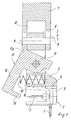
- the press-fit tool for pressing in electrical connection components in printed circuit boards for example of pin headers 1 with 90 ° angled pins 2 is formed in several parts and includes a pressure part 3, the underside has a pressure surface 4, which can be placed on top of the insulating 5 of the pin header 1.
- a lifting part 7 slidably guided, which has a movement play a in relation to the printing part 3.
- a double-projecting pin 8 is arranged for this purpose in the upper end 6 of the pressure member 3, which is guided in elongated vertical guide slots 9 in the lifting part 7. If, for example, in the open position of the tool shown in Figure 1, the bolt 8 is located at one end of the guide slots 9, defines the distance of the free bolt surface to the other end of the guide slots 9, the movement play a.
- a downwardly open receiving space 10 is further formed, in which the upper end 6 of the pressure member 3 during the movement of the lifting member 7 may occur on the pressure member.
- a support member 12 is further rotatably supported with two mutually spaced brackets 12a on an axis 13. Die Ausnaturalung 11 des Druckmaschines 3 ist mit dem Abconnectedeil 12sky.
- the Support member 12 has at the lower end of a downwardly projecting leg 14, a support member 15.
- the support member 12 is now arranged with a bracket 12a in the path of the pressure member 3, that during the movement of the lifting member 7 on the pressure member 3 in the phase of overcoming the movement play a from the open position shown in Figure 1 in the in FIG 2 shown closed position, in which latter the supporting element 15 engages under the housing 5 of the pin header 1 ends of the 90 ° pins 2 supporting.
- the movement and the arrangement are designed so that it is ensured that the support is completed before the lifting part 7, the pressure part 3 is ensured in the sense of the transmission of Einpreß kit on the printing part 3. Then then transmits the pressure member 3 by means of the pressure surface 4, the insertion forces on the pin header and their pins.
- the arrangement is such that in the open position shown in Figure 1, the support member 12 is pivoted so that the upper end of the bracket 12a is located directly in the path of the lifting member 7.
- a spring 17 is disposed in the illustrated embodiment in a recess 16 in the pressure part 3, the other end is on the inside of the Leg 14 of the support member 3 is supported and whose spring force is directed to keep the support member 12 in the pivoted open position. The force of the spring 17 is overcome by the lifting part 1 in its downward movement and the associated pivoting of the support member 12.
- Such a press tool is used everywhere there with the advantages mentioned, where electrical connection components are to be pressed, in which the Einpreß technique can not be centrally transmitted to the press-fit.
- the support member in adaptation to such Einpreßbaumaschine then be provided with differently shaped or differently arranged support elements.
Landscapes
- Engineering & Computer Science (AREA)
- Manufacturing & Machinery (AREA)
- Microelectronics & Electronic Packaging (AREA)
- Coupling Device And Connection With Printed Circuit (AREA)
- Combinations Of Printed Boards (AREA)
- Adhesives Or Adhesive Processes (AREA)
- Manufacturing Of Electrical Connectors (AREA)
Description
- Die Erfindung betrifft ein Einpreßwerkzeug zum Einpressen von elektrischen Anschlußbauteilen in Leiterplatten. Bislang sind einteilige Einpreßwerkzeuge handelsüblich, die mit dem Hubmechanismus einer kleinen Presse oder einer sonstigen Hubeinrichtung zu verbinden sind und die dann beim Einpressen auf die nach oben weisende Gehäusefläche der Anschlußbauteile gepreßt werden, um die Einpreßkräfte zu übertragen. Diese Vorgehensweise ist für verschiedene elektrische Anschlußbauteile problematisch, insbesondere bei Stiftleisten, deren einzupressende Stifte um 90° abgewinkelt liegen. In einem solchen Fall können sich die Einpreßkräfte besonders ungünstig auf die Bauteile auswirken. Einpreßkräfte können zu Bauteilverformungen führen. Um dem abzuhelfen, werden gesonderte Einlegeteile genommen und zu Abstützungszwecken der kritischen Stellen in die Anschlußbauteile eingesetzt, die dann nach der Montage für den Einpreßvorgang auch wieder demontiert werden müssen. Der gleichen Problematik unterliegen alle elektrischen Anschlußbauteile, bei denen die Einpreßkräfte nicht zentrisch auf den einzupressenden Stift übertragen werden können.
- Ein mehrteiliges Einpresswerkzeug ist aus DE 86 22 117.3 bekannt.
- Der vorliegenden Erfindung liegt von daher die Aufgabe zugrunde, ein Einpreßwerkzeug zu schaffen, das den umständlichen Einsatz von gesonderten Einlegeteilen auch bei den genannten problembehafteten elektrischen Anschlußbauteilen vermeidet und dabei eine Gefahr der Verformung der Anschlußbauteile vermieden wird.
- Die erfindungsgemäße Lösung ergibt sich aus dem kennzeichnenden Teil des Anspruches 1. Die Mehrteiligkeit des Einpreßwerkzeuges mit einem auf das Gehäuse des Anschlußbauteiles aufsetzbaren Druckteil, einem ein Bewegungsspiel gegenüber dem Druckteil aufweisenden Hubteil und einem von dem Hubteil zu betätigenden drehbaren Abstützteil mit Abstützelementen ermöglicht es, mittels des verschiebbaren Hubteiles zunächst das drehbare Abstützteil mit den Abstützelementen in das Anschlußbauteil einzuschwenken und damit alle kritischen Zonen abzustützen, bevor das Hubteil das Druckteil erreicht und mit Hilfe des Druckteiles die Einpreßkräfte auf das Gehäuse des Anschlußbauteiles aufbringt. Damit ist gewährleistet, daß zwangsläufig bei jedem Einpreßvorgang eine sichere Abstützung der kritischen Stellen der problembehafteten Anschlußbauteile erfolgt, bevor die Einpreßkräfte aufgebracht werden. Ein derartiges Einpreßwerkzeug stellt dabei sicher, daß sich das Einpressen von problematischen elektrischen Anschlußbauteilen automatisieren läßt, ohne daß die Gefahr von Verformungen der Bauteile besteht.
- Zu Beginn der Abhebebewegung des Einpreßwerkzeuges ist das drehbare Abstützteil mit den Abstützelementen aus dem eingepreßten Anschlußbauteil herauszuschwenken. Dies kann in Art einer kraftschlüssigen Bewegungskopplung in denkbar einfacher Weise beispielsweise dadurch geschehen, daß zwischen dem Druckteil und dem daran gelagerten Abstützteil eine Feder angeordnet ist, deren Federkraft auf die Herausschwenkung des Anschlußteiles gerichtet ist. Die Kraft der Feder wird dabei bei der Einschwenkung des Abstützteiles durch das Hubteil überwunden. Weitere bevorzugte Ausgestaltungen, die insbesondere auch den einfachen konstruktiven Aufbau eines derartigen Einpreßwerkzeuges betreffen, sind in Unteransprüchen gekennzeichnet.
- Ein bevorzugtes Ausführungsbeispiel eines erfindungsgemäßen Einpreßwerkzeuges wird nachstehend unter Bezugnahme auf die beigefügte Zeichnung näher beschrieben.
- Es zeigen:
- Figur 1
- ein Einpreßwerkzeug gemäß der Erfindung im Querschnitt in der Offenstellung,
- Figur 2
- das Einpreßwerkzeug nach Figur 1 in der Schließstellung,
- Figur 3
- eine perspektivische, gebrochene Seitenansicht des Einpreßwerkzeuges.
- Das Einpreßwerkzeug zum Einpressen elektrischer Anschlußbauteile in Leiterplatten, beispielsweise von Stiftleisten 1 mit um 90° abgewinkelten Stiften 2 ist mehrteilig ausgebildet und beinhaltet ein Druckteil 3, das unterseitig eine Druckfläche 4 hat, die oberseitig auf das Isolierstoffgehäuse 5 der Stiftleiste 1 aufgesetzt werden kann.
- Auf dem oberen, im wesentlichen im Querschnitt rechteckig ausgebildeten Ende 6 des Druckteiles 3 ist heb- und senkbar ein Hubteil 7 verschieblich geführt, das ein Bewegungsspiel a im Verhältnis zum Druckteil 3 aufweist. Im dargestellten Ausführungsbeispiel ist hierzu in dem oberen Ende 6 des Druckteiles 3 ein beidseitig vorstehender Bolzen 8 angeordnet, der in länglichen senkrechten Führungsschlitzen 9 im Hubteil 7 geführt ist. Wenn, beispielsweise in der in Figur 1 gezeigten Offenstellung des Werkzeuges, der Bolzen 8 an einem Ende der Führungsschlitze 9 liegt, definiert der Abstand der freien Bolzenoberfläche zum anderen Ende der Führungsschlitze 9 das Bewegungsspiel a. In dem Hubteil 7 ist ferner ein nach unten offener Aufnahmeraum 10 gebildet, in den das obere Ende 6 des Druckteiles 3 bei der Bewegung des Hubteiles 7 auf das Druckteil zu eintreten kann.
- In Aussparungen 11 des Druckteiles 3 ist ferner ein Abstützteil 12 mit zwei voneinander abständigen Bügeln 12a auf einer Achse 13 drehbar gelagert. Das Abstützteil 12 weist am unteren Ende eines nach unten vorstehenden Schenkels 14 ein Abstützelement 15 auf. Das Abstützteil 12 ist nun mit einem Bügel 12a so in der Wegbahn des Druckteiles 3 angeordnet, daß es bei der Bewegung des Hubteiles 7 auf das Druckteil 3 zu in der Phase der Überwindung des Bewegungsspieles a aus der in Figur 1 gezeigten Offenstellung in die in Figur 2 gezeigte Schließstellung verschwenkt wird, in welch letzterer das Abstützelement 15 die im Gehäuse 5 der Stiftleiste 1 befindlichen Enden der 90°-Stifte 2 abstützend untergreift. Das Bewegungsspiel und die Anordnung sind dabei so ausgelegt, daß gewährleistet ist, daß die Abstützung vollzogen ist, bevor das Hubteil 7 das Druckteil 3 im Sinne der Übertragung der Einpreßkräfte auf das Druckteil 3 gewährleistet ist. Danach überträgt dann das Druckteil 3 mittels der Druckfläche 4 die Einpreßkräfte auf die Stiftleiste und deren Stifte.
- Im dargestellten Ausführungsbeispiel ist die Anordnung so getroffen, daß in der in Figur 1 gezeigten Offenstellung das Abstützteil 12 so verschwenkt liegt, daß das eine obere Ende der Bügel 12a unmittelbar in der Wegbahn des Hubteiles 7 liegt.
- Im Sinne einer Bewegungskopplung dergestalt, daß beim Wiederhochfahren des Hubteiles 7 das Abstützteil 12 mit dem Abstützelement 15 wieder aus der Stiftleiste 1 herausschwenkt, ist im dargestellten Ausführungsbeispiel in einer Ausnehmung 16 im Druckteil 3 eine Feder 17 angeordnet, deren anderes Ende sich an der Innenseite des Schenkels 14 des Abstützteiles 3 abstützt und deren Federkraft darauf gerichtet ist, das Abstützteil 12 in der ausgeschwenkten Offenstellung zu halten. Die Kraft der Feder 17 wird vom Hubteil 1 bei seiner Abwärtsbewegung und der damit verbundenen Einschwenkung des Abstützteiles 12 überwunden.
- Ein derartiges Einpreßwerkzeug wird überall dort mit den genannten Vorteilen eingesetzt, wo elektrische Anschlußbauteile einzupressen sind, bei denen die Einpreßkräfte nicht zentrisch auf den Einpreßstift übertragen werden können. Gegebenenfalls ist in Anpassung an derartige Einpreßbauteile dann das Abstützteil mit anders geformten oder anders angeordneten Abstützelementen zu versehen.
- Es ist ferner in Abwandlung der vorstehend beschriebenen Ausführungsformen auch grundsätzlich möglich, eine andere Art der Bewegungskopplung zwischen dem Abstützteil und dem Hubteil zu verwirklichen, etwa dergestalt, daß über bewegungskoppelnde Schwenkflächen oder dergleichen das Abstützteil während der Abwärtsbewegung des Hubteiles in einer linearen Einschubbewegung in das elektrische Anschlußbauteil eingefahren wird.
Claims (8)
- Einpreßwerkzeug, zum Einpressen von elektrischen Anschlußbauteilen in Leiterplatten, wobei das Einpreßwerkzeug mehrteilig ausgebildet ist dadurch gekennzeichnet, daß es ein auf das Gehäuse (5) des Anschlußbauteiles (1) aufsetzbares Druckteil (3) sowie ein Hubteil (7) aufweist, das ein Bewegungsspiel (a) zum Druckteil (3) bis zu dessen Druckbeaufschlagung hat und ferner ein verlagerbares Abstützteil (12, 12a) vorgesehen ist, das so in der Wegbahn des Hubteiles (7) angeordnet ist, daß es nach Überwindung des Bewegungsspieles des Hubteiles (7) zum Druckteil (3) von diesem in das Anschlußbauteil (1) mit Abstützelementen (15) hineinbewegt ist.
- Einpreßwerkzeug nach Anspruch 1, dadurch gekennzeichnet, daß für die Rückführung des Abstützteiles (12, 12a) in die Offenstellung eine das Abstützteil (12, 12a) beaufschlagende Feder (17) vorgesehen ist.
- Einpreßwerkzeug nach Anspruch 1. dadurch gekennzeichnet, daß das Abstützteil (12, 12a) drehbar in dem Druckteil (3) gelagert ist.
- Einpreßwerkzeug nach Anspruch 1, dadurch gekennzeichnet, daß das Hubteil (7) auf dem oberen Ende (6) des Druckteiles (3) verschieblich geführt ist und das Abstützteil (12, 12a) in einer Aussparung (11) des Druckteiles (3) unterhalb des Hubteiles (7) gelagert ist.
- Einpreßwerkzeug nach den Ansprüchen 2 und 4, dadurch gekennzeichnet, daß das Abstützteil (12, 12a) durch die Feder (17) so in die Offenstellung gedrückt ist, daß ein oberes Ende des Abstützteiles (12, 12a) unmittelbar in der Wegbahn des Hubteiles (7) liegt.
- Einpreßwerkzeug nach Anspruch 1 und 4, dadurch gekennzeichnet, daß das Hubteil (7) auf dem oberen Ende (6) des Druckteiles (3) dieses übergreifend angeordnet ist und in dem Druckteil (3) beidseitig aus diesem vorstehende Bolzen (8) angeordnet sind, die in Führungsschlitze (9) im übergreifenden Bereich des Hubteiles (7) eingreifen, wobei der Abstand zwischen dem freien Bereich der Bolzen (8) in der Offenstellungsendlage der Teile zum gegenüberliegenden anderen Ende der Führungsschlitze (9) das Bewegungsspiel (a) definiert.
- Einpreßwerkzeug nach Anspruch 1, dadurch gekennzeichnet, daß das Abstützteil (12, 12a) an einem nach unten weisenden Schenkel (14) ein oder mehrere Abstützelemente (15) auf der dem elektrischen Anschlußbauteil (1) zugewandten Seite aufweist.
- Einpreßwerkzeug nach Anspruch 2, dadurch gekennzeichnet, daß die Feder (17) in einer Ausnehmung (16) des Druckteiles (3) angeordnet ist und sich mit ihrem anderen Ende auf einer zugewandten Fläche des Abstützteiles (12, 12a) abstützt.
Applications Claiming Priority (2)
| Application Number | Priority Date | Filing Date | Title |
|---|---|---|---|
| DE29714747U DE29714747U1 (de) | 1997-08-18 | 1997-08-18 | Einpreßwerkzeug zum Einpressen elektrischer Anschlußbauteile in Leiterplatten |
| DE29714747U | 1997-08-18 |
Publications (3)
| Publication Number | Publication Date |
|---|---|
| EP0898343A2 EP0898343A2 (de) | 1999-02-24 |
| EP0898343A3 EP0898343A3 (de) | 2000-01-12 |
| EP0898343B1 true EP0898343B1 (de) | 2006-04-05 |
Family
ID=8044731
Family Applications (1)
| Application Number | Title | Priority Date | Filing Date |
|---|---|---|---|
| EP19980112955 Expired - Lifetime EP0898343B1 (de) | 1997-08-18 | 1998-07-13 | Einpresswerkzeug zum Einpressen elektrischer Anschlussbauteile in Leiterplatten |
Country Status (2)
| Country | Link |
|---|---|
| EP (1) | EP0898343B1 (de) |
| DE (2) | DE29714747U1 (de) |
Families Citing this family (2)
| Publication number | Priority date | Publication date | Assignee | Title |
|---|---|---|---|---|
| DE102005043033B3 (de) * | 2005-09-09 | 2007-04-12 | Siemens Ag | Pressfit-System zur elektrischen Kontaktierung sowie Verfahren zur Montage des Pressfit-Systems |
| DE202008012657U1 (de) | 2008-09-23 | 2010-02-25 | Usk Karl Utz Sondermaschinen Gmbh | Werkzeug zur Herstellung einer Kontaktierung eines elektronischen Bauelementes mit einer Leiterplatte |
Family Cites Families (10)
| Publication number | Priority date | Publication date | Assignee | Title |
|---|---|---|---|---|
| US4328613A (en) * | 1980-03-27 | 1982-05-11 | Bell Telephone Laboratories, Incorporated | Connector lead insertion method |
| US4543713A (en) * | 1983-08-08 | 1985-10-01 | At&T Technologies, Inc. | Technique for inserting connector leads into a circuit board |
| US4670978A (en) * | 1985-01-28 | 1987-06-09 | Amp Incorporated | Connector mounting press |
| DE8622117U1 (de) * | 1986-08-18 | 1987-08-27 | Guglhör, Magdalena, 8959 Buching | Einpreßwerkzeug zum Einpressen von Kontaktstiften in Leiterplatten |
| US4807357A (en) * | 1987-04-29 | 1989-02-28 | Autosplice, Inc. | Method and apparatus for bending and inserting pin in one sequential operation |
| US4793816A (en) * | 1987-07-20 | 1988-12-27 | Industrial Electronic Hardware | Terminal protector for circuit board connector |
| JP3201047B2 (ja) * | 1993-01-28 | 2001-08-20 | 安藤電気株式会社 | プリント基板へのプレスフィットコネクタ圧入装置 |
| US5499443A (en) * | 1993-10-25 | 1996-03-19 | Ando Electric Co., Ltd. | Connector press-fitting apparatus |
| US5740607A (en) * | 1994-06-30 | 1998-04-21 | Siemens Aktiengesellschaft | Method for equipping a wiring backplane |
| DE19514686A1 (de) * | 1995-04-20 | 1996-10-24 | Samsung Electronics Co Ltd | Zentrierapparat für eine Vorrichtung zum Anbringen von Bausteinen |
-
1997
- 1997-08-18 DE DE29714747U patent/DE29714747U1/de not_active Expired - Lifetime
-
1998
- 1998-07-13 EP EP19980112955 patent/EP0898343B1/de not_active Expired - Lifetime
- 1998-07-13 DE DE59813474T patent/DE59813474D1/de not_active Expired - Fee Related
Also Published As
| Publication number | Publication date |
|---|---|
| EP0898343A3 (de) | 2000-01-12 |
| DE29714747U1 (de) | 1997-10-16 |
| EP0898343A2 (de) | 1999-02-24 |
| DE59813474D1 (de) | 2006-05-18 |
Similar Documents
| Publication | Publication Date | Title |
|---|---|---|
| EP1777720B1 (de) | Elektrisches Bauteil, insbesondere Relaisfassung, mit Federklemmen und Verfahren zu seiner Herstellung | |
| DE4326091C2 (de) | Elektrische Steckvorrichtung und Verfahren zur Montage derselben | |
| DE102008030357B4 (de) | Zwischenverbindungsstruktur für Platinen und Anschlussteile | |
| DE19920981C2 (de) | Elektrischer Verbinder | |
| DE19607548C2 (de) | Abgewinkelter Einpreß-Steckverbinder zum Einpressen in Bohrungen einer Leiterplatte | |
| DE19753076C1 (de) | Elektrische Anschlußklemme, insbesondere Anreihklemme | |
| DE68918487T2 (de) | Elektrische Einrichtung mit verbesserten Leitern für die Oberflächenmontage von gedruckten Schaltungen. | |
| DE19524123C1 (de) | Tragschiene und Stecker zur Kopplung mit einer Tragschiene | |
| DE9217310U1 (de) | Elektrische Verbindung mit Mitteln zum Festlegen von Kontakten | |
| DE8816798U1 (de) | Stiftförmiges Kontaktelement zur Befestigung in Leiterplattenbohrungen | |
| DE19917308B4 (de) | Elektronische Verbinder mit einem Federkontakt | |
| WO2011072643A1 (de) | Kontaktvorrichtung zum befestigen an einer leiterplatte, verfahren zum befestigen einer kontaktvorrichtung an einer leiterplatte und leiterplatte | |
| EP2018684B1 (de) | Modul mit anschlüssen für aktoren und/oder sensoren | |
| DE69409662T2 (de) | Elektrischer verbinder zur oberflächenmontage auf einer leiterplatte | |
| DE2835316C2 (de) | ||
| DE19725966C1 (de) | Steckverbinder für Kartenrandmontage | |
| EP0654170B1 (de) | Thermosicherung und verfahren zu ihrer aktivierung | |
| EP1167670B1 (de) | Befestigungsplatte zur Befestigung eines Scharnierarmes eines Möbelscharniers | |
| DE69902813T2 (de) | Bauweise für den automatisierten anschluss von zwei elektronischen stromkreisen eines kraftfahrzeugs | |
| EP3698440B1 (de) | Befestigungsklemme | |
| DE102024134940A1 (de) | Federkraftklemmanschluss und Leiteranschlussklemme | |
| DE3118057C2 (de) | Anschlußklemme für elektrische Leiter | |
| EP3766130B1 (de) | Kontaktelement mit einem kontaktkörper und einem daran angeordneten federelement | |
| DE10013116B4 (de) | Vorrichtung zur lagerichtigen Befestigung einer Leiterplatte | |
| EP0898343A2 (de) | Einpresswerkzeug zum Einpressen elektrischer Anschlussbauteile in Leiterplatten |
Legal Events
| Date | Code | Title | Description |
|---|---|---|---|
| PUAI | Public reference made under article 153(3) epc to a published international application that has entered the european phase |
Free format text: ORIGINAL CODE: 0009012 |
|
| AK | Designated contracting states |
Kind code of ref document: A2 Designated state(s): DE FR GB IT |
|
| AX | Request for extension of the european patent |
Free format text: AL;LT;LV;MK;RO;SI |
|
| PUAL | Search report despatched |
Free format text: ORIGINAL CODE: 0009013 |
|
| AK | Designated contracting states |
Kind code of ref document: A3 Designated state(s): AT BE CH CY DE DK ES FI FR GB GR IE IT LI LU MC NL PT SE |
|
| AX | Request for extension of the european patent |
Free format text: AL;LT;LV;MK;RO;SI |
|
| RIC1 | Information provided on ipc code assigned before grant |
Free format text: 7H 01R 43/20 A, 7H 05K 13/04 B |
|
| 17P | Request for examination filed |
Effective date: 20000107 |
|
| AKX | Designation fees paid |
Free format text: DE FR GB IT |
|
| GRAP | Despatch of communication of intention to grant a patent |
Free format text: ORIGINAL CODE: EPIDOSNIGR1 |
|
| GRAS | Grant fee paid |
Free format text: ORIGINAL CODE: EPIDOSNIGR3 |
|
| GRAA | (expected) grant |
Free format text: ORIGINAL CODE: 0009210 |
|
| AK | Designated contracting states |
Kind code of ref document: B1 Designated state(s): DE FR GB IT |
|
| REG | Reference to a national code |
Ref country code: GB Ref legal event code: FG4D Free format text: NOT ENGLISH |
|
| REF | Corresponds to: |
Ref document number: 59813474 Country of ref document: DE Date of ref document: 20060518 Kind code of ref document: P |
|
| GBT | Gb: translation of ep patent filed (gb section 77(6)(a)/1977) |
Effective date: 20060612 |
|
| ET | Fr: translation filed | ||
| PLBE | No opposition filed within time limit |
Free format text: ORIGINAL CODE: 0009261 |
|
| STAA | Information on the status of an ep patent application or granted ep patent |
Free format text: STATUS: NO OPPOSITION FILED WITHIN TIME LIMIT |
|
| 26N | No opposition filed |
Effective date: 20070108 |
|
| PGFP | Annual fee paid to national office [announced via postgrant information from national office to epo] |
Ref country code: DE Payment date: 20070719 Year of fee payment: 10 |
|
| PGFP | Annual fee paid to national office [announced via postgrant information from national office to epo] |
Ref country code: GB Payment date: 20070720 Year of fee payment: 10 |
|
| PGFP | Annual fee paid to national office [announced via postgrant information from national office to epo] |
Ref country code: IT Payment date: 20070723 Year of fee payment: 10 |
|
| PGFP | Annual fee paid to national office [announced via postgrant information from national office to epo] |
Ref country code: FR Payment date: 20070710 Year of fee payment: 10 |
|
| GBPC | Gb: european patent ceased through non-payment of renewal fee |
Effective date: 20080713 |
|
| PG25 | Lapsed in a contracting state [announced via postgrant information from national office to epo] |
Ref country code: DE Free format text: LAPSE BECAUSE OF NON-PAYMENT OF DUE FEES Effective date: 20090203 |
|
| REG | Reference to a national code |
Ref country code: FR Ref legal event code: ST Effective date: 20090331 |
|
| PG25 | Lapsed in a contracting state [announced via postgrant information from national office to epo] |
Ref country code: GB Free format text: LAPSE BECAUSE OF NON-PAYMENT OF DUE FEES Effective date: 20080713 |
|
| PG25 | Lapsed in a contracting state [announced via postgrant information from national office to epo] |
Ref country code: IT Free format text: LAPSE BECAUSE OF NON-PAYMENT OF DUE FEES Effective date: 20080713 Ref country code: FR Free format text: LAPSE BECAUSE OF NON-PAYMENT OF DUE FEES Effective date: 20080731 |