EP0897829B1 - Voreinstellungseinrichtung zur Einstellung eines Kfz-Scheinwerfers - Google Patents
Voreinstellungseinrichtung zur Einstellung eines Kfz-Scheinwerfers Download PDFInfo
- Publication number
- EP0897829B1 EP0897829B1 EP19980115545 EP98115545A EP0897829B1 EP 0897829 B1 EP0897829 B1 EP 0897829B1 EP 19980115545 EP19980115545 EP 19980115545 EP 98115545 A EP98115545 A EP 98115545A EP 0897829 B1 EP0897829 B1 EP 0897829B1
- Authority
- EP
- European Patent Office
- Prior art keywords
- adjuster
- seating
- envelope
- seat
- stop
- Prior art date
- Legal status (The legal status is an assumption and is not a legal conclusion. Google has not performed a legal analysis and makes no representation as to the accuracy of the status listed.)
- Expired - Lifetime
Links
- 230000007246 mechanism Effects 0.000 claims description 7
- 239000012530 fluid Substances 0.000 claims description 4
- 238000006073 displacement reaction Methods 0.000 claims description 3
- 229920001971 elastomer Polymers 0.000 claims description 3
- 230000000750 progressive effect Effects 0.000 claims description 3
- 239000000806 elastomer Substances 0.000 claims description 2
- 239000000463 material Substances 0.000 claims description 2
- 238000007789 sealing Methods 0.000 claims 2
- 230000003213 activating effect Effects 0.000 claims 1
- 230000000694 effects Effects 0.000 description 5
- 238000004519 manufacturing process Methods 0.000 description 5
- 238000012986 modification Methods 0.000 description 2
- 230000004048 modification Effects 0.000 description 2
- 230000003068 static effect Effects 0.000 description 2
- 230000006978 adaptation Effects 0.000 description 1
- 230000000712 assembly Effects 0.000 description 1
- 238000000429 assembly Methods 0.000 description 1
- 239000000356 contaminant Substances 0.000 description 1
- 238000003780 insertion Methods 0.000 description 1
- 230000037431 insertion Effects 0.000 description 1
- 238000009434 installation Methods 0.000 description 1
- 238000000034 method Methods 0.000 description 1
- 230000035515 penetration Effects 0.000 description 1
- 238000011084 recovery Methods 0.000 description 1
- XLYOFNOQVPJJNP-UHFFFAOYSA-N water Substances O XLYOFNOQVPJJNP-UHFFFAOYSA-N 0.000 description 1
Images
Classifications
-
- B—PERFORMING OPERATIONS; TRANSPORTING
- B60—VEHICLES IN GENERAL
- B60Q—ARRANGEMENT OF SIGNALLING OR LIGHTING DEVICES, THE MOUNTING OR SUPPORTING THEREOF OR CIRCUITS THEREFOR, FOR VEHICLES IN GENERAL
- B60Q1/00—Arrangement of optical signalling or lighting devices, the mounting or supporting thereof or circuits therefor
- B60Q1/02—Arrangement of optical signalling or lighting devices, the mounting or supporting thereof or circuits therefor the devices being primarily intended to illuminate the way ahead or to illuminate other areas of way or environments
- B60Q1/04—Arrangement of optical signalling or lighting devices, the mounting or supporting thereof or circuits therefor the devices being primarily intended to illuminate the way ahead or to illuminate other areas of way or environments the devices being headlights
- B60Q1/06—Arrangement of optical signalling or lighting devices, the mounting or supporting thereof or circuits therefor the devices being primarily intended to illuminate the way ahead or to illuminate other areas of way or environments the devices being headlights adjustable, e.g. remotely-controlled from inside vehicle
- B60Q1/068—Arrangement of optical signalling or lighting devices, the mounting or supporting thereof or circuits therefor the devices being primarily intended to illuminate the way ahead or to illuminate other areas of way or environments the devices being headlights adjustable, e.g. remotely-controlled from inside vehicle by mechanical means
- B60Q1/0683—Adjustable by rotation of a screw
Definitions
- the present invention relates to an assembly comprising a seating adjuster and a presetting arrangement for the seating adjuster on a vehicle headlight.
- Vehicle headlight seating adjuster assemblies according the preamble of claim 1 are known in the prior art in which a sliding component, actuated manually or by means of a small electric motor, is connected to a corresponding portion of the headlight reflector: the movement of the sliding component determines the sloping of the reflector and a consequent variation in its orientation, so that it is thus possible to adapt the projector light beam to the various load conditions of the vehicle.
- the better known seating adjusters are of the "dynamic” or “step by step” types, in which the projector orientation adjustment is continuous or micrometric.
- the dynamic seating adjusters at present available on the market do not have a static presetting arrangement, which does not call that is to say for the intervention of setting mechanisms for the actual seating adjuster.
- the seating adjuster being required to allow the compensation of such clearances, must be designed in such a way that its sliding component has an extended stroke which in use, proves of no use to cover the seating variations normally called for.
- this requirement has a negative effect upon dimensions, the complexity and the costs of production of the arrangement.
- the purpose of the present invention is to achieve a presetting arrangement for a vehicle headlight seating adjuster which is free from the aforementioned inconveniences and which in particular will allow static compensation of the clearances deriving from the assembly of projector components and those of the bodywork manufacture, operating separately from the control mechanisms of the seating adjuster.
- the said purpose is achieved by the present invention, in that it relates to an assembly comprising a vehicle headlight seating adjuster and a presetting arrangement for the said seating adjuster as claimed in claim 1.
- the arrangement according to the present invention allows the presetting of a seating adjustment for headlights of the dynamic type and of the relative projector, in order to recover the clearances deriving from the assembly of various components of the projector itself and those of the bodywork.
- the support component is effectively secured in a known manner, to the vehicle bodywork: the actuator means and the relative control means of the arrangement according to the invention allow integral displacement of the seating adjuster in relation to the support component, in such a way as to carry the sliding component of the adjuster so as to cooperate with the headlight reflector, thus obtaining the presetting thereof and cancelling the existing clearances, without necessitating the intervention of the actual seating adjuster control mechanisms.
- the arrangement according to the invention also proves of simple and economical design and can be effectively applied to whatsoever dynamic seating adjuster of the conventional type without requiring complex modifications and adaptations thereof, in that it maintains unchanged the structure, the electronic components and the procedure for securing it to the projector body.
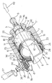
- the figure shows in its arrangement according to reference 1 a presetting arrangement for a vehicle headlight seating adjuster 2, as known and not illustrated for the purpose of simplicity.
- the seating adjuster 2 is of any known type, for instance electrically actuated, and comprises a main body 3 essentially cylindrical and housing the control mechanisms and from a first axial end 4 of which projects a longitudinal screw 5, coaxial with the main body 3 and axially sliding in relation to the latter when the said control mechanisms of the seating adjuster 2 are actuated; the screw 5 has a ball head 6, able to cooperate with a suitable matching component on the headlight reflector, as already known and not illustrated, for the purpose of modifying the orientation thereof.
- a lateral external surface 7 of the main body 3 is provided as from a second end 8 of the main body 3 and opposing the end 4 and for a preset axial extension, with a threaded annular portion 9; the main body 3 also has a stop tooth 10 which extends radially in overhang from a non-threaded portion 11 of the lateral surface 7, comprised between the threaded portion 9 and the end 4.
- the arrangement 1 comprises a support component for the seating adjuster 2 as defined, effectively in a non-restrictive manner illustrated in the figure, with an essentially cylindrical envelope 15, coaxial with the main body 3 of the seating adjuster 2, and externally radial in relation to the latter; the envelope 15 internally defines an essentially cylindrical seat 16 within which is located the body 3, as will be described further on in an axially sliding manner.
- the envelope 15 is closed, at its one axial end 17 by a bottom wall 18, which has a passing hole 19, circular and concentric with the envelope itself, and a sleeve 20, which extends axially in overhang from the bottom wall 18, towards the outside of the envelope 15, and defines the hole 19;
- the sleeve 20 has an internal diameter such as to internally house the screw 5, which slides axially therein, and carries keyed to the outside against the wall 18, a flat annular seal 18, for instance made of rubber.
- the envelope 15 is also provided on an internal radial lateral surface 22, with an axial opening 23, able to house the stop tooth 10 of the seating adjuster 2; as will be explained further on, the stop tooth 10 and the threaded portion 9 also form part of the arrangement assembly 1.
- the envelope 15 has on its end 24 opposing its end 17, an internal cylindrical annular stop 25, coaxial with the envelope 15 and of an internal diameter greater than the internal diameter thereof; the difference in diameters between the stop 25 and the remainder of the envelope 15 defines inside the latter an axial shoulder 26 turned towards to the end 17 of the envelope 15.
- the arrangement 1 also comprises a pair of toothed wheels 30, 31 with perpendicular axes, able to engage with each other.
- the toothed wheel 30 In particular is a circular ring, having a toothed side 32 with preset slope and an essentially flat side 33 opposing side 32.
- the toothed ring 30 is internally threaded in such a way as to admit in screw-like manner the threaded portion 9 of the main body 3 and has an external diameter such as to allow its free insertion, with a slight radial clearance, on the inside of the cylindrical stop 25 of the envelope 15; the ring 30 can thus connect in rotary manner with the stop 25 and its flat side 33 cooperates as a stop against the shoulder 26.
- the toothed wheel 31 is instead a pinion, able to engage with the toothed side 32 of the ring 30; the pinion 31 is mounted at one end of a screw 34 inserted in rotary manner in a suitable seat of a support bracket 35 integral with the envelope 15.
- the screw 34 has on the side opposing the pinion 31, a control means 51, in effect an hexagonal head 36 having internally a seat for a screwdriver 37, for instance, of the cruciform type.
- the arrangement 1 comprises fluid-tight means 38, 40, located to protect the inside of the projector body (known and not illustrated), able to prevent the ingress therein of contaminants such as water, humidity, etc.;
- the securing means comprise a securing ring 38 in elastomer material (of an essentially known type), housed within a suitable annular seat 39 recessed in the screw 5 of the seating adjuster 2, quite apart from the flat seal 40 as quoted and bearing against the bottom wall 18.
- the arrangement 1 allows presetting of the dynamic seating adjuster 2 to compensate manufacturing and assembly clearances, without making use of the adjuster setting facility itself.
- the external part of the assembly formed by the seating adjuster 2 and the arrangement 1 is defined by the envelope 15, which is intended to be secured in a known manner, to the projector body; according to the invention therefore, the seating adjuster 2 is not secured integral with the projector body, as it presently occurs, but the support component suitably provided for in the arrangement 1, in effect the envelope 15; as an example the envelope 15 may have integral securing components, or be inserted into suitable seats, suitably recessed in the projector body and, thereby intended to remain fixed in relation to the vehicle bodywork.
- the threaded portion 9 of the seating adjuster 2, the threaded ring 30, the stop tooth 10 and the relevant opening 23 form as an assembly actuator means 50 able to effect the progressive micrometric adjustment of the whole of the seating adjuster 2 within the cylindrical seating 16, when activated by means of control means 51, consisting for instance of pinion 31, the relative screw 34 and the head 36 of the latter.
- the internally threaded toothed ring 30 is brought into rotation, and being inserted freely inside the cylindrical stop 25 of the envelope 15, can rotate on the corresponding threaded portion 9 of the dynamic adjuster 2; the stop tooth 10 of the seating adjuster 2, engaging with the opening 23 recessed inside the envelope 15, will instead prevent the rotation of the dynamic adjuster 2, but does allow axial sliding within the seating 16, in the direction resulting from the rotation imparted to the pinion 31.
- the actuator means 50 are in fact separate and independent from the control means as such of the seating adjuster 2; as the latter, as already known, achieve a sliding stroke of the component 5 in relation to the main body 3 of the seating adjuster 2, the actuator means 50 allow progressive micrometric displacement of the whole of the seating adjuster 2 (main body 3 and sliding component 5, fixed in relation to each other) within the cylindrical seat 16.
Landscapes
- Engineering & Computer Science (AREA)
- Mechanical Engineering (AREA)
- Lighting Device Outwards From Vehicle And Optical Signal (AREA)
Claims (7)
- Baueinheit, die eine Montagesitz-Einstelleinrichtung (2) eines Fahrzeugscheinwerfers und eine Voreinstellanordnung (1) für die Montagesitz-Einstelleinrichtung umfaßt, wobei die Montagesitz-Einstelleinrichtung (2) einen Hauptkörper (3) und eine in bezug auf den Hauptkörper (3) gleitende Komponente (5) umfaßt, wobei die Gleitkomponente (5) in bezug auf den Hauptkörper (3) mittels eines Steuermechanismus beweglich ist, der im Hauptkörper (3) untergebracht ist und mit einer geeigneten Einstellkomponente des Scheinwerfers zusammenwirkt, um dessen Orientierung einzustellen; dadurch gekennzeichnet, daß die Voreinstellanordnung (1) eine Trägerkomponente (15), die einen Sitz (16) für die Montagesitz-Einstelleinrichtung (2) definiert, wobei die Montagesitz-Einstelleinrichtung (2) im Sitz (16) so angebracht ist, daß sie längs einer Symmetrieachse des letzteren gleiten kann, Aktuatormittel (50), die eine progressive mikrometrische Verschiebung der Montagesitz-Einstelleinrichtung (2) innerhalb des Sitzes (16) gewährleisten, sowie Steuermittel (51) zum Aktivieren der Aktuatormittel (50), umfaßt; wobei die Aktuatormittel (50) von den Steuermitteln (51) der Montagesitz-Einstelleinrichtung (2) getrennt sind und unabhängig hiervon arbeiten.
- Baueinheit nach Anspruch 1, dadurch gekennzeichnet, daß die Trägerkomponente eine den Sitz (16) definierende Hülle (15) umfaßt, wobei der Hauptkörper (3) der Montagesitz-Einstelleinrichtung (2) und der Sitz (16) im wesentlichen zylindrisch und koaxial sind und der zylindrische Körper (3) so beschaffen ist, daß er im Sitz (16) axial gleitet; und die Aktuatormittel (50) einen Gewindeabschnitt (9) einer radial äußeren seitlichen Oberfläche (7) des Hauptkörpers (3) der Montagesitz-Einstelleinrichtung (2), einen Kreisring (30) mit Innengewinde, der den Gewindeabschnitt (9), der in ihn geschraubt ist, aufnehmen kann, Axialeinstellmittel (26) für den Gewindering (30) sowie Anschlagmittel (10, 23), die die Drehung des Hauptkörpers (3) der Montagesitz-Einstelleinrichtung (2) in bezug auf den Sitz (16) verhindern können, umfassen.
- Baueinheit nach Anspruch 2, dadurch gekennzeichnet, daß die Hülle (15) ein erstes axiales Ende (24) und einen inneren, zylindrischen, ringförmigen Anschlag (25) besitzt, der zur Hülle (15) koaxial ist und einen Innendurchmesser aufweist, der größer als der Innendurchmesser der Hülle (15) ist; wobei der Gewindering (30) einen Außendurchmesser besitzt, derart, daß er mit einem geringen radialen Spiel in den zylindrischen Anschlag (25) frei eingeführt werden kann; wobei die Axialeinstellmittel eine axiale Schulter (26) umfassen, die mit einem Anschlag mit einer ersten im wesentlichen flachen Seite (33) des Gewinderings (30) zusammenwirken kann, wobei die Schulter (26) in der Hülle (15) näher am ersten Ende (24) der letzteren durch die Durchmesserdifferenz zwischen dem inneren, zylindrischen Anschlag (25) der Hülle (15) und dem Rest der letzteren definiert ist und zu einem zweiten Ende (17) der Hülle (15), das dem ersten Ende (24) gegenüberliegt, gerichtet ist.
- Baueinheit nach Anspruch 3, dadurch gekennzeichnet, daß der Gewindering (30) außerdem gegenüber der ersten flachen Seite (33) mit einer zweiten Gewindeseite (32) versehen ist, die eine im voraus festgelegte Neigung in bezug auf die jene besitzt; die Steuermittel (51) ein Zahnrad (31) aufweisen, das mit der gezahnten Seite (32) des Gewinderings (30) in Eingriff gelangen kann und mit einem Ende der Schraube (34) einteilig verkeilt ist, wobei die Schraube (34) drehbar in einen Trägerarm (35) eingeführt ist, der einteilig mit der Hülle (15) ausgebildet ist und auf der dem Zahnrad (31) gegenüberliegenden Seite Greifmittel (36) besitzt, die die Drehung der Schraube (34) in bezug auf den Arm (35) ermöglichen.
- Baueinheit nach Anspruch 4, dadurch gekennzeichnet, daß die Anschlagmittel wenigstens einen Anschlagzahn (10), der sich von einem gewindefreien Abschnitt (11) der Seitenoberfläche (7) des Hauptkörpers (3) der Montagesitz-Einstelleinrichtung (2) radial überstehend erstreckt; wobei der Anschlagzahn (10) in einem Relativeinstellsitz (23), der in einer radial inneren Seitenoberfläche (22) der Hülle (15) ausgespart ist, in Eingriff ist.
- Baueinheit nach Anspruch 5, dadurch gekennzeichnet, daß die Hülle (15) an ihrem zweiten Ende (17) durch eine Bodenwand (18) verschlossen ist, die ein kreisförmiges Durchgangsloch (19), das zur Hülle (15) konzentrisch ist, sowie eine Hülse (20) umfaßt, die sich von der Bodenwand (18) axial überstehend zur Außenseite der Hülle (15) erstreckt und ein Loch (19) definiert, das innen mit einem radialen Spiel die Gleitkomponente (5) der Montagesitz-Einstelleinrlchtung (2) aufnehmen kann.
- Baueinheit nach Anspruch 6, dadurch gekennzeichnet, daß sie Fluiddichtungsmittel umfaßt; wobei die Fluiddichtungsmittel wenigstens einen Ring (38) aus einem elastomeren Werkstoff, der in einem zugehörigen ringförmigen Sitz (39) untergebracht ist, der in der Gleitkomponente (5) der Montagesitz-Einstelleinrichtung (2) ausgespart ist, sowie eine flache ringförmige Dichtung (40), die wie ein Anschlag an der Bodenwand (18) verkeilt ist, umfassen; wobei der Ring (38) und die Dichtung (40) fluidartig mit der Hülse (20) zusammenwirken können, um ein Eindringen von Fluiden in einen Projektorkörper des Scheinwerfers zu verhindern.
Applications Claiming Priority (2)
| Application Number | Priority Date | Filing Date | Title |
|---|---|---|---|
| IT97TO000755 IT1293983B1 (it) | 1997-08-22 | 1997-08-22 | Dispositivo di preregolazione per un correttore d'assetto di un faro di un veicolo |
| ITTO970755 | 1997-08-22 |
Publications (2)
| Publication Number | Publication Date |
|---|---|
| EP0897829A1 EP0897829A1 (de) | 1999-02-24 |
| EP0897829B1 true EP0897829B1 (de) | 2002-04-10 |
Family
ID=11415962
Family Applications (1)
| Application Number | Title | Priority Date | Filing Date |
|---|---|---|---|
| EP19980115545 Expired - Lifetime EP0897829B1 (de) | 1997-08-22 | 1998-08-18 | Voreinstellungseinrichtung zur Einstellung eines Kfz-Scheinwerfers |
Country Status (4)
| Country | Link |
|---|---|
| EP (1) | EP0897829B1 (de) |
| DE (1) | DE69804730T2 (de) |
| ES (1) | ES2174360T3 (de) |
| IT (1) | IT1293983B1 (de) |
Families Citing this family (1)
| Publication number | Priority date | Publication date | Assignee | Title |
|---|---|---|---|---|
| AT514129B1 (de) * | 2013-04-09 | 2015-06-15 | Zizala Lichtsysteme Gmbh | Fahrzeugscheinwerfer |
Family Cites Families (2)
| Publication number | Priority date | Publication date | Assignee | Title |
|---|---|---|---|---|
| US5497301A (en) * | 1995-02-13 | 1996-03-05 | General Motors Corporation | Headlamp adjustment mechanism |
| CA2185361A1 (en) * | 1995-10-20 | 1997-04-21 | Todd H. Christian | Two-part housing for vehicle headlamp adjusting mechanism |
-
1997
- 1997-08-22 IT IT97TO000755 patent/IT1293983B1/it active IP Right Grant
-
1998
- 1998-08-18 ES ES98115545T patent/ES2174360T3/es not_active Expired - Lifetime
- 1998-08-18 DE DE1998604730 patent/DE69804730T2/de not_active Expired - Fee Related
- 1998-08-18 EP EP19980115545 patent/EP0897829B1/de not_active Expired - Lifetime
Also Published As
| Publication number | Publication date |
|---|---|
| DE69804730D1 (de) | 2002-05-16 |
| EP0897829A1 (de) | 1999-02-24 |
| DE69804730T2 (de) | 2002-10-17 |
| ITTO970755A1 (it) | 1999-02-22 |
| ES2174360T3 (es) | 2002-11-01 |
| IT1293983B1 (it) | 1999-03-15 |
Similar Documents
| Publication | Publication Date | Title |
|---|---|---|
| US6257747B1 (en) | Headlamp adjuster | |
| US6902045B2 (en) | Apparatus, system and method for a vehicle suspension system | |
| US9394738B2 (en) | System for opening and closing a flap | |
| EP1939020B1 (de) | Teleskopischer Stellantrieb | |
| US7066632B2 (en) | Adjuster for headlamp assembly | |
| US20070041206A1 (en) | Motorized lamp adjuster | |
| EP2105327B1 (de) | Teleskopischer Stellantrieb | |
| CN115244316A (zh) | 包括扭矩限制装置的致动驱动器 | |
| GB2109082A (en) | A headlamp for vehicles especially for motor vehicles | |
| US7198392B2 (en) | Torque limiting adjuster | |
| US11002060B2 (en) | Drive unit assembly for a window regulator | |
| US20190270401A1 (en) | Adjusting screw | |
| US6450674B2 (en) | Headlamp adjuster configured to prevent over-travel of an adjuster output shaft | |
| EP0897829B1 (de) | Voreinstellungseinrichtung zur Einstellung eines Kfz-Scheinwerfers | |
| JP2698974B2 (ja) | 自動車の前照灯における反射鏡傾斜角の調節装置 | |
| KR20110115515A (ko) | 차량용 아웃사이드 미러 장치 | |
| US6264010B1 (en) | Disc brake | |
| JPH0214939A (ja) | 自動車用の前照灯 | |
| US20210163059A1 (en) | Steering apparatus | |
| US20020163267A1 (en) | Drive device | |
| US6447154B1 (en) | Headlamp adjuster with overload clutch mechanism | |
| US6796693B2 (en) | 180-degree adjuster | |
| US20040240222A1 (en) | Headlamp adjuster | |
| US11391346B2 (en) | Power steering assembly having a spring retainer for a compensation mechanism | |
| KR101412452B1 (ko) | 축방향 고정부를 가진 트랜스미션 장치 |
Legal Events
| Date | Code | Title | Description |
|---|---|---|---|
| PUAI | Public reference made under article 153(3) epc to a published international application that has entered the european phase |
Free format text: ORIGINAL CODE: 0009012 |
|
| AK | Designated contracting states |
Kind code of ref document: A1 Designated state(s): DE ES FR GB |
|
| AX | Request for extension of the european patent |
Free format text: AL;LT;LV;MK;RO;SI |
|
| 17P | Request for examination filed |
Effective date: 19990226 |
|
| AKX | Designation fees paid |
Free format text: DE ES FR GB |
|
| RAP1 | Party data changed (applicant data changed or rights of an application transferred) |
Owner name: AUTOMOTIVE LIGHTING ITALIA SPA |
|
| 17Q | First examination report despatched |
Effective date: 20001010 |
|
| GRAG | Despatch of communication of intention to grant |
Free format text: ORIGINAL CODE: EPIDOS AGRA |
|
| GRAG | Despatch of communication of intention to grant |
Free format text: ORIGINAL CODE: EPIDOS AGRA |
|
| GRAH | Despatch of communication of intention to grant a patent |
Free format text: ORIGINAL CODE: EPIDOS IGRA |
|
| REG | Reference to a national code |
Ref country code: GB Ref legal event code: IF02 |
|
| GRAH | Despatch of communication of intention to grant a patent |
Free format text: ORIGINAL CODE: EPIDOS IGRA |
|
| GRAA | (expected) grant |
Free format text: ORIGINAL CODE: 0009210 |
|
| AK | Designated contracting states |
Kind code of ref document: B1 Designated state(s): DE ES FR GB |
|
| REF | Corresponds to: |
Ref document number: 69804730 Country of ref document: DE Date of ref document: 20020516 |
|
| ET | Fr: translation filed | ||
| PGFP | Annual fee paid to national office [announced via postgrant information from national office to epo] |
Ref country code: GB Payment date: 20020902 Year of fee payment: 5 |
|
| REG | Reference to a national code |
Ref country code: ES Ref legal event code: FG2A Ref document number: 2174360 Country of ref document: ES Kind code of ref document: T3 |
|
| PLBE | No opposition filed within time limit |
Free format text: ORIGINAL CODE: 0009261 |
|
| STAA | Information on the status of an ep patent application or granted ep patent |
Free format text: STATUS: NO OPPOSITION FILED WITHIN TIME LIMIT |
|
| 26N | No opposition filed |
Effective date: 20030113 |
|
| PG25 | Lapsed in a contracting state [announced via postgrant information from national office to epo] |
Ref country code: GB Free format text: LAPSE BECAUSE OF NON-PAYMENT OF DUE FEES Effective date: 20030818 |
|
| GBPC | Gb: european patent ceased through non-payment of renewal fee |
Effective date: 20030818 |
|
| PGFP | Annual fee paid to national office [announced via postgrant information from national office to epo] |
Ref country code: ES Payment date: 20040805 Year of fee payment: 7 |
|
| PGFP | Annual fee paid to national office [announced via postgrant information from national office to epo] |
Ref country code: DE Payment date: 20041019 Year of fee payment: 7 |
|
| PG25 | Lapsed in a contracting state [announced via postgrant information from national office to epo] |
Ref country code: ES Free format text: LAPSE BECAUSE OF NON-PAYMENT OF DUE FEES Effective date: 20050819 |
|
| PG25 | Lapsed in a contracting state [announced via postgrant information from national office to epo] |
Ref country code: DE Free format text: LAPSE BECAUSE OF NON-PAYMENT OF DUE FEES Effective date: 20060301 |
|
| REG | Reference to a national code |
Ref country code: ES Ref legal event code: FD2A Effective date: 20050819 |
|
| REG | Reference to a national code |
Ref country code: FR Ref legal event code: PLFP Year of fee payment: 19 |
|
| REG | Reference to a national code |
Ref country code: FR Ref legal event code: PLFP Year of fee payment: 20 |
|
| PGFP | Annual fee paid to national office [announced via postgrant information from national office to epo] |
Ref country code: FR Payment date: 20170720 Year of fee payment: 20 |