EP0897829B1 - Presetting arrangement for a vehicle headlight seating adjuster - Google Patents
Presetting arrangement for a vehicle headlight seating adjuster Download PDFInfo
- Publication number
- EP0897829B1 EP0897829B1 EP19980115545 EP98115545A EP0897829B1 EP 0897829 B1 EP0897829 B1 EP 0897829B1 EP 19980115545 EP19980115545 EP 19980115545 EP 98115545 A EP98115545 A EP 98115545A EP 0897829 B1 EP0897829 B1 EP 0897829B1
- Authority
- EP
- European Patent Office
- Prior art keywords
- adjuster
- seating
- envelope
- seat
- stop
- Prior art date
- Legal status (The legal status is an assumption and is not a legal conclusion. Google has not performed a legal analysis and makes no representation as to the accuracy of the status listed.)
- Expired - Lifetime
Links
Images
Classifications
-
- B—PERFORMING OPERATIONS; TRANSPORTING
- B60—VEHICLES IN GENERAL
- B60Q—ARRANGEMENT OF SIGNALLING OR LIGHTING DEVICES, THE MOUNTING OR SUPPORTING THEREOF OR CIRCUITS THEREFOR, FOR VEHICLES IN GENERAL
- B60Q1/00—Arrangement of optical signalling or lighting devices, the mounting or supporting thereof or circuits therefor
- B60Q1/02—Arrangement of optical signalling or lighting devices, the mounting or supporting thereof or circuits therefor the devices being primarily intended to illuminate the way ahead or to illuminate other areas of way or environments
- B60Q1/04—Arrangement of optical signalling or lighting devices, the mounting or supporting thereof or circuits therefor the devices being primarily intended to illuminate the way ahead or to illuminate other areas of way or environments the devices being headlights
- B60Q1/06—Arrangement of optical signalling or lighting devices, the mounting or supporting thereof or circuits therefor the devices being primarily intended to illuminate the way ahead or to illuminate other areas of way or environments the devices being headlights adjustable, e.g. remotely-controlled from inside vehicle
- B60Q1/068—Arrangement of optical signalling or lighting devices, the mounting or supporting thereof or circuits therefor the devices being primarily intended to illuminate the way ahead or to illuminate other areas of way or environments the devices being headlights adjustable, e.g. remotely-controlled from inside vehicle by mechanical means
- B60Q1/0683—Adjustable by rotation of a screw
Definitions
- the present invention relates to an assembly comprising a seating adjuster and a presetting arrangement for the seating adjuster on a vehicle headlight.
- Vehicle headlight seating adjuster assemblies according the preamble of claim 1 are known in the prior art in which a sliding component, actuated manually or by means of a small electric motor, is connected to a corresponding portion of the headlight reflector: the movement of the sliding component determines the sloping of the reflector and a consequent variation in its orientation, so that it is thus possible to adapt the projector light beam to the various load conditions of the vehicle.
- the better known seating adjusters are of the "dynamic” or “step by step” types, in which the projector orientation adjustment is continuous or micrometric.
- the dynamic seating adjusters at present available on the market do not have a static presetting arrangement, which does not call that is to say for the intervention of setting mechanisms for the actual seating adjuster.
- the seating adjuster being required to allow the compensation of such clearances, must be designed in such a way that its sliding component has an extended stroke which in use, proves of no use to cover the seating variations normally called for.
- this requirement has a negative effect upon dimensions, the complexity and the costs of production of the arrangement.
- the purpose of the present invention is to achieve a presetting arrangement for a vehicle headlight seating adjuster which is free from the aforementioned inconveniences and which in particular will allow static compensation of the clearances deriving from the assembly of projector components and those of the bodywork manufacture, operating separately from the control mechanisms of the seating adjuster.
- the said purpose is achieved by the present invention, in that it relates to an assembly comprising a vehicle headlight seating adjuster and a presetting arrangement for the said seating adjuster as claimed in claim 1.
- the arrangement according to the present invention allows the presetting of a seating adjustment for headlights of the dynamic type and of the relative projector, in order to recover the clearances deriving from the assembly of various components of the projector itself and those of the bodywork.
- the support component is effectively secured in a known manner, to the vehicle bodywork: the actuator means and the relative control means of the arrangement according to the invention allow integral displacement of the seating adjuster in relation to the support component, in such a way as to carry the sliding component of the adjuster so as to cooperate with the headlight reflector, thus obtaining the presetting thereof and cancelling the existing clearances, without necessitating the intervention of the actual seating adjuster control mechanisms.
- the arrangement according to the invention also proves of simple and economical design and can be effectively applied to whatsoever dynamic seating adjuster of the conventional type without requiring complex modifications and adaptations thereof, in that it maintains unchanged the structure, the electronic components and the procedure for securing it to the projector body.
- the figure shows in its arrangement according to reference 1 a presetting arrangement for a vehicle headlight seating adjuster 2, as known and not illustrated for the purpose of simplicity.
- the seating adjuster 2 is of any known type, for instance electrically actuated, and comprises a main body 3 essentially cylindrical and housing the control mechanisms and from a first axial end 4 of which projects a longitudinal screw 5, coaxial with the main body 3 and axially sliding in relation to the latter when the said control mechanisms of the seating adjuster 2 are actuated; the screw 5 has a ball head 6, able to cooperate with a suitable matching component on the headlight reflector, as already known and not illustrated, for the purpose of modifying the orientation thereof.
- a lateral external surface 7 of the main body 3 is provided as from a second end 8 of the main body 3 and opposing the end 4 and for a preset axial extension, with a threaded annular portion 9; the main body 3 also has a stop tooth 10 which extends radially in overhang from a non-threaded portion 11 of the lateral surface 7, comprised between the threaded portion 9 and the end 4.
- the arrangement 1 comprises a support component for the seating adjuster 2 as defined, effectively in a non-restrictive manner illustrated in the figure, with an essentially cylindrical envelope 15, coaxial with the main body 3 of the seating adjuster 2, and externally radial in relation to the latter; the envelope 15 internally defines an essentially cylindrical seat 16 within which is located the body 3, as will be described further on in an axially sliding manner.
- the envelope 15 is closed, at its one axial end 17 by a bottom wall 18, which has a passing hole 19, circular and concentric with the envelope itself, and a sleeve 20, which extends axially in overhang from the bottom wall 18, towards the outside of the envelope 15, and defines the hole 19;
- the sleeve 20 has an internal diameter such as to internally house the screw 5, which slides axially therein, and carries keyed to the outside against the wall 18, a flat annular seal 18, for instance made of rubber.
- the envelope 15 is also provided on an internal radial lateral surface 22, with an axial opening 23, able to house the stop tooth 10 of the seating adjuster 2; as will be explained further on, the stop tooth 10 and the threaded portion 9 also form part of the arrangement assembly 1.
- the envelope 15 has on its end 24 opposing its end 17, an internal cylindrical annular stop 25, coaxial with the envelope 15 and of an internal diameter greater than the internal diameter thereof; the difference in diameters between the stop 25 and the remainder of the envelope 15 defines inside the latter an axial shoulder 26 turned towards to the end 17 of the envelope 15.
- the arrangement 1 also comprises a pair of toothed wheels 30, 31 with perpendicular axes, able to engage with each other.
- the toothed wheel 30 In particular is a circular ring, having a toothed side 32 with preset slope and an essentially flat side 33 opposing side 32.
- the toothed ring 30 is internally threaded in such a way as to admit in screw-like manner the threaded portion 9 of the main body 3 and has an external diameter such as to allow its free insertion, with a slight radial clearance, on the inside of the cylindrical stop 25 of the envelope 15; the ring 30 can thus connect in rotary manner with the stop 25 and its flat side 33 cooperates as a stop against the shoulder 26.
- the toothed wheel 31 is instead a pinion, able to engage with the toothed side 32 of the ring 30; the pinion 31 is mounted at one end of a screw 34 inserted in rotary manner in a suitable seat of a support bracket 35 integral with the envelope 15.
- the screw 34 has on the side opposing the pinion 31, a control means 51, in effect an hexagonal head 36 having internally a seat for a screwdriver 37, for instance, of the cruciform type.
- the arrangement 1 comprises fluid-tight means 38, 40, located to protect the inside of the projector body (known and not illustrated), able to prevent the ingress therein of contaminants such as water, humidity, etc.;
- the securing means comprise a securing ring 38 in elastomer material (of an essentially known type), housed within a suitable annular seat 39 recessed in the screw 5 of the seating adjuster 2, quite apart from the flat seal 40 as quoted and bearing against the bottom wall 18.
- the arrangement 1 allows presetting of the dynamic seating adjuster 2 to compensate manufacturing and assembly clearances, without making use of the adjuster setting facility itself.
- the external part of the assembly formed by the seating adjuster 2 and the arrangement 1 is defined by the envelope 15, which is intended to be secured in a known manner, to the projector body; according to the invention therefore, the seating adjuster 2 is not secured integral with the projector body, as it presently occurs, but the support component suitably provided for in the arrangement 1, in effect the envelope 15; as an example the envelope 15 may have integral securing components, or be inserted into suitable seats, suitably recessed in the projector body and, thereby intended to remain fixed in relation to the vehicle bodywork.
- the threaded portion 9 of the seating adjuster 2, the threaded ring 30, the stop tooth 10 and the relevant opening 23 form as an assembly actuator means 50 able to effect the progressive micrometric adjustment of the whole of the seating adjuster 2 within the cylindrical seating 16, when activated by means of control means 51, consisting for instance of pinion 31, the relative screw 34 and the head 36 of the latter.
- the internally threaded toothed ring 30 is brought into rotation, and being inserted freely inside the cylindrical stop 25 of the envelope 15, can rotate on the corresponding threaded portion 9 of the dynamic adjuster 2; the stop tooth 10 of the seating adjuster 2, engaging with the opening 23 recessed inside the envelope 15, will instead prevent the rotation of the dynamic adjuster 2, but does allow axial sliding within the seating 16, in the direction resulting from the rotation imparted to the pinion 31.
- the actuator means 50 are in fact separate and independent from the control means as such of the seating adjuster 2; as the latter, as already known, achieve a sliding stroke of the component 5 in relation to the main body 3 of the seating adjuster 2, the actuator means 50 allow progressive micrometric displacement of the whole of the seating adjuster 2 (main body 3 and sliding component 5, fixed in relation to each other) within the cylindrical seat 16.
Description
- The present invention relates to an assembly comprising a seating adjuster and a presetting arrangement for the seating adjuster on a vehicle headlight.
- Vehicle headlight seating adjuster assemblies according the preamble of claim 1 are known in the prior art in which a sliding component, actuated manually or by means of a small electric motor, is connected to a corresponding portion of the headlight reflector: the movement of the sliding component determines the sloping of the reflector and a consequent variation in its orientation, so that it is thus possible to adapt the projector light beam to the various load conditions of the vehicle. The better known seating adjusters are of the "dynamic" or "step by step" types, in which the projector orientation adjustment is continuous or micrometric.
- It is known that this type of seating adjusters requires an initial presetting at the time of installation of the headlight on the vehicle, necessitated owing to the inevitable presence of manufacturing clearances in the bodywork and clearances deriving from the assembly of the various components of the projector.
- The dynamic seating adjusters at present available on the market do not have a static presetting arrangement, which does not call that is to say for the intervention of setting mechanisms for the actual seating adjuster. In consequence, the seating adjuster, being required to allow the compensation of such clearances, must be designed in such a way that its sliding component has an extended stroke which in use, proves of no use to cover the seating variations normally called for. Clearly this requirement has a negative effect upon dimensions, the complexity and the costs of production of the arrangement.
- The purpose of the present invention is to achieve a presetting arrangement for a vehicle headlight seating adjuster which is free from the aforementioned inconveniences and which in particular will allow static compensation of the clearances deriving from the assembly of projector components and those of the bodywork manufacture, operating separately from the control mechanisms of the seating adjuster.
- The said purpose is achieved by the present invention, in that it relates to an assembly comprising a vehicle headlight seating adjuster and a presetting arrangement for the said seating adjuster as claimed in claim 1.
- In that manner, the arrangement according to the present invention allows the presetting of a seating adjustment for headlights of the dynamic type and of the relative projector, in order to recover the clearances deriving from the assembly of various components of the projector itself and those of the bodywork. The support component is effectively secured in a known manner, to the vehicle bodywork: the actuator means and the relative control means of the arrangement according to the invention allow integral displacement of the seating adjuster in relation to the support component, in such a way as to carry the sliding component of the adjuster so as to cooperate with the headlight reflector, thus obtaining the presetting thereof and cancelling the existing clearances, without necessitating the intervention of the actual seating adjuster control mechanisms. The arrangement according to the invention also proves of simple and economical design and can be effectively applied to whatsoever dynamic seating adjuster of the conventional type without requiring complex modifications and adaptations thereof, in that it maintains unchanged the structure, the electronic components and the procedure for securing it to the projector body.
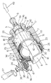
- Other features and advantages of the invention will become clear from the description which follows of a non-restrictive operating example, also referring to the appended figure of the drawing, which is a part section perspective view of a presetting arrangement for a vehicle headlight seating adjuster manufactured according to the invention.
- The figure shows in its arrangement according to reference 1 a presetting arrangement for a vehicle headlight seating adjuster 2, as known and not illustrated for the purpose of simplicity.
- The seating adjuster 2 is of any known type, for instance electrically actuated, and comprises a main body 3 essentially cylindrical and housing the control mechanisms and from a first
axial end 4 of which projects alongitudinal screw 5, coaxial with the main body 3 and axially sliding in relation to the latter when the said control mechanisms of the seating adjuster 2 are actuated; thescrew 5 has a ball head 6, able to cooperate with a suitable matching component on the headlight reflector, as already known and not illustrated, for the purpose of modifying the orientation thereof. - According to the invention, a lateral external surface 7 of the main body 3 is provided as from a
second end 8 of the main body 3 and opposing theend 4 and for a preset axial extension, with a threaded annular portion 9; the main body 3 also has astop tooth 10 which extends radially in overhang from anon-threaded portion 11 of the lateral surface 7, comprised between the threaded portion 9 and theend 4. - The arrangement 1 comprises a support component for the seating adjuster 2 as defined, effectively in a non-restrictive manner illustrated in the figure, with an essentially
cylindrical envelope 15, coaxial with the main body 3 of the seating adjuster 2, and externally radial in relation to the latter; theenvelope 15 internally defines an essentiallycylindrical seat 16 within which is located the body 3, as will be described further on in an axially sliding manner. - The
envelope 15 is closed, at its oneaxial end 17 by abottom wall 18, which has apassing hole 19, circular and concentric with the envelope itself, and asleeve 20, which extends axially in overhang from thebottom wall 18, towards the outside of theenvelope 15, and defines thehole 19; thesleeve 20 has an internal diameter such as to internally house thescrew 5, which slides axially therein, and carries keyed to the outside against thewall 18, a flatannular seal 18, for instance made of rubber. - The
envelope 15 is also provided on an internal radiallateral surface 22, with anaxial opening 23, able to house thestop tooth 10 of the seating adjuster 2; as will be explained further on, thestop tooth 10 and the threaded portion 9 also form part of the arrangement assembly 1. - The
envelope 15 has on itsend 24 opposing itsend 17, an internal cylindrical annular stop 25, coaxial with theenvelope 15 and of an internal diameter greater than the internal diameter thereof; the difference in diameters between the stop 25 and the remainder of theenvelope 15 defines inside the latter anaxial shoulder 26 turned towards to theend 17 of theenvelope 15. - The arrangement 1 also comprises a pair of
toothed wheels toothed wheel 30 In particular is a circular ring, having atoothed side 32 with preset slope and an essentiallyflat side 33 opposingside 32. Thetoothed ring 30 is internally threaded in such a way as to admit in screw-like manner the threaded portion 9 of the main body 3 and has an external diameter such as to allow its free insertion, with a slight radial clearance, on the inside of the cylindrical stop 25 of theenvelope 15; thering 30 can thus connect in rotary manner with the stop 25 and itsflat side 33 cooperates as a stop against theshoulder 26. - The
toothed wheel 31 is instead a pinion, able to engage with thetoothed side 32 of thering 30; thepinion 31 is mounted at one end of ascrew 34 inserted in rotary manner in a suitable seat of asupport bracket 35 integral with theenvelope 15. Thescrew 34 has on the side opposing thepinion 31, a control means 51, in effect anhexagonal head 36 having internally a seat for ascrewdriver 37, for instance, of the cruciform type. - According to a preferred to form of implementation, in addition, the arrangement 1 comprises fluid-
tight means ring 38 in elastomer material (of an essentially known type), housed within a suitableannular seat 39 recessed in thescrew 5 of the seating adjuster 2, quite apart from theflat seal 40 as quoted and bearing against thebottom wall 18. - The arrangement 1 according to the invention allows presetting of the dynamic seating adjuster 2 to compensate manufacturing and assembly clearances, without making use of the adjuster setting facility itself. According to the above description, in effect, the external part of the assembly formed by the seating adjuster 2 and the arrangement 1 is defined by the
envelope 15, which is intended to be secured in a known manner, to the projector body; according to the invention therefore, the seating adjuster 2 is not secured integral with the projector body, as it presently occurs, but the support component suitably provided for in the arrangement 1, in effect theenvelope 15; as an example theenvelope 15 may have integral securing components, or be inserted into suitable seats, suitably recessed in the projector body and, thereby intended to remain fixed in relation to the vehicle bodywork. In addition, the threaded portion 9 of the seating adjuster 2, the threadedring 30, thestop tooth 10 and therelevant opening 23 form as an assembly actuator means 50 able to effect the progressive micrometric adjustment of the whole of the seating adjuster 2 within thecylindrical seating 16, when activated by means of control means 51, consisting for instance ofpinion 31, therelative screw 34 and thehead 36 of the latter. - Once fitted to the vehicle the assembly formed by the seating adjuster 2 and the arrangement 1, acting on the
pinion 31 with the aid of the screwdriver 37 (or whatsoever other tool able to engage into the hexagonal head 36), the internally threadedtoothed ring 30 is brought into rotation, and being inserted freely inside the cylindrical stop 25 of theenvelope 15, can rotate on the corresponding threaded portion 9 of the dynamic adjuster 2; thestop tooth 10 of the seating adjuster 2, engaging with theopening 23 recessed inside theenvelope 15, will instead prevent the rotation of the dynamic adjuster 2, but does allow axial sliding within theseating 16, in the direction resulting from the rotation imparted to thepinion 31. As an example if thepinion 31 is rotated in the direction indicated by thearrow 41 illustrated in the figure, the resulting rotation of the threadedring 30 occurs in the direction of thearrow 42 and the dynamic adjuster 2 is moved in theseating 16 in the direction indicated by thearrow 43. Vice versa, the rotation in the direction opposing thepinion 31 induces the sliding of the dynamic adjuster 2 in the opposing direction to that shown by thearrow 43. - In this way it is possible to axially displace back and forth, the main body 3 of the seating adjuster 2 together with the
screw 5 integral therewith, which cooperates with the headlight reflector, carried in a mobile manner, in a known manner within the projector body, to orientate the reflector itself; the arrangement 1 thus allows preliminary adjustment of the orientation of the headlight which in turn allows the recovery of manufacturing and assembly clearances and does not require the intervention of the control mechanisms belonging to the dynamic seating adjuster 2. The actuator means 50, are in fact separate and independent from the control means as such of the seating adjuster 2; as the latter, as already known, achieve a sliding stroke of thecomponent 5 in relation to the main body 3 of the seating adjuster 2, the actuator means 50 allow progressive micrometric displacement of the whole of the seating adjuster 2 (main body 3 and slidingcomponent 5, fixed in relation to each other) within thecylindrical seat 16. - The presence of the
securing ring 38 and of theseal 40 finally prevent the penetration of fluids inside the projector. - Finally it is clear that numerous modifications and variations can be made to the arrangement as described above. The scope of protection is only defined by the claims.
Claims (7)
- An assembly comprising a seating adjuster (2) of a vehicle headlight and a presetting arrangement (1) for said seating adjuster, said seating adjuster (2) comprising a main body (3) and a component (5) sliding in relation to the said main body (3), said sliding component (5) being moveable in relation to the said main body (3), by means of a control mechanism housed within the said main body (3) and being able to cooperate with a suitable matching component of the said headlight for the purpose of adjusting the orientation thereof; characterised by that said presetting arrangement (1) comprises a support component (15) defining a seat (16) for the said seating adjuster (2), said seating adjuster (2) being mounted in sliding manner within the seat (16) along an axis of symmetry of the latter, actuator means (50) able to ensure a progressive micrometric displacement of said seating adjuster (2) within said seat (16), and control means (51) for activating said actuator means (50); said actuator means (50) being separate and operating independently from said control means (51) of the said seating adjuster (2).
- An assembly according to claim 1, characterised by the fact that the said support component comprises an envelope (15) defining the said seat (16), the said main body (3) of the said seating adjuster (2) and the said seat (16) all being essentially cylindrical and coaxial, the said cylindrical body (3) being of axially sliding nature within the said seat (16); the said actuator means (50) comprise a threaded portion (9) of an externally radial lateral surface (7) of the said main body (3) of the seat adjuster (2), a circular ring (30) internally threaded, able to receive the said threaded portion (9) screwed therein, axial matching means (26) for the said threaded ring (30) and stop means (10, 23) able to prevent the rotation of the said main body (3) of the seat adjuster (2) in relation to the said seat (16).
- An assembly according to claim 2, characterised by the fact that the said envelope (15) has at a first axial end (24), an internal cylindrical annular stop (25), coaxial with the envelope (15) and of greater internal diameter than the internal diameter of the same; the said threaded ring (30) having an external diameter such as to be inserted freely, with a slight radial clearance, inside the said cylindrical stop (25); the said axial matching means comprise an axial shoulder (26) able to cooperate with a stop with a first essentially flat side (33) of the said threaded ring (30), the said shoulder (26) being defined inside the envelope (15), closer to the first end (24) of the latter, of the difference in diameter between the internal cylindrical stop (25) of the envelope (15) and the remainder of the latter, and being turned towards a second end (17) of the envelope (15) opposing the said first end (24).
- An assembly according to claim 3, characterised by the fact that the said threaded ring (30) is also provided with a second threaded side (32), opposing the said first flat side (33) and having a preset slope in relation to the latter; the said control means (51) comprising a toothed wheel (31) able to engage with the said toothed side (32) of the threaded ring (30), and integrally keyed to one end of a screw (34), the said screw (34) being inserted in a rotary manner in a support bracket (35) integral with the said envelope (15) and having on the opposite side to the said toothed wheel (31), gripping means (36) able to allow the rotation of the said screw (34) in relation to the said bracket (35).
- An assembly according to claim 4, characterised by the fact that the said stop means comprise at least one stop tooth (10) extending radially in overhang from a non-threaded portion (11) of the side surface (7) of the said main body (3) of the seating adjuster (2); the said stop tooth (10) engaging in a relative matching seat (23) recessed in a radially internal side surface (22) of the said envelope (15).
- An assembly according to claim 5, characterised by the fact that the said envelope (15) is closed, at its said second end (17), by a bottom wall (18), which has a passing circular hole (19) concentric with the said envelope (15), and a sleeve (20) which extends axially in overhang from the said bottom wall (18), towards the outside of the envelope (15), and defines a hole (19), able to internally receive with a radial clearance the said sliding component (5) of the seat adjuster (2).
- An assembly according to claim 6, characterised by the fact that it comprises fluid sealing means; the said fluid sealing means comprise at least ring (38) in elastomer material housed within a relative annular seat (39) recessed in the said sliding component (5) of the seat adjuster (2), and a flat annular seal (40) keyed in stop-like manner against the bottom wall (18); the said ring (38) and seal (40) being able to cooperate in a fluid-type manner with the said sleeve (20) to prevent the ingress of fluids inside a projector body of the said headlight.
Applications Claiming Priority (2)
| Application Number | Priority Date | Filing Date | Title |
|---|---|---|---|
| IT97TO000755 IT1293983B1 (en) | 1997-08-22 | 1997-08-22 | PRE-REGULATION DEVICE FOR A VEHICLE HEADLIGHT ALIGNMENT CORRECTOR |
| ITTO970755 | 1997-08-22 |
Publications (2)
| Publication Number | Publication Date |
|---|---|
| EP0897829A1 EP0897829A1 (en) | 1999-02-24 |
| EP0897829B1 true EP0897829B1 (en) | 2002-04-10 |
Family
ID=11415962
Family Applications (1)
| Application Number | Title | Priority Date | Filing Date |
|---|---|---|---|
| EP19980115545 Expired - Lifetime EP0897829B1 (en) | 1997-08-22 | 1998-08-18 | Presetting arrangement for a vehicle headlight seating adjuster |
Country Status (4)
| Country | Link |
|---|---|
| EP (1) | EP0897829B1 (en) |
| DE (1) | DE69804730T2 (en) |
| ES (1) | ES2174360T3 (en) |
| IT (1) | IT1293983B1 (en) |
Families Citing this family (1)
| Publication number | Priority date | Publication date | Assignee | Title |
|---|---|---|---|---|
| AT514129B1 (en) * | 2013-04-09 | 2015-06-15 | Zizala Lichtsysteme Gmbh | vehicle headlights |
Family Cites Families (2)
| Publication number | Priority date | Publication date | Assignee | Title |
|---|---|---|---|---|
| US5497301A (en) * | 1995-02-13 | 1996-03-05 | General Motors Corporation | Headlamp adjustment mechanism |
| CA2185361A1 (en) * | 1995-10-20 | 1997-04-21 | Todd H. Christian | Two-part housing for vehicle headlamp adjusting mechanism |
-
1997
- 1997-08-22 IT IT97TO000755 patent/IT1293983B1/en active IP Right Grant
-
1998
- 1998-08-18 ES ES98115545T patent/ES2174360T3/en not_active Expired - Lifetime
- 1998-08-18 DE DE1998604730 patent/DE69804730T2/en not_active Expired - Fee Related
- 1998-08-18 EP EP19980115545 patent/EP0897829B1/en not_active Expired - Lifetime
Also Published As
| Publication number | Publication date |
|---|---|
| DE69804730D1 (en) | 2002-05-16 |
| ES2174360T3 (en) | 2002-11-01 |
| EP0897829A1 (en) | 1999-02-24 |
| ITTO970755A1 (en) | 1999-02-22 |
| IT1293983B1 (en) | 1999-03-15 |
| DE69804730T2 (en) | 2002-10-17 |
Similar Documents
| Publication | Publication Date | Title |
|---|---|---|
| US6257747B1 (en) | Headlamp adjuster | |
| US7198392B2 (en) | Torque limiting adjuster | |
| US9394738B2 (en) | System for opening and closing a flap | |
| US7517123B2 (en) | Motorized lamp adjuster | |
| EP1939020B1 (en) | Telescopic actuator | |
| US10228047B2 (en) | Actuator for providing relative motion between two points | |
| US6902045B2 (en) | Apparatus, system and method for a vehicle suspension system | |
| US20050002201A1 (en) | Adjuster for headlamp assembly | |
| EP2105327B1 (en) | Telescopic actuator | |
| US11002060B2 (en) | Drive unit assembly for a window regulator | |
| EP0897829B1 (en) | Presetting arrangement for a vehicle headlight seating adjuster | |
| US20010030875A1 (en) | Headlamp adjuster configured to prevent over-travel of an adjuster output shaft | |
| JP2698974B2 (en) | Adjustment device for reflector tilt angle in automotive headlamp | |
| US4980804A (en) | Headlight for power vehicles | |
| US6264010B1 (en) | Disc brake | |
| US6447154B1 (en) | Headlamp adjuster with overload clutch mechanism | |
| GB2411872A (en) | Steering assembly comprising eccentric pinion bushing | |
| CN213799869U (en) | Steering device | |
| US11391346B2 (en) | Power steering assembly having a spring retainer for a compensation mechanism | |
| US20040240222A1 (en) | Headlamp adjuster | |
| EP1588092B1 (en) | 180-degree adjuster | |
| KR101412452B1 (en) | Transmission arrangement having axial securing element | |
| EP0956998B1 (en) | Position adjusting device for a vehicle headlamp | |
| US10895097B2 (en) | Drive unit assembly for a window regulator | |
| GB2103779A (en) | Device for adjusting a headlamp for a motor vehicle |
Legal Events
| Date | Code | Title | Description |
|---|---|---|---|
| PUAI | Public reference made under article 153(3) epc to a published international application that has entered the european phase |
Free format text: ORIGINAL CODE: 0009012 |
|
| AK | Designated contracting states |
Kind code of ref document: A1 Designated state(s): DE ES FR GB |
|
| AX | Request for extension of the european patent |
Free format text: AL;LT;LV;MK;RO;SI |
|
| 17P | Request for examination filed |
Effective date: 19990226 |
|
| AKX | Designation fees paid |
Free format text: DE ES FR GB |
|
| RAP1 | Party data changed (applicant data changed or rights of an application transferred) |
Owner name: AUTOMOTIVE LIGHTING ITALIA SPA |
|
| 17Q | First examination report despatched |
Effective date: 20001010 |
|
| GRAG | Despatch of communication of intention to grant |
Free format text: ORIGINAL CODE: EPIDOS AGRA |
|
| GRAG | Despatch of communication of intention to grant |
Free format text: ORIGINAL CODE: EPIDOS AGRA |
|
| GRAH | Despatch of communication of intention to grant a patent |
Free format text: ORIGINAL CODE: EPIDOS IGRA |
|
| REG | Reference to a national code |
Ref country code: GB Ref legal event code: IF02 |
|
| GRAH | Despatch of communication of intention to grant a patent |
Free format text: ORIGINAL CODE: EPIDOS IGRA |
|
| GRAA | (expected) grant |
Free format text: ORIGINAL CODE: 0009210 |
|
| AK | Designated contracting states |
Kind code of ref document: B1 Designated state(s): DE ES FR GB |
|
| REF | Corresponds to: |
Ref document number: 69804730 Country of ref document: DE Date of ref document: 20020516 |
|
| ET | Fr: translation filed | ||
| PGFP | Annual fee paid to national office [announced via postgrant information from national office to epo] |
Ref country code: GB Payment date: 20020902 Year of fee payment: 5 |
|
| REG | Reference to a national code |
Ref country code: ES Ref legal event code: FG2A Ref document number: 2174360 Country of ref document: ES Kind code of ref document: T3 |
|
| PLBE | No opposition filed within time limit |
Free format text: ORIGINAL CODE: 0009261 |
|
| STAA | Information on the status of an ep patent application or granted ep patent |
Free format text: STATUS: NO OPPOSITION FILED WITHIN TIME LIMIT |
|
| 26N | No opposition filed |
Effective date: 20030113 |
|
| PG25 | Lapsed in a contracting state [announced via postgrant information from national office to epo] |
Ref country code: GB Free format text: LAPSE BECAUSE OF NON-PAYMENT OF DUE FEES Effective date: 20030818 |
|
| GBPC | Gb: european patent ceased through non-payment of renewal fee |
Effective date: 20030818 |
|
| PGFP | Annual fee paid to national office [announced via postgrant information from national office to epo] |
Ref country code: ES Payment date: 20040805 Year of fee payment: 7 |
|
| PGFP | Annual fee paid to national office [announced via postgrant information from national office to epo] |
Ref country code: DE Payment date: 20041019 Year of fee payment: 7 |
|
| PG25 | Lapsed in a contracting state [announced via postgrant information from national office to epo] |
Ref country code: ES Free format text: LAPSE BECAUSE OF NON-PAYMENT OF DUE FEES Effective date: 20050819 |
|
| PG25 | Lapsed in a contracting state [announced via postgrant information from national office to epo] |
Ref country code: DE Free format text: LAPSE BECAUSE OF NON-PAYMENT OF DUE FEES Effective date: 20060301 |
|
| REG | Reference to a national code |
Ref country code: ES Ref legal event code: FD2A Effective date: 20050819 |
|
| REG | Reference to a national code |
Ref country code: FR Ref legal event code: PLFP Year of fee payment: 19 |
|
| REG | Reference to a national code |
Ref country code: FR Ref legal event code: PLFP Year of fee payment: 20 |
|
| PGFP | Annual fee paid to national office [announced via postgrant information from national office to epo] |
Ref country code: FR Payment date: 20170720 Year of fee payment: 20 |