EP0896758B1 - Induktiv gespeister batterielader - Google Patents
Induktiv gespeister batterielader Download PDFInfo
- Publication number
- EP0896758B1 EP0896758B1 EP97920994A EP97920994A EP0896758B1 EP 0896758 B1 EP0896758 B1 EP 0896758B1 EP 97920994 A EP97920994 A EP 97920994A EP 97920994 A EP97920994 A EP 97920994A EP 0896758 B1 EP0896758 B1 EP 0896758B1
- Authority
- EP
- European Patent Office
- Prior art keywords
- battery
- charge
- charging
- power
- bank
- Prior art date
- Legal status (The legal status is an assumption and is not a legal conclusion. Google has not performed a legal analysis and makes no representation as to the accuracy of the status listed.)
- Expired - Lifetime
Links
Images


Classifications
-
- H—ELECTRICITY
- H02—GENERATION; CONVERSION OR DISTRIBUTION OF ELECTRIC POWER
- H02J—ELECTRIC POWER NETWORKS; CIRCUIT ARRANGEMENTS OR SYSTEMS FOR SUPPLYING OR DISTRIBUTING ELECTRIC POWER; SYSTEMS FOR STORING ELECTRIC ENERGY
- H02J7/00—Circuit arrangements for charging or discharging batteries or for supplying loads from batteries
- H02J7/50—Circuit arrangements for charging or discharging batteries or for supplying loads from batteries acting upon multiple batteries simultaneously or sequentially
- H02J7/52—Circuit arrangements for charging or discharging batteries or for supplying loads from batteries acting upon multiple batteries simultaneously or sequentially for charge balancing, e.g. equalisation of charge between batteries
- H02J7/56—Active balancing, e.g. using capacitor-based, inductor-based or DC-DC converters
-
- B—PERFORMING OPERATIONS; TRANSPORTING
- B60—VEHICLES IN GENERAL
- B60L—PROPULSION OF ELECTRICALLY-PROPELLED VEHICLES; SUPPLYING ELECTRIC POWER FOR AUXILIARY EQUIPMENT OF ELECTRICALLY-PROPELLED VEHICLES; ELECTRODYNAMIC BRAKE SYSTEMS FOR VEHICLES IN GENERAL; MAGNETIC SUSPENSION OR LEVITATION FOR VEHICLES; MONITORING OPERATING VARIABLES OF ELECTRICALLY-PROPELLED VEHICLES; ELECTRIC SAFETY DEVICES FOR ELECTRICALLY-PROPELLED VEHICLES
- B60L3/00—Electric devices on electrically-propelled vehicles for safety purposes; Monitoring operating variables, e.g. speed, deceleration or energy consumption
- B60L3/0023—Detecting, eliminating, remedying or compensating for drive train abnormalities, e.g. failures within the drive train
- B60L3/0046—Detecting, eliminating, remedying or compensating for drive train abnormalities, e.g. failures within the drive train relating to electric energy storage systems, e.g. batteries or capacitors
-
- B—PERFORMING OPERATIONS; TRANSPORTING
- B60—VEHICLES IN GENERAL
- B60L—PROPULSION OF ELECTRICALLY-PROPELLED VEHICLES; SUPPLYING ELECTRIC POWER FOR AUXILIARY EQUIPMENT OF ELECTRICALLY-PROPELLED VEHICLES; ELECTRODYNAMIC BRAKE SYSTEMS FOR VEHICLES IN GENERAL; MAGNETIC SUSPENSION OR LEVITATION FOR VEHICLES; MONITORING OPERATING VARIABLES OF ELECTRICALLY-PROPELLED VEHICLES; ELECTRIC SAFETY DEVICES FOR ELECTRICALLY-PROPELLED VEHICLES
- B60L3/00—Electric devices on electrically-propelled vehicles for safety purposes; Monitoring operating variables, e.g. speed, deceleration or energy consumption
- B60L3/04—Cutting off the power supply under fault conditions
-
- B—PERFORMING OPERATIONS; TRANSPORTING
- B60—VEHICLES IN GENERAL
- B60L—PROPULSION OF ELECTRICALLY-PROPELLED VEHICLES; SUPPLYING ELECTRIC POWER FOR AUXILIARY EQUIPMENT OF ELECTRICALLY-PROPELLED VEHICLES; ELECTRODYNAMIC BRAKE SYSTEMS FOR VEHICLES IN GENERAL; MAGNETIC SUSPENSION OR LEVITATION FOR VEHICLES; MONITORING OPERATING VARIABLES OF ELECTRICALLY-PROPELLED VEHICLES; ELECTRIC SAFETY DEVICES FOR ELECTRICALLY-PROPELLED VEHICLES
- B60L3/00—Electric devices on electrically-propelled vehicles for safety purposes; Monitoring operating variables, e.g. speed, deceleration or energy consumption
- B60L3/12—Recording operating variables ; Monitoring of operating variables
-
- B—PERFORMING OPERATIONS; TRANSPORTING
- B60—VEHICLES IN GENERAL
- B60L—PROPULSION OF ELECTRICALLY-PROPELLED VEHICLES; SUPPLYING ELECTRIC POWER FOR AUXILIARY EQUIPMENT OF ELECTRICALLY-PROPELLED VEHICLES; ELECTRODYNAMIC BRAKE SYSTEMS FOR VEHICLES IN GENERAL; MAGNETIC SUSPENSION OR LEVITATION FOR VEHICLES; MONITORING OPERATING VARIABLES OF ELECTRICALLY-PROPELLED VEHICLES; ELECTRIC SAFETY DEVICES FOR ELECTRICALLY-PROPELLED VEHICLES
- B60L50/00—Electric propulsion with power supplied within the vehicle
- B60L50/50—Electric propulsion with power supplied within the vehicle using propulsion power supplied by batteries or fuel cells
- B60L50/52—Electric propulsion with power supplied within the vehicle using propulsion power supplied by batteries or fuel cells characterised by DC-motors
-
- B—PERFORMING OPERATIONS; TRANSPORTING
- B60—VEHICLES IN GENERAL
- B60L—PROPULSION OF ELECTRICALLY-PROPELLED VEHICLES; SUPPLYING ELECTRIC POWER FOR AUXILIARY EQUIPMENT OF ELECTRICALLY-PROPELLED VEHICLES; ELECTRODYNAMIC BRAKE SYSTEMS FOR VEHICLES IN GENERAL; MAGNETIC SUSPENSION OR LEVITATION FOR VEHICLES; MONITORING OPERATING VARIABLES OF ELECTRICALLY-PROPELLED VEHICLES; ELECTRIC SAFETY DEVICES FOR ELECTRICALLY-PROPELLED VEHICLES
- B60L53/00—Methods of charging batteries, specially adapted for electric vehicles; Charging stations or on-board charging equipment therefor; Exchange of energy storage elements in electric vehicles
- B60L53/10—Methods of charging batteries, specially adapted for electric vehicles; Charging stations or on-board charging equipment therefor; Exchange of energy storage elements in electric vehicles characterised by the energy transfer between the charging station and the vehicle
- B60L53/12—Inductive energy transfer
-
- B—PERFORMING OPERATIONS; TRANSPORTING
- B60—VEHICLES IN GENERAL
- B60L—PROPULSION OF ELECTRICALLY-PROPELLED VEHICLES; SUPPLYING ELECTRIC POWER FOR AUXILIARY EQUIPMENT OF ELECTRICALLY-PROPELLED VEHICLES; ELECTRODYNAMIC BRAKE SYSTEMS FOR VEHICLES IN GENERAL; MAGNETIC SUSPENSION OR LEVITATION FOR VEHICLES; MONITORING OPERATING VARIABLES OF ELECTRICALLY-PROPELLED VEHICLES; ELECTRIC SAFETY DEVICES FOR ELECTRICALLY-PROPELLED VEHICLES
- B60L58/00—Methods or circuit arrangements for monitoring or controlling batteries or fuel cells, specially adapted for electric vehicles
- B60L58/10—Methods or circuit arrangements for monitoring or controlling batteries or fuel cells, specially adapted for electric vehicles for monitoring or controlling batteries
- B60L58/12—Methods or circuit arrangements for monitoring or controlling batteries or fuel cells, specially adapted for electric vehicles for monitoring or controlling batteries responding to state of charge [SoC]
- B60L58/13—Maintaining the SoC within a determined range
-
- B—PERFORMING OPERATIONS; TRANSPORTING
- B60—VEHICLES IN GENERAL
- B60L—PROPULSION OF ELECTRICALLY-PROPELLED VEHICLES; SUPPLYING ELECTRIC POWER FOR AUXILIARY EQUIPMENT OF ELECTRICALLY-PROPELLED VEHICLES; ELECTRODYNAMIC BRAKE SYSTEMS FOR VEHICLES IN GENERAL; MAGNETIC SUSPENSION OR LEVITATION FOR VEHICLES; MONITORING OPERATING VARIABLES OF ELECTRICALLY-PROPELLED VEHICLES; ELECTRIC SAFETY DEVICES FOR ELECTRICALLY-PROPELLED VEHICLES
- B60L58/00—Methods or circuit arrangements for monitoring or controlling batteries or fuel cells, specially adapted for electric vehicles
- B60L58/10—Methods or circuit arrangements for monitoring or controlling batteries or fuel cells, specially adapted for electric vehicles for monitoring or controlling batteries
- B60L58/12—Methods or circuit arrangements for monitoring or controlling batteries or fuel cells, specially adapted for electric vehicles for monitoring or controlling batteries responding to state of charge [SoC]
- B60L58/15—Preventing overcharging
-
- B—PERFORMING OPERATIONS; TRANSPORTING
- B60—VEHICLES IN GENERAL
- B60L—PROPULSION OF ELECTRICALLY-PROPELLED VEHICLES; SUPPLYING ELECTRIC POWER FOR AUXILIARY EQUIPMENT OF ELECTRICALLY-PROPELLED VEHICLES; ELECTRODYNAMIC BRAKE SYSTEMS FOR VEHICLES IN GENERAL; MAGNETIC SUSPENSION OR LEVITATION FOR VEHICLES; MONITORING OPERATING VARIABLES OF ELECTRICALLY-PROPELLED VEHICLES; ELECTRIC SAFETY DEVICES FOR ELECTRICALLY-PROPELLED VEHICLES
- B60L58/00—Methods or circuit arrangements for monitoring or controlling batteries or fuel cells, specially adapted for electric vehicles
- B60L58/10—Methods or circuit arrangements for monitoring or controlling batteries or fuel cells, specially adapted for electric vehicles for monitoring or controlling batteries
- B60L58/18—Methods or circuit arrangements for monitoring or controlling batteries or fuel cells, specially adapted for electric vehicles for monitoring or controlling batteries of two or more battery modules
- B60L58/22—Balancing the charge of battery modules
-
- H—ELECTRICITY
- H02—GENERATION; CONVERSION OR DISTRIBUTION OF ELECTRIC POWER
- H02J—ELECTRIC POWER NETWORKS; CIRCUIT ARRANGEMENTS OR SYSTEMS FOR SUPPLYING OR DISTRIBUTING ELECTRIC POWER; SYSTEMS FOR STORING ELECTRIC ENERGY
- H02J4/00—Circuit arrangements for mains or distribution networks not specified as AC or DC; Circuit arrangements for mains or distribution networks combining AC and DC sections or sub-networks
- H02J4/20—Networks integrating separated AC and DC power sections
- H02J4/25—Networks integrating separated AC and DC power sections for transfer of electric power between AC and DC networks, e.g. for supplying the DC section within a load from an AC mains system
-
- H—ELECTRICITY
- H02—GENERATION; CONVERSION OR DISTRIBUTION OF ELECTRIC POWER
- H02J—ELECTRIC POWER NETWORKS; CIRCUIT ARRANGEMENTS OR SYSTEMS FOR SUPPLYING OR DISTRIBUTING ELECTRIC POWER; SYSTEMS FOR STORING ELECTRIC ENERGY
- H02J50/00—Circuit arrangements or systems for wireless supply or distribution of electric power
- H02J50/10—Circuit arrangements or systems for wireless supply or distribution of electric power using inductive coupling
-
- H—ELECTRICITY
- H02—GENERATION; CONVERSION OR DISTRIBUTION OF ELECTRIC POWER
- H02J—ELECTRIC POWER NETWORKS; CIRCUIT ARRANGEMENTS OR SYSTEMS FOR SUPPLYING OR DISTRIBUTING ELECTRIC POWER; SYSTEMS FOR STORING ELECTRIC ENERGY
- H02J7/00—Circuit arrangements for charging or discharging batteries or for supplying loads from batteries
- H02J7/02—Circuit arrangements for charging or discharging batteries or for supplying loads from batteries for charging batteries from AC mains by converters
-
- B—PERFORMING OPERATIONS; TRANSPORTING
- B60—VEHICLES IN GENERAL
- B60L—PROPULSION OF ELECTRICALLY-PROPELLED VEHICLES; SUPPLYING ELECTRIC POWER FOR AUXILIARY EQUIPMENT OF ELECTRICALLY-PROPELLED VEHICLES; ELECTRODYNAMIC BRAKE SYSTEMS FOR VEHICLES IN GENERAL; MAGNETIC SUSPENSION OR LEVITATION FOR VEHICLES; MONITORING OPERATING VARIABLES OF ELECTRICALLY-PROPELLED VEHICLES; ELECTRIC SAFETY DEVICES FOR ELECTRICALLY-PROPELLED VEHICLES
- B60L2210/00—Converter types
- B60L2210/30—AC to DC converters
-
- B—PERFORMING OPERATIONS; TRANSPORTING
- B60—VEHICLES IN GENERAL
- B60L—PROPULSION OF ELECTRICALLY-PROPELLED VEHICLES; SUPPLYING ELECTRIC POWER FOR AUXILIARY EQUIPMENT OF ELECTRICALLY-PROPELLED VEHICLES; ELECTRODYNAMIC BRAKE SYSTEMS FOR VEHICLES IN GENERAL; MAGNETIC SUSPENSION OR LEVITATION FOR VEHICLES; MONITORING OPERATING VARIABLES OF ELECTRICALLY-PROPELLED VEHICLES; ELECTRIC SAFETY DEVICES FOR ELECTRICALLY-PROPELLED VEHICLES
- B60L2210/00—Converter types
- B60L2210/40—DC to AC converters
-
- B—PERFORMING OPERATIONS; TRANSPORTING
- B60—VEHICLES IN GENERAL
- B60L—PROPULSION OF ELECTRICALLY-PROPELLED VEHICLES; SUPPLYING ELECTRIC POWER FOR AUXILIARY EQUIPMENT OF ELECTRICALLY-PROPELLED VEHICLES; ELECTRODYNAMIC BRAKE SYSTEMS FOR VEHICLES IN GENERAL; MAGNETIC SUSPENSION OR LEVITATION FOR VEHICLES; MONITORING OPERATING VARIABLES OF ELECTRICALLY-PROPELLED VEHICLES; ELECTRIC SAFETY DEVICES FOR ELECTRICALLY-PROPELLED VEHICLES
- B60L2240/00—Control parameters of input or output; Target parameters
- B60L2240/40—Drive Train control parameters
- B60L2240/54—Drive Train control parameters related to batteries
- B60L2240/545—Temperature
-
- B—PERFORMING OPERATIONS; TRANSPORTING
- B60—VEHICLES IN GENERAL
- B60L—PROPULSION OF ELECTRICALLY-PROPELLED VEHICLES; SUPPLYING ELECTRIC POWER FOR AUXILIARY EQUIPMENT OF ELECTRICALLY-PROPELLED VEHICLES; ELECTRODYNAMIC BRAKE SYSTEMS FOR VEHICLES IN GENERAL; MAGNETIC SUSPENSION OR LEVITATION FOR VEHICLES; MONITORING OPERATING VARIABLES OF ELECTRICALLY-PROPELLED VEHICLES; ELECTRIC SAFETY DEVICES FOR ELECTRICALLY-PROPELLED VEHICLES
- B60L2240/00—Control parameters of input or output; Target parameters
- B60L2240/40—Drive Train control parameters
- B60L2240/54—Drive Train control parameters related to batteries
- B60L2240/547—Voltage
-
- B—PERFORMING OPERATIONS; TRANSPORTING
- B60—VEHICLES IN GENERAL
- B60L—PROPULSION OF ELECTRICALLY-PROPELLED VEHICLES; SUPPLYING ELECTRIC POWER FOR AUXILIARY EQUIPMENT OF ELECTRICALLY-PROPELLED VEHICLES; ELECTRODYNAMIC BRAKE SYSTEMS FOR VEHICLES IN GENERAL; MAGNETIC SUSPENSION OR LEVITATION FOR VEHICLES; MONITORING OPERATING VARIABLES OF ELECTRICALLY-PROPELLED VEHICLES; ELECTRIC SAFETY DEVICES FOR ELECTRICALLY-PROPELLED VEHICLES
- B60L2240/00—Control parameters of input or output; Target parameters
- B60L2240/40—Drive Train control parameters
- B60L2240/54—Drive Train control parameters related to batteries
- B60L2240/549—Current
-
- B—PERFORMING OPERATIONS; TRANSPORTING
- B60—VEHICLES IN GENERAL
- B60L—PROPULSION OF ELECTRICALLY-PROPELLED VEHICLES; SUPPLYING ELECTRIC POWER FOR AUXILIARY EQUIPMENT OF ELECTRICALLY-PROPELLED VEHICLES; ELECTRODYNAMIC BRAKE SYSTEMS FOR VEHICLES IN GENERAL; MAGNETIC SUSPENSION OR LEVITATION FOR VEHICLES; MONITORING OPERATING VARIABLES OF ELECTRICALLY-PROPELLED VEHICLES; ELECTRIC SAFETY DEVICES FOR ELECTRICALLY-PROPELLED VEHICLES
- B60L2250/00—Driver interactions
- B60L2250/10—Driver interactions by alarm
-
- B—PERFORMING OPERATIONS; TRANSPORTING
- B60—VEHICLES IN GENERAL
- B60L—PROPULSION OF ELECTRICALLY-PROPELLED VEHICLES; SUPPLYING ELECTRIC POWER FOR AUXILIARY EQUIPMENT OF ELECTRICALLY-PROPELLED VEHICLES; ELECTRODYNAMIC BRAKE SYSTEMS FOR VEHICLES IN GENERAL; MAGNETIC SUSPENSION OR LEVITATION FOR VEHICLES; MONITORING OPERATING VARIABLES OF ELECTRICALLY-PROPELLED VEHICLES; ELECTRIC SAFETY DEVICES FOR ELECTRICALLY-PROPELLED VEHICLES
- B60L53/00—Methods of charging batteries, specially adapted for electric vehicles; Charging stations or on-board charging equipment therefor; Exchange of energy storage elements in electric vehicles
- B60L53/30—Constructional details of charging stations
- B60L53/35—Means for automatic or assisted adjustment of the relative position of charging devices and vehicles
- B60L53/38—Means for automatic or assisted adjustment of the relative position of charging devices and vehicles specially adapted for charging by inductive energy transfer
-
- Y—GENERAL TAGGING OF NEW TECHNOLOGICAL DEVELOPMENTS; GENERAL TAGGING OF CROSS-SECTIONAL TECHNOLOGIES SPANNING OVER SEVERAL SECTIONS OF THE IPC; TECHNICAL SUBJECTS COVERED BY FORMER USPC CROSS-REFERENCE ART COLLECTIONS [XRACs] AND DIGESTS
- Y02—TECHNOLOGIES OR APPLICATIONS FOR MITIGATION OR ADAPTATION AGAINST CLIMATE CHANGE
- Y02T—CLIMATE CHANGE MITIGATION TECHNOLOGIES RELATED TO TRANSPORTATION
- Y02T10/00—Road transport of goods or passengers
- Y02T10/60—Other road transportation technologies with climate change mitigation effect
- Y02T10/70—Energy storage systems for electromobility, e.g. batteries
-
- Y—GENERAL TAGGING OF NEW TECHNOLOGICAL DEVELOPMENTS; GENERAL TAGGING OF CROSS-SECTIONAL TECHNOLOGIES SPANNING OVER SEVERAL SECTIONS OF THE IPC; TECHNICAL SUBJECTS COVERED BY FORMER USPC CROSS-REFERENCE ART COLLECTIONS [XRACs] AND DIGESTS
- Y02—TECHNOLOGIES OR APPLICATIONS FOR MITIGATION OR ADAPTATION AGAINST CLIMATE CHANGE
- Y02T—CLIMATE CHANGE MITIGATION TECHNOLOGIES RELATED TO TRANSPORTATION
- Y02T10/00—Road transport of goods or passengers
- Y02T10/60—Other road transportation technologies with climate change mitigation effect
- Y02T10/7072—Electromobility specific charging systems or methods for batteries, ultracapacitors, supercapacitors or double-layer capacitors
-
- Y—GENERAL TAGGING OF NEW TECHNOLOGICAL DEVELOPMENTS; GENERAL TAGGING OF CROSS-SECTIONAL TECHNOLOGIES SPANNING OVER SEVERAL SECTIONS OF THE IPC; TECHNICAL SUBJECTS COVERED BY FORMER USPC CROSS-REFERENCE ART COLLECTIONS [XRACs] AND DIGESTS
- Y02—TECHNOLOGIES OR APPLICATIONS FOR MITIGATION OR ADAPTATION AGAINST CLIMATE CHANGE
- Y02T—CLIMATE CHANGE MITIGATION TECHNOLOGIES RELATED TO TRANSPORTATION
- Y02T10/00—Road transport of goods or passengers
- Y02T10/60—Other road transportation technologies with climate change mitigation effect
- Y02T10/72—Electric energy management in electromobility
-
- Y—GENERAL TAGGING OF NEW TECHNOLOGICAL DEVELOPMENTS; GENERAL TAGGING OF CROSS-SECTIONAL TECHNOLOGIES SPANNING OVER SEVERAL SECTIONS OF THE IPC; TECHNICAL SUBJECTS COVERED BY FORMER USPC CROSS-REFERENCE ART COLLECTIONS [XRACs] AND DIGESTS
- Y02—TECHNOLOGIES OR APPLICATIONS FOR MITIGATION OR ADAPTATION AGAINST CLIMATE CHANGE
- Y02T—CLIMATE CHANGE MITIGATION TECHNOLOGIES RELATED TO TRANSPORTATION
- Y02T90/00—Enabling technologies or technologies with a potential or indirect contribution to GHG emissions mitigation
- Y02T90/10—Technologies relating to charging of electric vehicles
- Y02T90/12—Electric charging stations
-
- Y—GENERAL TAGGING OF NEW TECHNOLOGICAL DEVELOPMENTS; GENERAL TAGGING OF CROSS-SECTIONAL TECHNOLOGIES SPANNING OVER SEVERAL SECTIONS OF THE IPC; TECHNICAL SUBJECTS COVERED BY FORMER USPC CROSS-REFERENCE ART COLLECTIONS [XRACs] AND DIGESTS
- Y02—TECHNOLOGIES OR APPLICATIONS FOR MITIGATION OR ADAPTATION AGAINST CLIMATE CHANGE
- Y02T—CLIMATE CHANGE MITIGATION TECHNOLOGIES RELATED TO TRANSPORTATION
- Y02T90/00—Enabling technologies or technologies with a potential or indirect contribution to GHG emissions mitigation
- Y02T90/10—Technologies relating to charging of electric vehicles
- Y02T90/14—Plug-in electric vehicles
-
- Y—GENERAL TAGGING OF NEW TECHNOLOGICAL DEVELOPMENTS; GENERAL TAGGING OF CROSS-SECTIONAL TECHNOLOGIES SPANNING OVER SEVERAL SECTIONS OF THE IPC; TECHNICAL SUBJECTS COVERED BY FORMER USPC CROSS-REFERENCE ART COLLECTIONS [XRACs] AND DIGESTS
- Y02—TECHNOLOGIES OR APPLICATIONS FOR MITIGATION OR ADAPTATION AGAINST CLIMATE CHANGE
- Y02T—CLIMATE CHANGE MITIGATION TECHNOLOGIES RELATED TO TRANSPORTATION
- Y02T90/00—Enabling technologies or technologies with a potential or indirect contribution to GHG emissions mitigation
- Y02T90/10—Technologies relating to charging of electric vehicles
- Y02T90/16—Information or communication technologies improving the operation of electric vehicles
Definitions
- This invention relates to the field of battery charging apparatus where individual cell charging can be controlled.
- Providing power to an EV involves selecting a source.
- One extreme is where the vehicle carries its own energy on-board - the pure battery approach, with rechargeable batteries charged at a supply depot, and the other extreme is an immediate supply approach without the use of any storage battery at all, perhaps using a pickup brush rubbing on an electrified rail or an overhead wire, or using an inductive power transfer approach.
- Some EVs may supplement these methods with solar generated power or occasional use of an on-board generator driven by an engine).
- Circumstances determine the most appropriate source selection from this range of choices of supply of power. It may be too expensive to electrify a route. At least some battery storage is preferred for most EVs, so that the vehicle can at least temporarily go off an energised route, and so that peak power levels can be provided at levels which exceed the rate at which power can be transferred from the stationary supply. Some vehicles may return power to the battery during regenerative braking; useful in hilly localities.
- EVs supplied from stationary sources of electric power generally remain at a charging site for a period, charge up one or more on-board batteries, and then consume the stored energy during movement. Disadvantages of this process include the extended waiting time at a charging position, and the need to make a deliberate refuelling act from time to time in order to continue to travel. Apart from the disadvantage of relatively frequent refuelling, EVs also have technical problems related to the storage batteries themselves.
- the lead-acid battery is still by far the most commonly used kind even though novel types such as sodium-based cells have recently been developed - and abandoned - and lithium hydride batteries are now being developed. Lead-acid batteries are marginally acceptable for electric vehicle applications because under existing management regimes they suffer from the disadvantages of high weight, high volume, poor energy storage, poor energy density, poor cycle life, and high cost.
- a less well appreciated but significant problem relates to those larger vehicles that employ a number of battery units or monoblocks wired in series. Typically the motors of these vehicles run at 100 or 200 V or more, largely to minimise switching costs and ohmic losses.
- the deleterious effects of either complete discharge or complete (over) charge of the lead-acid battery are well-known.
- the problem is further compounded by the inevitably differing coulombmetric efficiencies of a set of battery cells. If a series bank of cells is repeatedly charged then discharged, some cells will tend to drift to a fully charged state while others will tend to drift to a fully discharged state.
- the prior-art procedure used to equalise the charge in all units of a set is to fully charge the entire set until all batteries starts to 'gas' - when every cell in the battery is fully or 100% charged - but most are now overcharged and electrolyte is lost during gassing.
- a full charging process is done once per day or overnight, with opportunity charging through the day. It is known that provided a lead-acid battery is maintained at a depth of discharge (DOD) of between about 30% and about 70% of its maximum capacity, it can be exercised through a very much larger number of cycles than if it is charged or discharged to its full capacity.
- DOD depth of discharge
- a 36 33 638 describes a battery charger, in which a tertiary winding on a non-resonant transformer supplying the battery charging rectifier has a pulse width modulated load placed upon it so that the transformer flux is saturated when the pulse is present, and variation of the pulse width provides partial saturation. There is no requirement for the transformer to be resonant.
- the disclosure does not make any reference to decoupling, where the tuning of a tune circuit is totally disrupted, but merely makes reference to the saturation of the supply transformer which reduces the current in the tertiary winding to 0 for at least part of a cycle.
- US A 5 293 308 describes a contactless inductive power distribution system.
- the disclosure does not make any reference to having a control inductor and a power-handling inductor where the control inductor, on short circuiting, causes the power-handling inductor to decouple from the supply.
- the system describes the short circuiting of the power-handling inductor to drastically shift the resonant frequency of the tuned circuit and therefore decouple the tuned circuit.
- the invention provides battery charging means as set out in claim 1.
- the first inductor is comprised of many turns of litz wire
- the second inductor is comprised of a flat conductive sheet; preferably a flat litz cable or alternatively a solid metallic strip.
- the invention provides battery charging means as described above, wherein the pickup unit includes control means for controlling the amount of coupling between the primary inductive conductor and any one pickup winding; the control means being capable of determining the state of charge of the rechargeable battery and, by acting on a short-circuitng switch capable of short-circuiting the first inductor, the control means is capable of providing or not providing further charging current so that the charge in the rechargeable battery is capable of being controlled.
- the invention provides battery charging means as described above, for use with at least one primary inductive conductor and a bank of rechargeable batteries made up of a plurality of battery units; each battery unit being provided with associated battery charging means, wherein the control means is capable of determining the state of charge of each battery unit within the bank and is capable of providing or blocking further charging current to each battery unit so that the state of charge of the corresponding battery unit is controlled and so that the state of charge is equalised throughout the battery units of the bank.
- the state of charge is controlled during charge, storage, and discharge although optionally its activity may be restricted.
- the invention provides a battery monoblock with battery charging means as described above, wherein the charging and control means is capable of drawing its operating power internally and the charging and control means has a self-stabilising property; whereby the control means is capable of determining whether any single cell holds less charge than any other cell, and the control means is capable of allowing charge to be added to any single under-charged cell so that all cells are brought to the same state of charge, or depth of discharge (DOD).
- DOD depth of discharge
- the invention provides a monoblock incorporating battery charging means as described above, wherein the charging and control means is physically included within the monoblock.
- the invention provides a vehicle at least partially powered by at least one electric motor, in which the electric motor draws power from a rechargeable battery bank capable of being charged from battery charging means as described previously.
- the invention provides battery charging means as described above, having an electric power storage module including power collection means capable of collecting energy from a renewable resource, and a rechargeable battery bank capable of storing the collected energy and releasing it to a power conversion device, characterised in that the rechargeable battery bank is capable of being charged and/or stabilised from battery charging and controlling means as previously described
- the invention provides battery charging means as described above, wherein the controller substantially maintains the charge between predetermined limits appropriate to the type of rechargeable battery in use.
- the invention provides battery charging means as described above, wherein the rechargeable battery is a lead-acid storage battery and the controller substantially maintains the charge between predetermined limits, being an upper limit of about 70% of full charge, and a predetermined lower limit of about 30% of full charge, so that the lead-acid battery has an enhanced lifetime.
- the invention provides battery charging means as described above, wherein the control means is capable of detecting or anticipating failure within the rechargeable battery bank.
- the invention provides battery charging means as described above, wherein the control means is capable of recording the performance of the or each battery unit.
- the invention provides battery charging means for a bank of rechargeable batteries; the battery charging means employing inductive power transfer between at least one primary inductive conductor capable of being energised at a high frequency, and a plurality of resonant, secondary pickup windings; each winding being capable of supplying a corresponding unit of the bank of rechargeable batteries with a charging current, wherein there is means for controlling the coupling between the primary inductive conductor and any one pickup winding; the controlling means being capable of determining the state of charge of the corresponding battery unit and of providing or blocking further charging current so that the state of charge of the corresponding battery unit is controlled and so that the state of charge is equalised throughout the units of the bank.
- the invention provides battery charging means as described above, wherein the resonant secondary winding provided with controlling means is effectively coupled to another substantially non-resonant secondary winding comprising a relatively low-voltage high-current winding, which is connected to rectifying means and then to a battery unit.
- the invention provides battery charging means as described above, wherein the control means is also capable of responding to the state of charge of the other battery units and modifying its response accordingly.
- each supervisory means includes voltage and current measurement means and an algorithm for battery supervision which algorithm is relevant to the characteristics of the type of battery used.
- means for sensing failure or imminent failure of an identified battery unit may be employed to provide improved reliability.
- each battery unit is linked to other supervisory means by communications means.
- the battery bank may comprise just one battery and one unit of the invention.
- the invention provides a method for maintenance of a bank of batteries, in which the method comprises the steps of separately charging up to a set level of charge, and separately discharging down to a set level of charge each monoblock or unit of the bank regardless of the amount of charge required to bring other monoblocks up to a set level of charge, so that the behaviour of any particular monoblock or unit has no effect on the remainder of the bank.
- the invention can be applied to a single cell of a monoblock.
- a monoblock In order to provide a long battery life (in the case of lead-acid batteries at least) it is desirable to hold the charge in all cells between 30% to 70% of full charge.
- different cells may drift towards the fully charged state, or may drift towards a discharged state as a resulkt of manufacturing tolerances or the like resulting in differing coulombmetric efficiencies.
- a self-stabilising monoblock is described, in which an internal primary inductive conductor is energised using all the cells, individual cells are separately monitored and can be further charged from the local primary pathway, thus correcting between-cell variations.
- This monoblock has the two usual post connections to the outside world, though it may have a further control or communications link such as an optical fibre, used for control or reporting purposes.
- a further control or communications link such as an optical fibre, used for control or reporting purposes.
- the expense of providing sealed-in electronics of this type is compensated for by increased battery life. It should be noted that some individual cells are very large, such as those used in telephone exchanges for a DC supply.
- This invention employs the special properties of inductively transferred power in order to minimise the costs of providing a separate battery charger for each of many individual monoblocks of a battery bank for an inductively powered electric vehicle.
- These special properties include:
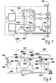
- An IPT battery charger suitable for electric vehicles comprises a multiplicity of IPT pick-up coils (104 in Figs I and 2, 304 in Fig 3) in the vehicle with each coil preferably provided with a ferrite flux-enhancement core to collect more flux, and tuned by means of a resonant capacitor 305 to a common operating frequency.
- the pick-up coils are powered from the inductive field surrounding a line or loop or coil of litz wire 103 buried in the roadway (or in the floor of a garage or parking place).
- the primary is preferably also resonant, and typical values for primary Q are 1.5 to 3.
- a generic circuit for powering a primary inductive pathway of any size is given below the label 101 in Fig 8.
- the primary coil is powered from an adequate high-frequency power supply 101 and preferably this can generate perhaps 40 kW for charging a bus-sized vehicle at 10 kHz which is a preferred frequency at this time.
- Presently available switching devices are unduly expensive for higher frequencies than 10 kHz, yet higher frequencies permit more compact inductive power transfer devices.
- the primary conductor does not need to be resonant but it is useful (for reducing radiation of harmonics and for easily generating a high-frequency current) if it is resonant.
- the primary windings are preferably contained in a concrete or other slab 202 so that the coil is some distance above the rolling surface for the vehicle.
- the coils may be embedded in slits in the floor or roadway and may protrude (inside a mechanically protective shield) from beneath the vehicle.
- unit we may refer to single cells or to groups of perhaps 3 or 6 cells. If more than one secondary coil per unit is provided it may be possible to scatter the pickup coils about the vehicle so that the chance of intercepting an inductive field is raised and the best placed coils of a large number of options can then be selected automatically. Alternatively it may be helpful to provide wheel guides or automatic guidance or the like so that the driver of the vehicle can position the vehicle substantially over the primary windings.
- the actual air gap should be small to improve the coupling but large enough so that there is no risk of physical interference between the concrete slab and the pick-up coils. In practice a gap of say 75 mm would suffice and allow for interference-free charging even if the vehicle had one flat tyre.
- a typical pickup would have a ferrite flux concentrator that is typically 250-400 mm across and 100 mm long.
- each secondary pickup unit examples of which are shown in Fig 3 as 301, or 302, or 303, has the usual pickup coil 304 (or 104 in Figs 1 and 2), and a ferrite flux concentrating core shown as 201 in Fig 2, or in section as 201 in Fig 6.
- a resonating capacitor 305 forms a resonant circuit with the pickup coil.
- a shorting device here by way of example a pair of opposed silicon-controlled rectifiers 306 is employed in order to enable, or to disable (when shorted) the pickup device, so allowing independent control of each pickup unit 301, 302, or 303.
- a shorted pickup device provides no output power and, having at that time no circulating currents either, presents no barrier to the passage of primary power in the primary conductor past the site of the shorted pickup.
- each pick-up After passing through an optional stepdown transformer 307 (for we expect that it will be more efficient to have high circulating voltage in the secondary windings) the output of each pick-up is rectified by a Schottky rectifier bridge 308 or the like and allowed to charge one of the monoblocks in the vehicle's battery.
- FIG 4 shows a control winding 304 and a power collection winding 402 in a relatively tightly coupled relationship; here sharing a ferrite core 401.
- the control winding has a relatively large number of turns, so providing a high voltage and needing a smaller resonating capacitor to meet a given resonant frequency than a power coil providing a low voltage (3-15V at perhaps 200 A)
- the control winding is equipped with a shorting switch of relatively low current capacity, such as a pair of silicon controlled rectifier units 306 in reverse parallel, or perhaps a rectifying bridge connected to a single power FET or the like.
- the non-resonant high-current winding 402 may have one or a few turns, and current from the high-current winding is directly rectified (Schottky bridge 308, discrete units 503 and 503R (reverse)), and passed to the battery unit.
- Schottky bridge 308 discrete units 503 and 503R (reverse)
- the resonant winding When the resonant winding is in a shorted state it has the effect of shielding the high-current winding from the inductive field, so halting power transfer. Shorting is an effective method for limiting peak secondary resonating currents which may interact with primary current transfer, and to interrupt the battery charge process once a suitable level of charge has been reached.
- a physical layout for a battery-charging inductive pickup is shown in Figs 5 (top view) and 6 (cross-section along the lines A--A').
- FIG 5 we have not included the control windings for the sake of clarity.
- a first version of the power winding comprises a single turn composed of copper sheet, having lugs at each end that project sideways from the pickup assembly and connect with stud rectifiers 503, and 503R.
- stud rectifiers 503, and 503R Preferably these are the Schottky type or similar, offering fast recovery and low forward voltage drop.
- These stud rectifiers are orientated so that a bridge rectifier configuration, is provided.
- the aluminium sheets 501 and 502 have the functions of (a) providing a connection point for the DC output (at holes 504 and 505), (b) providing heat dissipation from the rectifier diodes 503, 503R bolted onto it, (c) reflecting magnetic flux downwards and onto the ferrite core (and so shielding the regions above), and (4) providing support for the control unit (not shown.
- Fig 6 does include the control winding, here shown in section 304 on both sides of the power winding 402, and both wound over the ferrite elements 401 of a flux-collecting assembly of ferrite modules which may be a series of fingers, or larger lumps as shown here.
- 103 represents three conductors of a primary conductor, creating a magnetic flux for collection by the inductive pickup.
- Level 1 In this industry charging speeds are referred to as “Level 1", for an overnight kind of "trickle” charge over 8 to 15 hours, “Level 2” for a 3-8 hour charge, and “Level 3” for a fast charge taking only 10-20 minutes. Slow charges are generally better for the batteries, though different kinds of batteries can tolerate markedly different charging rates. Level 1 presents a smaller load to the electric utility supply, but could take inconveniently long.
- a charging level or speed according to the type of power available at a site. A home would generally be limited to 1.5-2.5 kVA from a single phase, 117 or 230 V outlet.
- a three-phase outlet could be provided as an alternative and cater for Level 2 charging rates; three-phase 220 to 480V power in domestic housing is infrequent but can be installed.
- Under-road installations, for "topping up" a charge as the vehicle proceeds along a road or is held up in a queue of traffic may be somewhere between Level 2 and Level 3 in order to balance the likely city usage of an EV which is sometimes within a charging inductive field or sometimes away from it.
- Three-phase power is already available in most city streets.
- the absence of a core in the primary side allows the circulating current to rise without risk of saturation, and the highest rate of charging that can be provided at any site can be set somewhere between a level 1 condition and a level 3 condition simply by controlling the amount of circulating current flowing in the primary, which in turn determines the current that the constant-current secondary can supply, without the use of further switches or inefficient regulators.
- the shorting switch approach used in these inductive power transfer circuits is a low-loss switch.
- each vehicle would presumably be fitted with means to log and charge for its electricity consumption
- An on-board meter through which power from all sources - home charging bay or under-freeway "top-ups" flows and is logged - and paid for from time to time may be used, but this could be interfered with.
- a fixed meter at the primary side is used together with a protocol involving interrogating a transponder within the vehicle in order to ascertain its identity and credit rating, moving the power, and then notifying the power utility company of the transaction. The user is charged for the increase in power consumption over the base rate, and under this arrangement inefficiencies in transfer are the responsibility of the user.
- Typical charging currents may be of the order of 180 A for a monoblock comprising a 6 or a 12 volt set of cells. This corresponds to a charging power of 2 or 3kW.
- each lead-acid battery monoblock is charged independently so each one can be charged to the 30% DOD every time (conditions permitting) and no more. A charge equalising procedure may not be needed.
- the loosely coupled IPT technique allows this option to be achieved at reasonable cost whereas otherwise it would be prohibitively expensive.
- the supply to the battery is at substantially a constant current which can be tailored to suit the requirements of the monoblock by physical design or by primary current control, rather than by active control with series or shunt regulators.
- Each monoblock can be switched hard on or hard off by shorting its resonant circuit (a procedure which involves surprisingly little current sinking) and can be regulated as a "bang-bang" controller.
- the charging current for a 40 kW bus application might be about 170 A per six volt monoblock.
- the microprocessor will repeatedly assess the current flowing through each individual monoblock and compare this with instructions passed through an optically isolated RS485 link (313) so that the modes of all microprocessors can be changed if required and so that fault reports, trends in battery unit condition, and the like can be made available.
- each controller could work alone.
- Lead-acid batteries are at present marginally acceptable for EV applications and suffer from many disadvantages, thus a battery management system that can optimise their performance is likely to be fundamental to making an EV an economic proposition.
- the current thinking is that the batteries can be cycled between 30% and 70% depth of discharge (DOD) for a virtually unlimited number of cycles. Deeper discharge is likely to cause problems (although from time to time it may inevitably occur) and higher charges are also a problem both with respect to cycle life and with charging rates which must be reduced or the battery will overheat.
- DOD depth of discharge
- the equalising controller can conveniently read the voltages of a series of these through a multi-channel A-D input. If each cell has its own source of charging voltage, these can then be controlled so that the entire battery bank is maintained at a consistent level of charge.
- An equalising controller may adjust individual cells relative to each other within a monoblock. It may equalise by providing supplementary charging currents (say 10% of the working currents) to those cells that are lagging behind. (The equalising controller is described below in more detail). It may however be optimal to regard the minimum unit as a monoblock of a 6 or a 12 volt set of cells.
- Charge assessment may be by inferring internal resistance measurement, by examining the electrolyte, or by other means more appropriate to a preferred type of storage battery. If the current resonating in the secondary coil rises too much and may re-radiate an inductive field that can interfere with primary current flow, the shorting switch can be closed so that the secondary current is halted. Normally the microprocessor will endeavour to return the monoblock to 70% of maximum charge and then hold the shorting switch closed, cutting off the flow of current.
- the microprocessor may then impose a nearly always ON duty cycle initially, and finishing up with a nearly always OFF cycle. Voltage and current measurements during charge, and voltage measurements during the OFF portions of the cycle will indicate to the controller the state of charge.
- Each monoblock would further have its own microprocessor to monitor the charge and record the coulombmetric efficiency so that accurate records would be available to spot errant cells.
- Lead-acid batteries can be brought up to a fuller charge using pulse charging rather than steady currents. The battery could be cycled through several cycles always coming up to the 30% DOD but measuring the on-charge and off-charge voltages to keep records of its dynamic resistance. Alternatively there might be a requirement to override the 30% level and force a full charge.
- the whole charging process would be completely 'intervention-free'.
- a system for billing the appropriate customer for electricity consumed may be included. Faulty cells can be identified even before failure, perhaps as an increase in internal resistance. Failed cells may be taken out of the bank either by manual disconnection/bridging or by automatic disconnection.
- a monoblock incorporating this invention can be termed a self-stabilising or a charge-balancing monoblock.
- the invention can be applied to forms of storage battery that are not packaged as monoblocks - for example large banks of large cells such as are used in telephone exchanges can also be stabilised in the same way.
- An external charger (which may also be driven by inductive power) provides most of the charge while the self-stabilising feature provides a small amount - perhaps 5% - more charge to those cells that remain under-charged, typically taking the energy from the bank as a whole. Even during discharge, a cell that is discharging more quickly than the average rate can be supplemented by drawing current from other cells within the monoblock.
- a self-stabilising monoblock could be always stabilising itself when in use, or when on the shelf (unless the stabilising feature is disabled).
- One simple disabling control may be to turn off a lamp connected to an optical fibre 708 received in an optical receiver module that has the effect of disabling a power converter 101 in Fig 8.
- the optical fibre can be used for more sophisticated communications such as reporting on the status of individual cells, reporting current drain, and the like. Note that in both Figs 7 and 8 only some cells and associated modules are shown for simplicity. While in Fig 8 only one module 808 is shown (wherein the cell 705 is one part of the monoblock 309) there would in practice be typically six units each like 808 having a control and a power winding on a physically and inductively separate pickup core.
- a self-stabilising monoblock according to the invention includes a resonant converter (Figs 7 & 8 - 101) to convert DC, usually obtained from across all the cells of the monoblock 309, into AC at perhaps 10 to 50 kHz.
- the converter shown in Fig 8 draws DC power through a series inductor 802 to render the input a current source, and a centre-tapped DC splitting inductor 806.
- the primary inductive conductor may in a car-battery sized monoblock be conceptual - a set of inductors may be positioned upon a single circuit board so that each one can be separately controlled by internal shorting without affecting nearby modules, and sense (702) and charging (707) conductors are taken from the board to reach all between-cell connectors. These conductors allow for separately charging and for monitoring individual cells and there may be one or more temperature sensors as well, because if voltage is used as the discriminant of charge status, temperature has an effect on readings. If on the other hand the monoblock is large the primary conductor 103 may be extended over tens or hundreds of metres.
- the monoblock has as usual a positive and a negative connection (703, 704) to the outside world, and the stabilising feature may be entirely internal.
- a communications link such as an optical fibre 708 could be provided for control (eg disabling during long-term storage) or for reporting purposes; such as for notifying the existence of a faulty cell to a logging means.
- battery manufacturers prefer not to provide extra connectors to a monoblock, so that a sealed-in set of electronics is likely to be preferred. Effective potting also protects the electronics from exposure to corrosive electrolyte. The expense of providing sealed-in electronics of this type is compensated for by increased battery life.
- replication of circuits should provide economy of scale. It should be noted that some individual cells are very large, such as those used in telephone exchanges for a DC supply, yet the same circuitry can be used.
- a controller 701 is preferably provided to manage the internal parts of a monoblock. In one embodiment, it would be provided with inputs 702 including the voltage across each cell and the monoblock temperature, preferably also at least a total current measure if not also the charging current fed to each monoblock. Current measurement may allow internal resistance to be measured, or allow cell voltage to be measured even when under load. Typically there would also be controls 708 from the outside world so that the resonant converter can be inhibited for example. Outputs from the controller include a line to separately inhibit each individual charger (by shorting it at 306).
- One advantage of the invention is that the inhibit line, taken to the gate of a shorting switch, can be floating with respect to the particular cell to be charged.
- this controller would be a conventional microprocessor having analogue inputs and a program memory holding an operating program.
- a separate controller 701 may be provided for each cell, more likely if individual cells are large or if the cost of a separate controller is less than the complexity of providing inputs from and controls to a bank of modules each running at a separate offset voltage.
- the internal stabilisation charging may be disabled, but preferably the sensing means is still capable of reporting whether or not the average of the monoblock has reached 30% DOD during a charging operation, so that charging of that monoblock can be halted.
- the internal controller in the monoblock would review all cell voltages in relation to temperature and regard any low voltages as indicating cells which are not sufficiently charged. It would then apply an extra charging current to those cells, checking the state of charge from time to time, and drawing power from the bank of cells within that monoblock itself. A process of this type is described in more detail in the previous section.
- This balancing procedure may also be used during the consumption of power from the monoblock, so that no cell is discharged by too great an amount, although it may be sufficient to apply the self-stabilising feature only after an identified charging procedure. In some applications, normal use may immediately follow a charging session, so preferably the stabilisation method can be functional during use in whatever operating conditions are expected.
- the controller may be equipped with reporting means to alert an external supervisor that a certain cell is faulty and may be replaced.
- entire monoblocks are usually replaced because of premature failure of unidentified single cells. If replacement can be focused on the failed cell, overall life is increased.
- the controller may at least be provided with an inhibit feature so that it halts the resonant power converter and puts the microprocessor into a sleep mode during periods when the monoblock is not in use.
- the main advantage of this self-stabilising feature is that no cell is allowed to drift in its charge from between 30% and 70% depth of discharge. All cells are always used within their best range of charge and so battery life is extended. In present-day applications the problem is generally avoided by overcharging so that all cells eventually can take no more charge, but that involves gas release and the adverse effects of electrolyte depletion, causes overheating, violates the 30 to 70% DOD life-enhancing practice, and consumes a significant amount of extra time and energy.
- Inductively transferred electric power in a loosely coupled system as described in this specification inherently comprises a current source which is preferable to a voltage source for battery charging purposes. Additional components to convert a voltage source into a current source are not required; saving in cost and in efficiency and permitting replication for single-cell delivery and control.
- Each module (as per Fig 4) can be electrically isolated so that a number (which may be 20) of identical modules may be used simultaneously to charge an entire bus battery bank running on nominally 240V DC (prior to conversion).
- the pickup uses a shorting system for control, which is efficient and which allows more than one module at a time to draw power from the same primary conductor, so that one source of power can be used to charge up an entire battery bank using multiple charging units.
- the controller can closely control the charge in each cell so that all cells are limited to a 30-70% depth of discharge in normal operation, so extending the life of the battery and/or allowing battery design to be optimised for this pattern of use.
- a "self-stabilising monoblock” intended as a replacement for a conventional monoblock internally duplicates the above IPT circuitry. When (optionally) operating in a self-contained environment it can adjust the charge in one cell at the expense of the others.
Landscapes
- Engineering & Computer Science (AREA)
- Power Engineering (AREA)
- Transportation (AREA)
- Mechanical Engineering (AREA)
- Life Sciences & Earth Sciences (AREA)
- Sustainable Development (AREA)
- Sustainable Energy (AREA)
- Computer Networks & Wireless Communication (AREA)
- Charge And Discharge Circuits For Batteries Or The Like (AREA)
- Secondary Cells (AREA)
Claims (12)
- Ein Batterielademittel für eine aus einer oder mehreren Zellen (705) bestehenden Batterie-Einheit (309);
wobei vom Batterielademittel induktive Stromübertragung zwischen einem Primärinduktivleiter (103), der mit hoher Frequenz unter Strom gesetzt werden kann, und einem resonanten, sekundären Induktivaufnehmer (301, 302, 303), der in der Lage ist, eine entsprechende Batterie-Einheit mit Ladestrom zu versorgen, eingesetzt wird;
besagter Aufnehmer über mindestens eine erste Steuemngsinduktionsspule (304) und eine zweite Stromumschlags-Induktionsspule (402), die induktiv miteinander verbunden sind, sowie einen Resonanzkondensator (305) und Einstellmittel (308) verfügt;
wobei der Aufnehmer (301, 302, 303) über ein Mittel (306) zur Verstellung der Kopplung zwischen dem Primärinduktivleiter (103) und dem Induktivaufnehmer (301, 302, 303) verfügt; das Mittel aus einem Kurzschlussschalter (306) besteht, der in der Lage ist, die erste Steuerungsinduktionsspule (304) von Zeit zu Zeit kurzzuschließen, sodass die im Resonanzaufnehmer (301, 302, 303) zirkulierende Strommenge gesteuert werden kann und die der wiederaufladbaren Batterie-Einheit (309) zugeführte Strommmenge gesteuert werden kann, indem die stromumschlagende zweite Induktionsspule (402) vom Primärinduktivleiter (103) abgekoppelt wird. - Batterielademittel wie in Anspruch 1, dadurch gekennzeichnet, dass der Induktivaufnehmer (301, 302, 303) über Steuermittel (701) verfügt, die die Kopplungsintensität zwischen dem Primärinduktivleiter (103) und jeder der Aufnehmerwieklungen (304) steuern;
wobei die Steuermittel (701) in der Lage sind, den Ladestatus der wiederaufladbaren Batterie (309) zu ermitteln und weiteren Ladestrom zuzuführen oder nicht zuzuführen, sodass der Ladestatus der wiederaufladbaren Batterie gesteuert werden kann. - Batterietademittel wie in Anspruch 2 zum Einsatz mit mindestens einem Primärinduktivleiter (103) und einem Satz wiederaufladbarer Batterien (705), der aus einer Vielzahl von Batterie-Einheiten (309) besteht;
wobei jede Batterie-Einheit mit angegliederten Batterielademitteln versehen ist, dadurch gekennzeichnet, dass das Steuermittel (701) in der Lage ist, den Ladestatus jeder Batterie-Einheit des Satzes zu ermitteln und zusätzlichen Ladestrom entweder zuzuführen oder zu sperren kann, sodass der Ladestatus der entsprechenden Batteric-Einheit gesteuert wird und der Ladestatus über alle Batterie-Einheiten des gesamten Batteriesatzes gleichgestellt wird. - Ein Batterie-Monoblock (309), bestehend aus einer Vielzahl einzelner Zellen (705) und einer Vielzahl angegliederter Batterielademittel gemäss Anspruch 3, dadurch gekennzeichnet, dass das Lade- und Steuermittel (701) in der Lage ist, seinen Betriebsstrom intern zu beziehen und der Monoblock, der die Lade- und Kontrollmittel enthält, eine selbst-stabilisierende Funktion aufweist, mittels der das Steuermittel (701) in der Lage ist, zu ermitteln, ob eine einzelne Zelle im Vergleich zu einer anderen Zelle mit weniger Ladung beaufschlagt ist, und das Steuermittel dann in der Lage ist, jeder minderbeaufschlagten Zelle Ladung zuzuführen, sodass alle Zellen auf den gleichen Ladezustand gebracht werden.
- Ein Batterie-Monoblock gemäss Anspruch 4, dadurch gekennzeichnet, dass das Lade- und Steuermittel physisch im Monoblock untergebracht ist.
- Ein Fahrzeug, das mindestens teilweise von mindestens einem Elektromotor angetrieben wird, dadurch gekennzeichnet, dass der Elektromotor seinen Strom von einem Satz wiederaufladbarer Batterien bezieht, die mit einem Batterielademittel gemäss Anspruch 3 geladen werden können.
- Ein Speichermodul für elektrischen Strom einschliesslich von Stromaufnahmemitteln, die Strom von einer erneuerbaren Energiequelle aufzunehmen in der Lage sind, und eines wiederaufladbaren Batteriesatzes (309), der in der Lage ist, die aufgenommene Energie zu speichern und sie einem Stromumwandlungsgerät zuzuführen, das dadurch gekennzeichnet ist, dass der wiederaufladbare Batteriesatz mit Batterielade- und Steuermitteln gemäss Anspruch 3 geladen werden kann.
- Ein Fahrzeug gemäss Anspruch 6, dadurch gekennzeichnet, dass der Elektromotor Strom von einem wiederaufladbaren Batteriesatz bezieht, der von Batterielademitteln gemäss Anspruch 4 geladen werden kann.
- Ein Speichermodul für elektrischen Strom gemäss Anspruch 7, dadurch gekennzeichnet, dass der wiederaufladbare Batteriesatz von Batterielade- und Steuermitteln gemäss Anspruch 4 geladen werden kann.
- Batterielademittel gemäss Anspruch 2, dadurch gekennzeichnet, dass es sich bei der wiederaufladbaren Batterie um eine Bleibatterie handelt und das Steuermittel (701) im wesentlichen die Ladung zwischen vorbestimmten Grenzwerten hält, namentlich einer Obergrenze von 70% der vollen Ladung und einer Untergrenze von 30% der vollen Ladung, sodass die Bleibatterie eine verbesserte Nutzungsdauer aufweist.
- Batterielademittel gemäss Anspruch 2, dadurch gekennzeichnet, dass das Steuermittel (701) in der Lage ist, Ausfälle im wiederaufladbaren Batteriesatz zu erkennen oder vorauszusehen.
- Batterielademittel gemäss Anspruch 2, dadurch gekennzeichnet, dass das Steuermittel (701) in der Lage ist, die Leistung der oder jeder Batterie-Einheit aufzuzeichnen.
Applications Claiming Priority (5)
| Application Number | Priority Date | Filing Date | Title |
|---|---|---|---|
| NZ28651396 | 1996-05-03 | ||
| NZ28651396 | 1996-05-03 | ||
| NZ299396 | 1996-09-17 | ||
| NZ29939696 | 1996-09-17 | ||
| PCT/NZ1997/000053 WO1997042695A1 (en) | 1996-05-03 | 1997-05-02 | Inductively powered battery charger |
Publications (3)
| Publication Number | Publication Date |
|---|---|
| EP0896758A1 EP0896758A1 (de) | 1999-02-17 |
| EP0896758A4 EP0896758A4 (de) | 2001-04-11 |
| EP0896758B1 true EP0896758B1 (de) | 2006-03-29 |
Family
ID=26651608
Family Applications (1)
| Application Number | Title | Priority Date | Filing Date |
|---|---|---|---|
| EP97920994A Expired - Lifetime EP0896758B1 (de) | 1996-05-03 | 1997-05-02 | Induktiv gespeister batterielader |
Country Status (7)
| Country | Link |
|---|---|
| US (1) | US6100663A (de) |
| EP (1) | EP0896758B1 (de) |
| JP (1) | JP2000509955A (de) |
| AU (1) | AU716214B2 (de) |
| CA (1) | CA2252224A1 (de) |
| DE (1) | DE69735586D1 (de) |
| WO (1) | WO1997042695A1 (de) |
Cited By (1)
| Publication number | Priority date | Publication date | Assignee | Title |
|---|---|---|---|---|
| DE102020108363A1 (de) | 2020-03-26 | 2021-09-30 | Bayerische Motoren Werke Aktiengesellschaft | Ladeadapter zum Laden einer Fahrzeugbatterie |
Families Citing this family (116)
| Publication number | Priority date | Publication date | Assignee | Title |
|---|---|---|---|---|
| DE19836401A1 (de) * | 1997-09-19 | 2000-02-17 | Salcomp Oy Salo | Vorrichtung zum Aufladen von Akkumulatoren |
| GB9724423D0 (en) * | 1997-11-19 | 1998-01-14 | Ackermann Ltd | Office workstation services |
| EP0921607A3 (de) * | 1997-11-21 | 2000-02-23 | Miltronik GmbH & Co. KG | Steckverbindung zum Übertragen von Daten zwischen einer elektrischen Spannungsquelle und einer Datenverarbeitungseinrichtung |
| JP3506006B2 (ja) | 1998-05-27 | 2004-03-15 | 株式会社ダイフク | 無接触給電設備の2次側受電回路 |
| US9425638B2 (en) | 1999-11-01 | 2016-08-23 | Anthony Sabo | Alignment independent and self-aligning inductive power transfer system |
| US7263388B2 (en) * | 2001-06-29 | 2007-08-28 | Nokia Corporation | Charging system for portable equipment |
| US6906495B2 (en) * | 2002-05-13 | 2005-06-14 | Splashpower Limited | Contact-less power transfer |
| GB0210886D0 (en) | 2002-05-13 | 2002-06-19 | Zap Wireless Technologies Ltd | Improvements relating to contact-less power transfer |
| CN100550570C (zh) * | 2002-05-13 | 2009-10-14 | 捷通国际有限公司 | 电能传输系统和在其中使用的初级装置 |
| GB2399228B (en) * | 2002-05-13 | 2006-01-04 | Splashpower Ltd | Inductive power transfer system having uniform coupling |
| GB2388716B (en) | 2002-05-13 | 2004-10-20 | Splashpower Ltd | Improvements relating to contact-less power transfer |
| US20080108372A1 (en) * | 2002-06-11 | 2008-05-08 | Intelligent Technologies International, Inc. | Inductively Powered Asset Monitoring System |
| DE50301225D1 (de) * | 2003-04-04 | 2005-10-27 | Ford Global Tech Llc | Anordnung zur Stromversorgung eines Kraftfahrzeugs |
| US7012508B1 (en) | 2003-04-10 | 2006-03-14 | Briggs & Stratton Corporation | System and method for controlling a door |
| US20090284384A1 (en) * | 2003-05-03 | 2009-11-19 | Barton Robert A | Unobtrusive Power Failure Lighting System |
| NZ526109A (en) * | 2003-05-26 | 2006-09-29 | Auckland Uniservices Ltd | Parallel-tuned pick-up system with multiple voltage outputs |
| US7293565B2 (en) * | 2003-06-30 | 2007-11-13 | Philip Morris Usa Inc. | Electrically heated cigarette smoking system |
| US20070159279A1 (en) * | 2004-05-12 | 2007-07-12 | Ryuichi Shimada | Alternating-current power supply device recovering magnetic energy |
| US7414380B2 (en) * | 2004-09-21 | 2008-08-19 | Lear Corporation | Apparatus for inductively recharging batteries of a portable convenience device |
| US7318564B1 (en) | 2004-10-04 | 2008-01-15 | The United States Of America As Represented By The Secretary Of The Air Force | Power line sentry charging |
| US7398946B1 (en) | 2004-10-04 | 2008-07-15 | United States Of America As Represented By The Secretary Of The Air Force | Power line sentry charging |
| US7543780B1 (en) | 2004-10-04 | 2009-06-09 | The United States Of America As Represented By The Secretary Of The Air Force | Unmanned air vehicle transmission line docking surveillance |
| JP4318044B2 (ja) | 2005-03-03 | 2009-08-19 | ソニー株式会社 | 電力供給システム、電力供給装置および方法、受電装置および方法、記録媒体、並びにプログラム |
| EP1750361A1 (de) * | 2005-08-03 | 2007-02-07 | ABB Research Ltd | Anordnung eines Multilevel-Converters und ihre Verwendung |
| KR101124725B1 (ko) * | 2006-06-15 | 2012-03-23 | 한국과학기술원 | 전하 균일 장치 |
| KR101081255B1 (ko) * | 2007-02-09 | 2011-11-08 | 한국과학기술원 | 전하 균일 장치 |
| KR101124800B1 (ko) * | 2007-02-09 | 2012-03-23 | 한국과학기술원 | 전하 균일 장치 |
| JP5121307B2 (ja) * | 2007-05-28 | 2013-01-16 | ソニーモバイルコミュニケーションズ株式会社 | 無接点電力伝送コイルユニット、携帯端末、送電装置、及び、無接点電力伝送システム |
| US8030888B2 (en) * | 2007-08-13 | 2011-10-04 | Pandya Ravi A | Wireless charging system for vehicles |
| JP4453741B2 (ja) * | 2007-10-25 | 2010-04-21 | トヨタ自動車株式会社 | 電動車両および車両用給電装置 |
| WO2009076418A1 (en) * | 2007-12-11 | 2009-06-18 | Antonio Trigiani | Battery management system |
| US8487479B2 (en) * | 2008-02-24 | 2013-07-16 | Qualcomm Incorporated | Ferrite antennas for wireless power transfer |
| US8193768B2 (en) * | 2008-02-28 | 2012-06-05 | Jason S. Hallett | Contactless charging system for musical instruments |
| CN101971452B (zh) * | 2008-03-13 | 2014-06-04 | 捷通国际有限公司 | 具有多个线圈初级的感应电源系统 |
| US20090237029A1 (en) * | 2008-03-24 | 2009-09-24 | Spx Corporation | Inductive battery charger for service equipment |
| US8754611B2 (en) * | 2008-04-11 | 2014-06-17 | Apple Inc. | Diffusion-limited adaptive battery charging |
| US8024012B2 (en) * | 2008-06-11 | 2011-09-20 | International Business Machines Corporation | Intelligent wireless power charging system |
| EP2161811A1 (de) * | 2008-09-05 | 2010-03-10 | Koninklijke Philips Electronics N.V. | Induktiver Lader und Ladeverfahren |
| JP5083413B2 (ja) * | 2008-11-21 | 2012-11-28 | トヨタ自動車株式会社 | 電動車両 |
| US8616134B2 (en) | 2009-01-23 | 2013-12-31 | Magnemotion, Inc. | Transport system powered by short block linear synchronous motors |
| US8967051B2 (en) * | 2009-01-23 | 2015-03-03 | Magnemotion, Inc. | Transport system powered by short block linear synchronous motors and switching mechanism |
| US9032880B2 (en) | 2009-01-23 | 2015-05-19 | Magnemotion, Inc. | Transport system powered by short block linear synchronous motors and switching mechanism |
| WO2010102287A2 (en) * | 2009-03-06 | 2010-09-10 | Asic Advantage, Inc. | Battery charge and discharge controller |
| SE533865C2 (sv) * | 2009-04-20 | 2011-02-15 | Oestergoetlands Fastighetsservice El & Larm I Norrkoeping Ab | Varuvagn magnetslinga |
| WO2010131983A1 (en) * | 2009-05-12 | 2010-11-18 | Auckland Uniservices Limited | Inductive power transfer apparatus and electric autocycle charger including the inductive power transfer apparatus |
| US9124308B2 (en) | 2009-05-12 | 2015-09-01 | Kimball International, Inc. | Furniture with wireless power |
| US8061864B2 (en) | 2009-05-12 | 2011-11-22 | Kimball International, Inc. | Furniture with wireless power |
| FR2947113A1 (fr) * | 2009-06-17 | 2010-12-24 | Renault Sas | Charge d'une batterie de vehicule automobile |
| FR2947114B1 (fr) * | 2009-06-17 | 2014-09-19 | Renault Sas | Charge d'une batterie de vehicule automobile |
| US8237402B2 (en) * | 2009-10-08 | 2012-08-07 | Etymotic Research, Inc. | Magnetically coupled battery charging system |
| US8022775B2 (en) * | 2009-10-08 | 2011-09-20 | Etymotic Research, Inc. | Systems and methods for maintaining a drive signal to a resonant circuit at a resonant frequency |
| US8174233B2 (en) * | 2009-10-08 | 2012-05-08 | Etymotic Research, Inc. | Magnetically coupled battery charging system |
| US8460816B2 (en) * | 2009-10-08 | 2013-06-11 | Etymotic Research, Inc. | Rechargeable battery assemblies and methods of constructing rechargeable battery assemblies |
| US8174234B2 (en) * | 2009-10-08 | 2012-05-08 | Etymotic Research, Inc. | Magnetically coupled battery charging system |
| US8228027B2 (en) * | 2009-10-13 | 2012-07-24 | Multi-Fineline Electronix, Inc. | Wireless power transmitter with multilayer printed circuit |
| WO2011046223A1 (ja) | 2009-10-14 | 2011-04-21 | Udトラックス株式会社 | 蓄電装置 |
| US8538614B1 (en) * | 2009-12-07 | 2013-09-17 | T3 Motion, Inc. | Rechargeable battery systems and methods |
| US8427102B2 (en) * | 2009-12-17 | 2013-04-23 | Motorola Mobility Llc | Dynamic current limiting charging circuit |
| US20110193518A1 (en) * | 2010-02-10 | 2011-08-11 | James Wright | Battery override |
| US20110238341A1 (en) * | 2010-03-25 | 2011-09-29 | Mehdi Etezadi-Amoli | High Power DC Kilowatt Hour Meter |
| WO2011145953A1 (en) * | 2010-05-19 | 2011-11-24 | Auckland Uniservices Limited | Inductive power transfer system primary track topologies |
| DE102010021707B4 (de) | 2010-05-27 | 2024-05-02 | Sew-Eurodrive Gmbh & Co Kg | Anordnung und Verfahren zum Betreiben einer Anordnung |
| US8841881B2 (en) | 2010-06-02 | 2014-09-23 | Bryan Marc Failing | Energy transfer with vehicles |
| US9182448B2 (en) * | 2010-06-04 | 2015-11-10 | Toyota Jidosha Kabushiki Kaisha | Secondary battery, inspection apparatus and inspection method for secondary battery, and battery inspection system |
| JP5562804B2 (ja) * | 2010-11-02 | 2014-07-30 | 昭和飛行機工業株式会社 | インダクタンス可変の非接触給電装置 |
| JP5844631B2 (ja) * | 2010-12-15 | 2016-01-20 | 東海旅客鉄道株式会社 | 受電装置、及び受電方法 |
| CN103262387B (zh) | 2010-12-24 | 2016-08-17 | 丰田自动车株式会社 | 非接触充电系统和方法、车辆、以及非接触充电管理装置 |
| CN102075016A (zh) * | 2010-12-24 | 2011-05-25 | 杭州华宁科技有限公司 | 一种便携式绝缘充电方法及其设备 |
| JP5836598B2 (ja) * | 2011-01-19 | 2015-12-24 | 株式会社テクノバ | 非接触給電用コア |
| US9306634B2 (en) | 2011-03-01 | 2016-04-05 | Qualcomm Incorporated | Waking up a wireless power transmitter from beacon mode |
| KR101229441B1 (ko) * | 2011-03-18 | 2013-02-06 | 주식회사 만도 | 배터리 충전 장치 |
| KR101668925B1 (ko) | 2011-06-07 | 2016-10-24 | 마그네모션, 인코포레이티드 | 선형 동기 모터 추진 시스템의 다목적 제어 |
| DE102011103439B3 (de) * | 2011-06-07 | 2012-08-30 | Audi Ag | Kraftfahrzeug mit einem Speicher für elektrische Energie, der induktiv über eine Spule geladen wird, dessen Gehäuse eine Vorrichtung zur Erkennung von Beschädigungen umfasst |
| WO2012172468A2 (en) * | 2011-06-11 | 2012-12-20 | Sendyne Corp. | Charge redistribution method for cell arrays |
| TWI425738B (zh) * | 2011-08-12 | 2014-02-01 | 富達通科技股份有限公司 | Vehicle induction charging method |
| TW201336200A (zh) * | 2012-02-16 | 2013-09-01 | 國立成功大學 | 串聯電池電量平衡充/放電電路及其控制方法 |
| US9998179B2 (en) * | 2012-03-09 | 2018-06-12 | Auckland Uniservices Limited | Shorting period control in inductive power transfer systems |
| US20130241491A1 (en) * | 2012-03-19 | 2013-09-19 | Jianguo Hu | Balanced battery pack system based on two-way energy transfer |
| EP2845416B1 (de) | 2012-05-02 | 2018-11-21 | Apple Inc. | Verfahren zum nachweis und zur identifizierung eines empfängers in einem induktiven energieübertragungssystem |
| US9445524B2 (en) * | 2012-07-06 | 2016-09-13 | Gentherm Incorporated | Systems and methods for thermoelectrically cooling inductive charging stations |
| EP2696432B1 (de) * | 2012-08-08 | 2014-11-19 | Datang NXP Semiconductors Co., Ltd. | Energiespeicherzelle für eine Mehrfachzellen-Energiespeichervorrichtung |
| US10014104B2 (en) * | 2012-11-02 | 2018-07-03 | Qualcomm Incorporated | Coil arrangements in wireless power transfer systems for low electromagnetic emissions |
| US9802507B2 (en) | 2013-09-21 | 2017-10-31 | Magnemotion, Inc. | Linear motor transport for packaging and other uses |
| WO2015084587A1 (en) | 2013-12-03 | 2015-06-11 | Massachusetts Institute Of Technology | Method and apparatus for wirelessly charging portable electronic devices |
| KR102035307B1 (ko) | 2013-12-30 | 2019-10-22 | 주식회사 위츠 | 충전 장치 및 배터리 장치 |
| US9673658B2 (en) * | 2014-03-06 | 2017-06-06 | Samsung Electro-Mechanics Co., Ltd. | Non-contact capacitive coupling type power charging apparatus and non-contact capacitive coupling type battery apparatus |
| US10664772B1 (en) | 2014-03-07 | 2020-05-26 | Steelcase Inc. | Method and system for facilitating collaboration sessions |
| US9716861B1 (en) | 2014-03-07 | 2017-07-25 | Steelcase Inc. | Method and system for facilitating collaboration sessions |
| US9766079B1 (en) | 2014-10-03 | 2017-09-19 | Steelcase Inc. | Method and system for locating resources and communicating within an enterprise |
| US9380682B2 (en) | 2014-06-05 | 2016-06-28 | Steelcase Inc. | Environment optimization for space based on presence and activities |
| US9955318B1 (en) | 2014-06-05 | 2018-04-24 | Steelcase Inc. | Space guidance and management system and method |
| US10614694B1 (en) | 2014-06-06 | 2020-04-07 | Steelcase Inc. | Powered furniture assembly |
| US10433646B1 (en) | 2014-06-06 | 2019-10-08 | Steelcaase Inc. | Microclimate control systems and methods |
| US11744376B2 (en) | 2014-06-06 | 2023-09-05 | Steelcase Inc. | Microclimate control systems and methods |
| KR101659162B1 (ko) * | 2014-09-11 | 2016-09-22 | 삼성전기주식회사 | 비접촉 방식 충전 장치 |
| US9852388B1 (en) | 2014-10-03 | 2017-12-26 | Steelcase, Inc. | Method and system for locating resources and communicating within an enterprise |
| US10733371B1 (en) | 2015-06-02 | 2020-08-04 | Steelcase Inc. | Template based content preparation system for use with a plurality of space types |
| US10498160B2 (en) | 2015-08-03 | 2019-12-03 | Massachusetts Institute Of Technology | Efficiency maximization for device-to-device wireless charging |
| CN108401471B (zh) | 2015-11-19 | 2021-06-25 | 苹果公司 | 感应式电力发射器 |
| US9921726B1 (en) | 2016-06-03 | 2018-03-20 | Steelcase Inc. | Smart workstation method and system |
| DE102016218160A1 (de) | 2016-09-21 | 2018-03-22 | Fraunhofer-Gesellschaft zur Förderung der angewandten Forschung e.V. | Vorrichtung und Verfahren zum Zuführen von Energie zu einer Mehrzahl von Energiespeicherbauteilen und/oder zum Bereitstellen von in den Energiespeicherbauteilen gespeicherter Energie |
| US10264213B1 (en) | 2016-12-15 | 2019-04-16 | Steelcase Inc. | Content amplification system and method |
| EP3432443B1 (de) * | 2017-07-20 | 2025-09-10 | Goodrich Actuation Systems Limited | Drahtloses stromsystem |
| US10684330B2 (en) | 2017-07-28 | 2020-06-16 | Northstar Battery Company, Llc | Systems and methods for detecting thermal runaway of a battery |
| US11018526B2 (en) | 2018-02-08 | 2021-05-25 | Massachusetts Institute Of Technology | Detuning for a resonant wireless power transfer system including cooperative power sharing |
| US10651687B2 (en) | 2018-02-08 | 2020-05-12 | Massachusetts Institute Of Technology | Detuning for a resonant wireless power transfer system including cryptography |
| ES2884140T3 (es) * | 2018-07-30 | 2021-12-10 | Belenos Clean Power Holding Ag | Unidad y sistema de equilibrado inalámbrico para celda de batería |
| US10840707B2 (en) | 2018-08-06 | 2020-11-17 | Robert M. Lyden | Utility pole with solar modules and wireless device and method of retrofitting existing utility pole |
| US11207988B2 (en) | 2018-08-06 | 2021-12-28 | Robert M. Lyden | Electric or hybrid vehicle with wireless device and method of supplying electromagnetic energy to vehicle |
| US11588421B1 (en) | 2019-08-15 | 2023-02-21 | Robert M. Lyden | Receiver device of energy from the earth and its atmosphere |
| US11283363B2 (en) * | 2019-08-26 | 2022-03-22 | Ravisekhar Nadimpalli Raju | Modular power conversion system with galvanic insulation |
| US12118178B1 (en) | 2020-04-08 | 2024-10-15 | Steelcase Inc. | Wayfinding services method and apparatus |
| US11984739B1 (en) | 2020-07-31 | 2024-05-14 | Steelcase Inc. | Remote power systems, apparatus and methods |
| US12626851B2 (en) | 2021-07-04 | 2026-05-12 | The Research Foundation For The State University Of New York | High frequency integrated planar magnetics for a bidirectional AC to DC CLLC resonant converter |
| KR20240088985A (ko) | 2021-09-23 | 2024-06-20 | 매소나이트 코포레이션 | 배터리 충전을 위한 충전식 배터리를 구비한 도어 어셈블리, 방법 및 시스템 |
| EP4679661A1 (de) * | 2024-07-11 | 2026-01-14 | Fabrimex X-Tec AG | Vorrichtung zum laden einer reihenschaltung von akkumulatoren und speichervorrichtung, die mindestens eine solche vorrichtung und eine reihenschaltung von akkumulatoren umfasst, sowie entsprechendes verfahren |
Family Cites Families (12)
| Publication number | Priority date | Publication date | Assignee | Title |
|---|---|---|---|---|
| US4331911A (en) * | 1978-05-22 | 1982-05-25 | Park Robert H | Method of equalizing the voltages of the individual cells of storage batteries |
| US4523192A (en) * | 1981-12-17 | 1985-06-11 | International Computers Limited | Data processing network |
| US4496896A (en) * | 1983-04-14 | 1985-01-29 | Towmotor Corporation | Vehicle battery charging apparatus |
| DE3633638A1 (de) * | 1985-10-12 | 1987-04-16 | Magtron Magneto Elektronische | Ladegeraet |
| US5293308A (en) * | 1991-03-26 | 1994-03-08 | Auckland Uniservices Limited | Inductive power distribution system |
| FR2675644B1 (fr) * | 1991-04-19 | 1993-08-27 | Valeo Equip Electr Moteur | Circuit electrique bi-tension a signalisation de defaut perfectionnee, notamment pour vehicule automobile. |
| US5254930A (en) * | 1992-06-10 | 1993-10-19 | Digital Equipment Corporation | Fault detector for a plurality of batteries in battery backup systems |
| US5646504A (en) * | 1994-04-15 | 1997-07-08 | Feldstein; Robert S. | Magnetically balanced multi-output battery charging system |
| US5498950A (en) * | 1994-04-29 | 1996-03-12 | Delco Electronics Corp. | Battery monitoring, charging and balancing apparatus |
| JPH0865904A (ja) * | 1994-06-06 | 1996-03-08 | Nippondenso Co Ltd | 電気自動車用充電装置 |
| US5594318A (en) * | 1995-04-10 | 1997-01-14 | Norvik Traction Inc. | Traction battery charging with inductive coupling |
| US5659237A (en) * | 1995-09-28 | 1997-08-19 | Wisconsin Alumni Research Foundation | Battery charging using a transformer with a single primary winding and plural secondary windings |
-
1997
- 1997-05-02 US US09/180,189 patent/US6100663A/en not_active Expired - Fee Related
- 1997-05-02 JP JP9539812A patent/JP2000509955A/ja not_active Ceased
- 1997-05-02 EP EP97920994A patent/EP0896758B1/de not_active Expired - Lifetime
- 1997-05-02 AU AU27154/97A patent/AU716214B2/en not_active Ceased
- 1997-05-02 DE DE69735586T patent/DE69735586D1/de not_active Expired - Lifetime
- 1997-05-02 CA CA002252224A patent/CA2252224A1/en not_active Abandoned
- 1997-05-02 WO PCT/NZ1997/000053 patent/WO1997042695A1/en not_active Ceased
Cited By (1)
| Publication number | Priority date | Publication date | Assignee | Title |
|---|---|---|---|---|
| DE102020108363A1 (de) | 2020-03-26 | 2021-09-30 | Bayerische Motoren Werke Aktiengesellschaft | Ladeadapter zum Laden einer Fahrzeugbatterie |
Also Published As
| Publication number | Publication date |
|---|---|
| JP2000509955A (ja) | 2000-08-02 |
| US6100663A (en) | 2000-08-08 |
| AU2715497A (en) | 1997-11-26 |
| EP0896758A1 (de) | 1999-02-17 |
| WO1997042695A1 (en) | 1997-11-13 |
| CA2252224A1 (en) | 1997-11-13 |
| AU716214B2 (en) | 2000-02-24 |
| EP0896758A4 (de) | 2001-04-11 |
| DE69735586D1 (de) | 2006-05-18 |
Similar Documents
| Publication | Publication Date | Title |
|---|---|---|
| US6100663A (en) | Inductively powered battery charger | |
| EP3163737B1 (de) | Betriebsverfahren zur drahtloses stromübertragung für eine fahrzeuganordnung | |
| EP2369712A1 (de) | Batterieladevorrichtung | |
| KR101166020B1 (ko) | 비접촉 충전 시스템 및 이를 포함한 에너지 저장 시스템 | |
| KR101955806B1 (ko) | 이물질 검출 방법, 이를 이용하는 무선 전력전송 제어 장치 및 무선 전력전송 장치 | |
| CN105375539B (zh) | 动力电池自动均衡充电器 | |
| KR101974506B1 (ko) | 전기 자동차의 하이브리드 충전 시스템 | |
| Covic et al. | Electric Vehicles–Personal transportation for the future | |
| WO1998032209A1 (en) | Method and apparatus for charging a plurality of electric vehicles | |
| US20230101550A1 (en) | Energy storage systems and methods for managing increased peak demand | |
| KR20190108957A (ko) | 전기차 무선 전력 전송 시스템에서의 브리지리스 정류기를 포함하는 전력 수신 장치 | |
| KR101974507B1 (ko) | 전기 자동차의 다상 무선 충전 시스템 | |
| US11214164B2 (en) | Method and apparatus for controlling wireless power transfer to electric vehicle using bridgeless rectifier | |
| Mamidala et al. | Grid-integrated EV charging infrastructure | |
| Shafiei et al. | Electric and plug‐in hybrid electric vehicles | |
| KR20000010733A (ko) | 유도전원 전지 충전기 | |
| Shariff | Single-phase robust charger with high power quality for electric vehicle application | |
| Mathuria et al. | Introduction to EV Charging Systems | |
| Elshora | Design and analysis of multiple input non-isolated DC-DC converter for fast charging station of electric vehicles | |
| Alqarni | Effect of the Positioning of Multiple Charging Stations for Electric Vehicles on Grid Performance in Saudi Arabia: The Case of Jeddah City | |
| Foqha et al. | Electric Vehicle Charging Infrastructures, Chargers Levels and Configurations | |
| KR20250165925A (ko) | 고전압, 저전압 배터치 충전이 가능한 통합 무선충전시스템 | |
| Carli et al. | Advanced Electric Vehicles | |
| Balamurugan et al. | EV Battery Charging System | |
| INDU | AVIDIP DEY |
Legal Events
| Date | Code | Title | Description |
|---|---|---|---|
| PUAI | Public reference made under article 153(3) epc to a published international application that has entered the european phase |
Free format text: ORIGINAL CODE: 0009012 |
|
| 17P | Request for examination filed |
Effective date: 19981002 |
|
| AK | Designated contracting states |
Kind code of ref document: A1 Designated state(s): DE DK ES FI FR GB IE IT NL SE |
|
| A4 | Supplementary search report drawn up and despatched |
Effective date: 20010223 |
|
| AK | Designated contracting states |
Kind code of ref document: A4 Designated state(s): DE DK ES FI FR GB IE IT NL SE |
|
| RIC1 | Information provided on ipc code assigned before grant |
Free format text: 7H 02J 7/00 A, 7H 02J 7/04 B, 7H 02J 7/12 B, 7H 02J 7/02 B |
|
| 17Q | First examination report despatched |
Effective date: 20041228 |
|
| GRAP | Despatch of communication of intention to grant a patent |
Free format text: ORIGINAL CODE: EPIDOSNIGR1 |
|
| GRAS | Grant fee paid |
Free format text: ORIGINAL CODE: EPIDOSNIGR3 |
|
| GRAA | (expected) grant |
Free format text: ORIGINAL CODE: 0009210 |
|
| AK | Designated contracting states |
Kind code of ref document: B1 Designated state(s): DE DK ES FI FR GB IE IT NL SE |
|
| PG25 | Lapsed in a contracting state [announced via postgrant information from national office to epo] |
Ref country code: NL Free format text: LAPSE BECAUSE OF FAILURE TO SUBMIT A TRANSLATION OF THE DESCRIPTION OR TO PAY THE FEE WITHIN THE PRESCRIBED TIME-LIMIT Effective date: 20060329 Ref country code: IT Free format text: LAPSE BECAUSE OF FAILURE TO SUBMIT A TRANSLATION OF THE DESCRIPTION OR TO PAY THE FEE WITHIN THE PRESCRIBED TIME-LIMIT;WARNING: LAPSES OF ITALIAN PATENTS WITH EFFECTIVE DATE BEFORE 2007 MAY HAVE OCCURRED AT ANY TIME BEFORE 2007. THE CORRECT EFFECTIVE DATE MAY BE DIFFERENT FROM THE ONE RECORDED. Effective date: 20060329 |
|
| REG | Reference to a national code |
Ref country code: GB Ref legal event code: FG4D |
|
| PG25 | Lapsed in a contracting state [announced via postgrant information from national office to epo] |
Ref country code: IE Free format text: LAPSE BECAUSE OF NON-PAYMENT OF DUE FEES Effective date: 20060502 |
|
| REG | Reference to a national code |
Ref country code: IE Ref legal event code: FG4D |
|
| REF | Corresponds to: |
Ref document number: 69735586 Country of ref document: DE Date of ref document: 20060518 Kind code of ref document: P |
|
| PG25 | Lapsed in a contracting state [announced via postgrant information from national office to epo] |
Ref country code: SE Free format text: LAPSE BECAUSE OF FAILURE TO SUBMIT A TRANSLATION OF THE DESCRIPTION OR TO PAY THE FEE WITHIN THE PRESCRIBED TIME-LIMIT Effective date: 20060629 Ref country code: GB Free format text: LAPSE BECAUSE OF NON-PAYMENT OF DUE FEES Effective date: 20060629 Ref country code: DK Free format text: LAPSE BECAUSE OF FAILURE TO SUBMIT A TRANSLATION OF THE DESCRIPTION OR TO PAY THE FEE WITHIN THE PRESCRIBED TIME-LIMIT Effective date: 20060629 |
|
| PG25 | Lapsed in a contracting state [announced via postgrant information from national office to epo] |
Ref country code: DE Free format text: LAPSE BECAUSE OF FAILURE TO SUBMIT A TRANSLATION OF THE DESCRIPTION OR TO PAY THE FEE WITHIN THE PRESCRIBED TIME-LIMIT Effective date: 20060630 |
|
| PG25 | Lapsed in a contracting state [announced via postgrant information from national office to epo] |
Ref country code: ES Free format text: LAPSE BECAUSE OF FAILURE TO SUBMIT A TRANSLATION OF THE DESCRIPTION OR TO PAY THE FEE WITHIN THE PRESCRIBED TIME-LIMIT Effective date: 20060710 |
|
| NLV1 | Nl: lapsed or annulled due to failure to fulfill the requirements of art. 29p and 29m of the patents act | ||
| GBPC | Gb: european patent ceased through non-payment of renewal fee |
Effective date: 20060629 |
|
| PLBE | No opposition filed within time limit |
Free format text: ORIGINAL CODE: 0009261 |
|
| STAA | Information on the status of an ep patent application or granted ep patent |
Free format text: STATUS: NO OPPOSITION FILED WITHIN TIME LIMIT |
|
| 26N | No opposition filed |
Effective date: 20070102 |
|
| EN | Fr: translation not filed | ||
| PG25 | Lapsed in a contracting state [announced via postgrant information from national office to epo] |
Ref country code: FR Free format text: LAPSE BECAUSE OF FAILURE TO SUBMIT A TRANSLATION OF THE DESCRIPTION OR TO PAY THE FEE WITHIN THE PRESCRIBED TIME-LIMIT Effective date: 20070309 |
|
| PG25 | Lapsed in a contracting state [announced via postgrant information from national office to epo] |
Ref country code: FI Free format text: LAPSE BECAUSE OF FAILURE TO SUBMIT A TRANSLATION OF THE DESCRIPTION OR TO PAY THE FEE WITHIN THE PRESCRIBED TIME-LIMIT Effective date: 20060329 |
|
| PG25 | Lapsed in a contracting state [announced via postgrant information from national office to epo] |
Ref country code: FR Free format text: LAPSE BECAUSE OF FAILURE TO SUBMIT A TRANSLATION OF THE DESCRIPTION OR TO PAY THE FEE WITHIN THE PRESCRIBED TIME-LIMIT Effective date: 20060531 |
|
| PG25 | Lapsed in a contracting state [announced via postgrant information from national office to epo] |
Ref country code: FR Free format text: LAPSE BECAUSE OF FAILURE TO SUBMIT A TRANSLATION OF THE DESCRIPTION OR TO PAY THE FEE WITHIN THE PRESCRIBED TIME-LIMIT Effective date: 20060329 |