EP0896749B1 - Ensemble antenne hyperfrequence pour systeme radar de vehicule a moteur - Google Patents
Ensemble antenne hyperfrequence pour systeme radar de vehicule a moteur Download PDFInfo
- Publication number
- EP0896749B1 EP0896749B1 EP98909354A EP98909354A EP0896749B1 EP 0896749 B1 EP0896749 B1 EP 0896749B1 EP 98909354 A EP98909354 A EP 98909354A EP 98909354 A EP98909354 A EP 98909354A EP 0896749 B1 EP0896749 B1 EP 0896749B1
- Authority
- EP
- European Patent Office
- Prior art keywords
- antenna arrangement
- component carrier
- microwave antenna
- focusing means
- arrangement according
- Prior art date
- Legal status (The legal status is an assumption and is not a legal conclusion. Google has not performed a legal analysis and makes no representation as to the accuracy of the status listed.)
- Expired - Lifetime
Links
Images

Classifications
-
- H—ELECTRICITY
- H01—ELECTRIC ELEMENTS
- H01Q—ANTENNAS, i.e. RADIO AERIALS
- H01Q19/00—Combinations of primary active antenna elements and units with secondary devices, e.g. with quasi-optical devices, for giving the antenna a desired directional characteristic
- H01Q19/06—Combinations of primary active antenna elements and units with secondary devices, e.g. with quasi-optical devices, for giving the antenna a desired directional characteristic using refracting or diffracting devices, e.g. lens
- H01Q19/062—Combinations of primary active antenna elements and units with secondary devices, e.g. with quasi-optical devices, for giving the antenna a desired directional characteristic using refracting or diffracting devices, e.g. lens for focusing
-
- G—PHYSICS
- G01—MEASURING; TESTING
- G01S—RADIO DIRECTION-FINDING; RADIO NAVIGATION; DETERMINING DISTANCE OR VELOCITY BY USE OF RADIO WAVES; LOCATING OR PRESENCE-DETECTING BY USE OF THE REFLECTION OR RERADIATION OF RADIO WAVES; ANALOGOUS ARRANGEMENTS USING OTHER WAVES
- G01S13/00—Systems using the reflection or reradiation of radio waves, e.g. radar systems; Analogous systems using reflection or reradiation of waves whose nature or wavelength is irrelevant or unspecified
- G01S13/88—Radar or analogous systems specially adapted for specific applications
- G01S13/93—Radar or analogous systems specially adapted for specific applications for anti-collision purposes
- G01S13/931—Radar or analogous systems specially adapted for specific applications for anti-collision purposes of land vehicles
-
- G—PHYSICS
- G01—MEASURING; TESTING
- G01S—RADIO DIRECTION-FINDING; RADIO NAVIGATION; DETERMINING DISTANCE OR VELOCITY BY USE OF RADIO WAVES; LOCATING OR PRESENCE-DETECTING BY USE OF THE REFLECTION OR RERADIATION OF RADIO WAVES; ANALOGOUS ARRANGEMENTS USING OTHER WAVES
- G01S7/00—Details of systems according to groups G01S13/00, G01S15/00, G01S17/00
- G01S7/02—Details of systems according to groups G01S13/00, G01S15/00, G01S17/00 of systems according to group G01S13/00
- G01S7/03—Details of HF subsystems specially adapted therefor, e.g. common to transmitter and receiver
- G01S7/032—Constructional details for solid-state radar subsystems
-
- H—ELECTRICITY
- H01—ELECTRIC ELEMENTS
- H01Q—ANTENNAS, i.e. RADIO AERIALS
- H01Q1/00—Details of, or arrangements associated with, antennas
- H01Q1/27—Adaptation for use in or on movable bodies
- H01Q1/32—Adaptation for use in or on road or rail vehicles
- H01Q1/3208—Adaptation for use in or on road or rail vehicles characterised by the application wherein the antenna is used
- H01Q1/3233—Adaptation for use in or on road or rail vehicles characterised by the application wherein the antenna is used particular used as part of a sensor or in a security system, e.g. for automotive radar, navigation systems
-
- H—ELECTRICITY
- H01—ELECTRIC ELEMENTS
- H01Q—ANTENNAS, i.e. RADIO AERIALS
- H01Q15/00—Devices for reflection, refraction, diffraction or polarisation of waves radiated from an antenna, e.g. quasi-optical devices
- H01Q15/02—Refracting or diffracting devices, e.g. lens, prism
-
- H—ELECTRICITY
- H01—ELECTRIC ELEMENTS
- H01Q—ANTENNAS, i.e. RADIO AERIALS
- H01Q17/00—Devices for absorbing waves radiated from an antenna; Combinations of such devices with active antenna elements or systems
- H01Q17/001—Devices for absorbing waves radiated from an antenna; Combinations of such devices with active antenna elements or systems for modifying the directional characteristic of an aerial
-
- G—PHYSICS
- G01—MEASURING; TESTING
- G01S—RADIO DIRECTION-FINDING; RADIO NAVIGATION; DETERMINING DISTANCE OR VELOCITY BY USE OF RADIO WAVES; LOCATING OR PRESENCE-DETECTING BY USE OF THE REFLECTION OR RERADIATION OF RADIO WAVES; ANALOGOUS ARRANGEMENTS USING OTHER WAVES
- G01S13/00—Systems using the reflection or reradiation of radio waves, e.g. radar systems; Analogous systems using reflection or reradiation of waves whose nature or wavelength is irrelevant or unspecified
- G01S13/88—Radar or analogous systems specially adapted for specific applications
- G01S13/93—Radar or analogous systems specially adapted for specific applications for anti-collision purposes
- G01S13/931—Radar or analogous systems specially adapted for specific applications for anti-collision purposes of land vehicles
- G01S2013/9327—Sensor installation details
-
- G—PHYSICS
- G01—MEASURING; TESTING
- G01S—RADIO DIRECTION-FINDING; RADIO NAVIGATION; DETERMINING DISTANCE OR VELOCITY BY USE OF RADIO WAVES; LOCATING OR PRESENCE-DETECTING BY USE OF THE REFLECTION OR RERADIATION OF RADIO WAVES; ANALOGOUS ARRANGEMENTS USING OTHER WAVES
- G01S7/00—Details of systems according to groups G01S13/00, G01S15/00, G01S17/00
- G01S7/02—Details of systems according to groups G01S13/00, G01S15/00, G01S17/00 of systems according to group G01S13/00
- G01S7/03—Details of HF subsystems specially adapted therefor, e.g. common to transmitter and receiver
Definitions
- the present invention relates to a microwave antenna arrangement for a motor vehicle radar system.
- EP 498 524 A2 is a motor vehicle radar system known with two separate microwave antenna arrangements for the send and receive path. Both microwave antenna arrangements consist of one or more active Feeding elements and one dielectric lens each Focusing the radar beams. The whole arrangement is in a two-part housing, which in Radar system beam direction through the two dielectric lenses is completed.
- DE 44 12 770 A1 is a motor vehicle distance warning radar indicated that only a microwave lens antenna assembly for both the send and receive path needed.
- the radar system is in one Housing housed in the beam direction through the dielectric lens of the microwave antenna assembly completed becomes.
- a short focal length lens is used to reduce the lens thickness is also designed as a stepped lens is.
- US 5,455,589 is a compact micro and millimeter wave radar described, which is also for use in Motor vehicles is provided.
- This radar is going to to achieve a small size, an antenna arrangement used where the beam path of the electromagnetic Waves are optically "folded".
- an antenna arrangement consisting of a focusing lens and a Dining element with two reflective layers.
- a first layer called the transreflector, is in front or arranged behind the antenna lens. It leaves electromagnetic Waves of a certain direction of polarization through while doing electromagnetic waves of this perpendicular polarization direction is reflected.
- a second layer, called the twist reflector is about that Food element arranged. It reflects striking electromagnetic waves, being the waves in their Direction of polarization rotates by 90 °.
- This arrangement become radar beams both when transmitting and when Receive multiple times between the two layers mentioned reflected. Because of this, the distance between the Food elements and the antenna lens shortened to one size that is smaller than the focal length of the Antenna lens alone.
- DE 195 11 982 A1 describes an arrangement for an imaging Radar known with a transmitter and a receiver.
- waves are made a waveguide via a collimator lens through an antenna array are mapped onto a second lens.
- the antenna array thus receives the ones to be transmitted and the ones to be transmitted received waves and is between the semiconductor and the second lens arranged.
- the aim of this arrangement is not achieving a small size, but one Arrangement in which a local local oscillator is saved can be. It is very important with this arrangement that the antenna array and possibly also arranged on it Components for processing the to be sent and / or are provided for received signals. A downsizing the size of the radar is not given by this.
- the object of the present invention is a microwave antenna arrangement specify the size of a Transmitting and / or receiving system, which the antenna arrangement includes, in addition or as an alternative to known ones Constructions can be reduced.
- This task is accomplished by a microwave antenna arrangement according to the main claim solved, which is based on the teaching, component carrier, the part of the antenna arrangement itself have no function, nevertheless in a space between to arrange the feed element and the focusing means.
- Advantageous refinements of the invention result from the subordinate claims.
- microwave antenna arrangement is that the space available within a Housing in which the transmission and / or reception system is installed is optimally exploitable. Accordingly can the housing shifted by the invention spatial arrangement of other required modules, such as for example signal processing or power supply circuits, down to the immediately required size be reduced. It is particularly advantageous if the Component carrier arranged according to the invention and the components arranged for processing signals are provided that are in a frequency range that is lower than the frequency range of the electromagnetic Waves. This ensures good decoupling. If necessary, the components on the invention arranged component carrier with shielding plates be shielded. In the same sense, it is advantageous if the components for processing digital signals are provided or part of a power supply circuit are.
- the sub-lens is advantageous attached to the component carrier, whereby the assembly is much easier and less sensitive to tolerance than in known arrangements for reducing or preventing overexposure, such as in so-called Stick spotlights or polyrods.
- a dielectric body are, whose dimensions are chosen so that it for the used waves acts as a superstrate. Like these dimensions must be chosen, for example, in “Fundamental Superstrate (Cover) Effects on Printed Circuit Antennas "by Alexopoulos et. Al. In IEEE Transactions on Antennas and Propagation, vol. AP-32, no.8, page 807-816 described.
- FIG. 1a shows a motor vehicle radar system according to the invention with a corresponding microwave antenna arrangement in cross section.
- the antenna arrangement consisting of at least a feed element 10 and an antenna lens 11 housed in a housing 12.
- the antenna lens 11 part of the housing 12, i. it forms as it were a window for the sent or received Microwave radiation.
- the at least one feed element 10 is located on a first component carrier 13, the includes, for example, a microstrip circuit arrangement.
- the at least one feed element 10 is preferred a well known patch element. Alternatively, you can here instead of this first component carrier 13 and one or several patch elements 10, for example also one Waveguide arrangement are.
- Between the at least one Feeding element 10 and the antenna lens 11 is another Component carrier 14 arranged.
- Two dashed, V-shaped lines 19 and 20 characterize the optical paths of microwaves by way of example.
- 14 individual components are on the component carrier 16 and 17 outlined. These components are for Processing of signals other than the intended Signals received by the at least one feed element 10 or be delivered.
- the component carrier 14 preferably includes signal processing and signal evaluation circuits, those in the intermediate frequency range or Baseband carry out the evaluation of the received signals. Another example is current or voltage supply circuits called for the radar system.
- the component carriers 13 and 14 are in this embodiment on stamps 23 or on a housing projection 24 assembled. However, this excludes other mounting options not from.
- a spotlight is also an example (Polyrod) 21 above the feed element 10 outlined.
- a line 18 indicates the main beam direction the antenna arrangement.
- FIG. 1b shows the top view of the motor vehicle radar system described above according to the line of sight A-A.
- the component carrier 14 located above of the housing 12.
- the component carrier 14 already has the mentioned recess 15, which is preferably circular is designed and by the sent or received electromagnetic waves can pass through.
- the components 16 assumed as examples are outlined and 17 and the stamp 23 on which the component carrier 14 is mounted.
- a line 25 gives a symmetry or Center line of the component carrier 14.
- the motor vehicle radar system thus described with the inventive Microwave antenna arrangement reworks generally known radar methods, for example as FMCW radar or as a pulse radar.
- a microwave antenna arrangement of course all other microwave applications, for example Microwave, can be used.
- a known problem with generic antenna arrangements with at least one food element and one focusing Means is that due to a customary a small directivity of the food elements emitted microwave radiation at the focusing Means passing by. This in turn has two drawbacks Effects. On the one hand, this share will then of course not from the focusing means or the Antenna lens 11 focused in the desired direction, what the overall performance of the antenna arrangement deteriorates. On the other hand, this is the antenna lens 11 overexposing portion of the inner walls of the housing 12 reflected. This has the consequence that within the Housing 12 undesirably spreads microwave radiation, which may interfere with components 16 or 17 acts.
- the inner walls of the housing 12 with an absorbent To provide material. This way at least the disruptive effect of the radiating over the antenna lens 11 Microwaves can be reduced.
- an exact one is problematic Assembly of the Polyrods 21, especially when used as food elements 10 so-called patch antennas can be used.
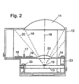
- Figure 2 shows the cross section of a motor vehicle radar system with a microwave antenna arrangement according to the invention according to an advantageous embodiment of the Invention, particularly those just described Dedicated to difficulties.
- the basic structure corresponds the radar system outlined in FIG. 1a, so that same reference numerals also designate the same elements.
- the advantageous embodiment of the invention is that the recess 15 in the component carrier 14 with a another antenna lens (sub lens) 22 is filled.
- the sub lens 22 could also be above or below the recess 15 can be mounted or it can instead of the lenticular dielectric body using a superstrate Find.
- there are different lens shapes or dielectric materials can be used.
- embodiments also fall under the Invention in which the "recess" of the component carrier 14 "so large” is that the component carrier shown here in one piece 14 consists of two separate parts, the both in the space between the focusing Means and the feed element are arranged and between which the electromagnetic waves can pass through.
Claims (8)
- Montage d'antenne hyperfréquence pour un système de radar de véhicule automobile comprenant :caractérisé en ce queau moins un moyen de focalisation (11) de préférence une lentille diélectrique,au moins un élément d'alimentation (10) qui reçoit et/ou émet des ondes électromagnétiques focalisées par le moyen de focalisation,un support de composant (14), monté dans la zone d'espace comprise entre le moyen de focalisation (11) et l'élément d'alimentation (10),le support d'éléments de construction est installé sensiblement transversale à la direction principale de rayonnement (18) du montage d'antenne,le support de composants (14) portant des composants électroniques ou électriques (16, 17) etle support de composants (14) étant écarté par rapport à l'élément d'alimentation (10) et par rapport au moyen de focalisation (11),le support de composants (14) comporte une découpe (15) pour le passage des ondes électromagnétiques, etles composants électroniques ou électriques (16, 17) sont prévus sur le support de composant (14) pour le traitement d'autres signaux que ceux émis ou reçus par l'élément d'alimentation (10).
- Montage d'antenne hyperfréquence selon la revendication 1,
caractérisé en ce que
le support de composants (14) et les composants électroniques ou électriques (16, 17) sont prévus pour le traitement de signaux situés dans une plage de fréquence inférieure à la plage de fréquence des ondes électromagnétiques. - Montage d'antenne hyperfréquence selon l'une quelconque des revendications 1 ou 2,
caractérisé en ce que
les composants électroniques ou électriques (16, 17) sont prévus principalement pour le traitement de signaux numériques. - Montage d'antenne hyperfréquence selon la revendication 1,
caractérisé en ce que
les composants électroniques ou électriques (16, 17) font partie d'un circuit d'alimentation en courant ou en tension. - Montage d'antenne hyperfréquence selon la revendication 1,
caractérisé par
au moins un autre moyen de focalisation (22) entre l'élément d'alimentation et le moyen de focalisation, cet autre moyen étant fixé au support de composants (14). - Montage d'antenne hyperfréquence selon la revendication 5,
caractérisé en ce que
l'autre moyen de focalisation est une lentille diélectrique (22) installée dans, sur, ou sous la découpe du support de composants. - Montage d'antenne hyperfréquence selon la revendication 5,
caractérisé en ce que
l'autre moyen de focalisation est un corps diélectrique dont les dimensions sont choisies pour fonctionner comme super couche pour les ondes électromagnétiques. - Application d'un dispositif d'antenne hyperfréquence selon l'une quelconque des revendications précédentes, à un système de radar de véhicule automobile.
Applications Claiming Priority (5)
| Application Number | Priority Date | Filing Date | Title |
|---|---|---|---|
| DE19704399 | 1997-02-06 | ||
| DE19704399 | 1997-02-06 | ||
| DE19755607A DE19755607A1 (de) | 1997-02-06 | 1997-12-15 | Mikrowellen-Antennenanordnung für ein Kraftfahrzeug-Radarsystem |
| DE19755607 | 1997-12-15 | ||
| PCT/DE1998/000343 WO1998035403A1 (fr) | 1997-02-06 | 1998-02-06 | Ensemble antenne hyperfrequence pour systeme radar de vehicule a moteur |
Publications (2)
| Publication Number | Publication Date |
|---|---|
| EP0896749A1 EP0896749A1 (fr) | 1999-02-17 |
| EP0896749B1 true EP0896749B1 (fr) | 2003-01-22 |
Family
ID=26033673
Family Applications (1)
| Application Number | Title | Priority Date | Filing Date |
|---|---|---|---|
| EP98909354A Expired - Lifetime EP0896749B1 (fr) | 1997-02-06 | 1998-02-06 | Ensemble antenne hyperfrequence pour systeme radar de vehicule a moteur |
Country Status (4)
| Country | Link |
|---|---|
| US (1) | US6075492A (fr) |
| EP (1) | EP0896749B1 (fr) |
| JP (1) | JP2000508874A (fr) |
| WO (1) | WO1998035403A1 (fr) |
Cited By (1)
| Publication number | Priority date | Publication date | Assignee | Title |
|---|---|---|---|---|
| EP4199261A1 (fr) * | 2021-12-14 | 2023-06-21 | Airbus SAS | Antenne ayant un élément de formation de rayonnement et aéronef comprenant une telle antenne |
Families Citing this family (30)
| Publication number | Priority date | Publication date | Assignee | Title |
|---|---|---|---|---|
| JP3186622B2 (ja) * | 1997-01-07 | 2001-07-11 | 株式会社村田製作所 | アンテナ装置および送受信装置 |
| DE19859002A1 (de) * | 1998-12-21 | 2000-06-29 | Bosch Gmbh Robert | Vorrichtung zum gerichteten Abstrahlen und/oder Aufnehmen elektromagnetischer Strahlung |
| CN1354900A (zh) * | 1999-02-12 | 2002-06-19 | Tdk株式会社 | 透镜天线及透镜天线阵列 |
| US6246381B1 (en) * | 1999-07-01 | 2001-06-12 | Telaxis Communications Corporation | Insert mold process for forming polarizing grid element |
| DE19939834A1 (de) * | 1999-08-21 | 2001-02-22 | Bosch Gmbh Robert | Mehrstrahliger Radarsensor mit einer Halterung für einen Fokussierkörper |
| DE19948025A1 (de) * | 1999-10-06 | 2001-04-12 | Bosch Gmbh Robert | Asymmetrischer, mehrstrahliger Radarsensor |
| EP1912080A3 (fr) * | 2000-08-16 | 2011-03-30 | Valeo Radar Systems, Inc. | Systèmes et techniques de radar automobiles |
| KR100767543B1 (ko) | 2000-08-16 | 2007-10-17 | 레이던 컴퍼니 | 스위치형 빔 안테나 구조 |
| EP1309882B1 (fr) * | 2000-08-16 | 2004-12-08 | Raytheon Company | Systeme de detection d'objets proches |
| US6577269B2 (en) | 2000-08-16 | 2003-06-10 | Raytheon Company | Radar detection method and apparatus |
| JP2004508627A (ja) | 2000-09-08 | 2004-03-18 | レイセオン・カンパニー | 経路予測システムおよび方法 |
| US6708100B2 (en) | 2001-03-14 | 2004-03-16 | Raytheon Company | Safe distance algorithm for adaptive cruise control |
| US6995730B2 (en) * | 2001-08-16 | 2006-02-07 | Raytheon Company | Antenna configurations for reduced radar complexity |
| US6556174B1 (en) * | 2001-12-05 | 2003-04-29 | Gary M. Hamman | Surveillance radar scanning antenna requiring no rotary joint |
| JP2003215233A (ja) | 2002-01-24 | 2003-07-30 | Murata Mfg Co Ltd | レーダヘッドモジュール |
| US6611227B1 (en) | 2002-08-08 | 2003-08-26 | Raytheon Company | Automotive side object detection sensor blockage detection system and related techniques |
| DE102004059332A1 (de) * | 2004-12-09 | 2006-06-14 | Robert Bosch Gmbh | Radar-Transceiver |
| EP1772748A1 (fr) * | 2005-10-05 | 2007-04-11 | Sony Deutschland GmbH | Appareil pour alignement des micro-ondes |
| EP2122599B1 (fr) | 2007-01-25 | 2019-11-13 | Magna Electronics Inc. | Système de détection de radar pour véhicule |
| KR101191293B1 (ko) * | 2008-03-31 | 2012-10-16 | 발레오 레이더 시스템즈, 인크. | 차량용 레이더 센서 방해 감지 장치 및 방법 |
| DE102012202913A1 (de) * | 2012-02-27 | 2013-08-29 | Robert Bosch Gmbh | Radarsensor |
| US9995822B2 (en) * | 2013-06-13 | 2018-06-12 | Continental Automotive Systems, Inc. | Integration of a radar sensor in a vehicle |
| DE102015015034B4 (de) * | 2015-11-23 | 2023-04-27 | Baumer Electric Ag | Sensoranordnung |
| WO2017180175A1 (fr) * | 2016-04-12 | 2017-10-19 | Archit Lens Technology Inc. | Système de lentille térahertz-gigahertz à grande ouverture |
| GB2575946B (en) * | 2017-06-07 | 2022-12-14 | Rogers Corp | Dielectric resonator antenna system |
| KR102529946B1 (ko) * | 2017-12-19 | 2023-05-08 | 삼성전자 주식회사 | 렌즈를 포함하는 빔포밍 안테나 모듈 |
| US11616302B2 (en) | 2018-01-15 | 2023-03-28 | Rogers Corporation | Dielectric resonator antenna having first and second dielectric portions |
| US11552390B2 (en) | 2018-09-11 | 2023-01-10 | Rogers Corporation | Dielectric resonator antenna system |
| CN113169455A (zh) | 2018-12-04 | 2021-07-23 | 罗杰斯公司 | 电介质电磁结构及其制造方法 |
| US11482790B2 (en) | 2020-04-08 | 2022-10-25 | Rogers Corporation | Dielectric lens and electromagnetic device with same |
Family Cites Families (10)
| Publication number | Priority date | Publication date | Assignee | Title |
|---|---|---|---|---|
| US4566321A (en) * | 1985-01-18 | 1986-01-28 | Transamerica Delaval Inc. | Microwave tank-contents level measuring assembly with lens-obturated wall-opening |
| EP0217426A3 (fr) * | 1985-08-08 | 1988-07-13 | The Secretary of State for Defence in Her Britannic Majesty's Government of the United Kingdom of Great Britain and | Dispositif d'antenne microbande |
| GB2252452B (en) * | 1985-09-05 | 1992-12-16 | Plessey Co Plc | Improvements in or relating to hybrid structures |
| GB9102585D0 (en) * | 1991-02-06 | 1991-03-27 | Marconi Gec Ltd | Radar system |
| US5264859A (en) * | 1991-11-05 | 1993-11-23 | Hughes Aircraft Company | Electronically scanned antenna for collision avoidance radar |
| US5455589A (en) * | 1994-01-07 | 1995-10-03 | Millitech Corporation | Compact microwave and millimeter wave radar |
| DE4412770A1 (de) * | 1994-04-13 | 1995-10-19 | Siemens Ag | Mikrowellen-Linsenantennenanordnung für Kraftfahrzeug-Abstandswarnradar |
| DE19511982A1 (de) * | 1995-03-31 | 1996-10-10 | Daimler Benz Ag | Anordnung für ein bildgebendes Radar |
| JP3042364B2 (ja) * | 1995-05-19 | 2000-05-15 | 株式会社村田製作所 | 誘電体アンテナ |
| DE19530065A1 (de) * | 1995-07-01 | 1997-01-09 | Bosch Gmbh Robert | Monostatischer FMCW-Radarsensor |
-
1998
- 1998-02-06 WO PCT/DE1998/000343 patent/WO1998035403A1/fr active IP Right Grant
- 1998-02-06 EP EP98909354A patent/EP0896749B1/fr not_active Expired - Lifetime
- 1998-02-06 US US09/155,829 patent/US6075492A/en not_active Expired - Lifetime
- 1998-02-06 JP JP10533565A patent/JP2000508874A/ja active Pending
Cited By (1)
| Publication number | Priority date | Publication date | Assignee | Title |
|---|---|---|---|---|
| EP4199261A1 (fr) * | 2021-12-14 | 2023-06-21 | Airbus SAS | Antenne ayant un élément de formation de rayonnement et aéronef comprenant une telle antenne |
Also Published As
| Publication number | Publication date |
|---|---|
| JP2000508874A (ja) | 2000-07-11 |
| EP0896749A1 (fr) | 1999-02-17 |
| US6075492A (en) | 2000-06-13 |
| WO1998035403A1 (fr) | 1998-08-13 |
Similar Documents
| Publication | Publication Date | Title |
|---|---|---|
| EP0896749B1 (fr) | Ensemble antenne hyperfrequence pour systeme radar de vehicule a moteur | |
| DE60103653T2 (de) | Verbesserung des erregers für sender/empfänger elektromagnetischer wellen in einer mehrreflektor-antenne | |
| DE19830811C2 (de) | Auf einem Kraftfahrzeug angebrachtes, mit elektromagnetischen Wellen arbeitendes Radargerät | |
| DE60113671T2 (de) | Sende-Empfangssatellitenantenne mit hoher Leistung und niedrigem Kostenaufwand | |
| DE19648203C2 (de) | Mehrstrahliges Kraftfahrzeug-Radarsystem | |
| DE69938413T2 (de) | Planare antenne und verfahren zur herstellung derselben | |
| DE4412770A1 (de) | Mikrowellen-Linsenantennenanordnung für Kraftfahrzeug-Abstandswarnradar | |
| DE4003057C2 (de) | Radarsensor zur Totwinkelüberwachung bei einem Kraftfahrzeug | |
| DE19859002A1 (de) | Vorrichtung zum gerichteten Abstrahlen und/oder Aufnehmen elektromagnetischer Strahlung | |
| DE3624897A1 (de) | Antennensystem | |
| DE2727883A1 (de) | Mikrowellen-antennensystem | |
| EP1245059A2 (fr) | Detecteur radar et antenne radar pour la surveillance de l'environnement d'un vehicule a moteur | |
| EP1754284A1 (fr) | Structure a guides d'ondes | |
| DE60107939T2 (de) | Reflektorantenne mit gemeinsamer apertur und verbessertem zuführungsentwurf | |
| DE102013206206A1 (de) | Substrat-integriertes Antennenmodul | |
| DE60315406T2 (de) | Hohlraumschlitzantenne | |
| EP3701280B1 (fr) | Capteur radar comportant une pluralité de directions de rayonnement principales | |
| DE112019005416T5 (de) | Antennensystem für ein Fahrzeug | |
| DE19951123C2 (de) | Radarsensor für ein Überwachen der Umgebung eines Kraftfahrzeuges | |
| DE102019123609A1 (de) | Antennenvorrichtung | |
| EP1476921B1 (fr) | Dispositif pour emettre et recevoir du rayonnement electromagnetique | |
| DE2925063C2 (de) | Radarantenne mit integrierter IFF-Antenne | |
| DE19719953B4 (de) | Kraftfahrzeug-Radarsensor | |
| WO2021032423A1 (fr) | Capteur radar, véhicule automobile et procédé de fonctionnement de capteur radar | |
| DE19755607A1 (de) | Mikrowellen-Antennenanordnung für ein Kraftfahrzeug-Radarsystem |
Legal Events
| Date | Code | Title | Description |
|---|---|---|---|
| PUAI | Public reference made under article 153(3) epc to a published international application that has entered the european phase |
Free format text: ORIGINAL CODE: 0009012 |
|
| AK | Designated contracting states |
Kind code of ref document: A1 Designated state(s): DE FR GB |
|
| 17P | Request for examination filed |
Effective date: 19990215 |
|
| GRAH | Despatch of communication of intention to grant a patent |
Free format text: ORIGINAL CODE: EPIDOS IGRA |
|
| GRAH | Despatch of communication of intention to grant a patent |
Free format text: ORIGINAL CODE: EPIDOS IGRA |
|
| GRAA | (expected) grant |
Free format text: ORIGINAL CODE: 0009210 |
|
| AK | Designated contracting states |
Kind code of ref document: B1 Designated state(s): DE FR GB |
|
| PG25 | Lapsed in a contracting state [announced via postgrant information from national office to epo] |
Ref country code: GB Free format text: LAPSE BECAUSE OF FAILURE TO SUBMIT A TRANSLATION OF THE DESCRIPTION OR TO PAY THE FEE WITHIN THE PRESCRIBED TIME-LIMIT Effective date: 20030122 |
|
| REG | Reference to a national code |
Ref country code: GB Ref legal event code: FG4D Free format text: NOT ENGLISH |
|
| REF | Corresponds to: |
Ref document number: 59806977 Country of ref document: DE Date of ref document: 20030227 Kind code of ref document: P |
|
| PGFP | Annual fee paid to national office [announced via postgrant information from national office to epo] |
Ref country code: GB Payment date: 20030428 Year of fee payment: 6 |
|
| GBV | Gb: ep patent (uk) treated as always having been void in accordance with gb section 77(7)/1977 [no translation filed] |
Effective date: 20030122 |
|
| ET | Fr: translation filed | ||
| PLBE | No opposition filed within time limit |
Free format text: ORIGINAL CODE: 0009261 |
|
| STAA | Information on the status of an ep patent application or granted ep patent |
Free format text: STATUS: NO OPPOSITION FILED WITHIN TIME LIMIT |
|
| 26N | No opposition filed |
Effective date: 20031023 |
|
| PGFP | Annual fee paid to national office [announced via postgrant information from national office to epo] |
Ref country code: DE Payment date: 20130426 Year of fee payment: 16 |
|
| PGFP | Annual fee paid to national office [announced via postgrant information from national office to epo] |
Ref country code: FR Payment date: 20140218 Year of fee payment: 17 |
|
| REG | Reference to a national code |
Ref country code: DE Ref legal event code: R119 Ref document number: 59806977 Country of ref document: DE |
|
| REG | Reference to a national code |
Ref country code: DE Ref legal event code: R119 Ref document number: 59806977 Country of ref document: DE Effective date: 20140902 |
|
| PG25 | Lapsed in a contracting state [announced via postgrant information from national office to epo] |
Ref country code: DE Free format text: LAPSE BECAUSE OF NON-PAYMENT OF DUE FEES Effective date: 20140902 |
|
| REG | Reference to a national code |
Ref country code: FR Ref legal event code: ST Effective date: 20151030 |
|
| PG25 | Lapsed in a contracting state [announced via postgrant information from national office to epo] |
Ref country code: FR Free format text: LAPSE BECAUSE OF NON-PAYMENT OF DUE FEES Effective date: 20150302 |