EP0896749B1 - Microwave antenna array for a motor vehicle radar system - Google Patents
Microwave antenna array for a motor vehicle radar system Download PDFInfo
- Publication number
- EP0896749B1 EP0896749B1 EP98909354A EP98909354A EP0896749B1 EP 0896749 B1 EP0896749 B1 EP 0896749B1 EP 98909354 A EP98909354 A EP 98909354A EP 98909354 A EP98909354 A EP 98909354A EP 0896749 B1 EP0896749 B1 EP 0896749B1
- Authority
- EP
- European Patent Office
- Prior art keywords
- antenna arrangement
- component carrier
- microwave antenna
- focusing means
- arrangement according
- Prior art date
- Legal status (The legal status is an assumption and is not a legal conclusion. Google has not performed a legal analysis and makes no representation as to the accuracy of the status listed.)
- Expired - Lifetime
Links
Images

Classifications
-
- H—ELECTRICITY
- H01—ELECTRIC ELEMENTS
- H01Q—ANTENNAS, i.e. RADIO AERIALS
- H01Q19/00—Combinations of primary active antenna elements and units with secondary devices, e.g. with quasi-optical devices, for giving the antenna a desired directional characteristic
- H01Q19/06—Combinations of primary active antenna elements and units with secondary devices, e.g. with quasi-optical devices, for giving the antenna a desired directional characteristic using refracting or diffracting devices, e.g. lens
- H01Q19/062—Combinations of primary active antenna elements and units with secondary devices, e.g. with quasi-optical devices, for giving the antenna a desired directional characteristic using refracting or diffracting devices, e.g. lens for focusing
-
- G—PHYSICS
- G01—MEASURING; TESTING
- G01S—RADIO DIRECTION-FINDING; RADIO NAVIGATION; DETERMINING DISTANCE OR VELOCITY BY USE OF RADIO WAVES; LOCATING OR PRESENCE-DETECTING BY USE OF THE REFLECTION OR RERADIATION OF RADIO WAVES; ANALOGOUS ARRANGEMENTS USING OTHER WAVES
- G01S13/00—Systems using the reflection or reradiation of radio waves, e.g. radar systems; Analogous systems using reflection or reradiation of waves whose nature or wavelength is irrelevant or unspecified
- G01S13/88—Radar or analogous systems specially adapted for specific applications
- G01S13/93—Radar or analogous systems specially adapted for specific applications for anti-collision purposes
- G01S13/931—Radar or analogous systems specially adapted for specific applications for anti-collision purposes of land vehicles
-
- G—PHYSICS
- G01—MEASURING; TESTING
- G01S—RADIO DIRECTION-FINDING; RADIO NAVIGATION; DETERMINING DISTANCE OR VELOCITY BY USE OF RADIO WAVES; LOCATING OR PRESENCE-DETECTING BY USE OF THE REFLECTION OR RERADIATION OF RADIO WAVES; ANALOGOUS ARRANGEMENTS USING OTHER WAVES
- G01S7/00—Details of systems according to groups G01S13/00, G01S15/00, G01S17/00
- G01S7/02—Details of systems according to groups G01S13/00, G01S15/00, G01S17/00 of systems according to group G01S13/00
- G01S7/03—Details of HF subsystems specially adapted therefor, e.g. common to transmitter and receiver
- G01S7/032—Constructional details for solid-state radar subsystems
-
- H—ELECTRICITY
- H01—ELECTRIC ELEMENTS
- H01Q—ANTENNAS, i.e. RADIO AERIALS
- H01Q1/00—Details of, or arrangements associated with, antennas
- H01Q1/27—Adaptation for use in or on movable bodies
- H01Q1/32—Adaptation for use in or on road or rail vehicles
- H01Q1/3208—Adaptation for use in or on road or rail vehicles characterised by the application wherein the antenna is used
- H01Q1/3233—Adaptation for use in or on road or rail vehicles characterised by the application wherein the antenna is used particular used as part of a sensor or in a security system, e.g. for automotive radar, navigation systems
-
- H—ELECTRICITY
- H01—ELECTRIC ELEMENTS
- H01Q—ANTENNAS, i.e. RADIO AERIALS
- H01Q15/00—Devices for reflection, refraction, diffraction or polarisation of waves radiated from an antenna, e.g. quasi-optical devices
- H01Q15/02—Refracting or diffracting devices, e.g. lens, prism
-
- H—ELECTRICITY
- H01—ELECTRIC ELEMENTS
- H01Q—ANTENNAS, i.e. RADIO AERIALS
- H01Q17/00—Devices for absorbing waves radiated from an antenna; Combinations of such devices with active antenna elements or systems
- H01Q17/001—Devices for absorbing waves radiated from an antenna; Combinations of such devices with active antenna elements or systems for modifying the directional characteristic of an aerial
-
- G—PHYSICS
- G01—MEASURING; TESTING
- G01S—RADIO DIRECTION-FINDING; RADIO NAVIGATION; DETERMINING DISTANCE OR VELOCITY BY USE OF RADIO WAVES; LOCATING OR PRESENCE-DETECTING BY USE OF THE REFLECTION OR RERADIATION OF RADIO WAVES; ANALOGOUS ARRANGEMENTS USING OTHER WAVES
- G01S13/00—Systems using the reflection or reradiation of radio waves, e.g. radar systems; Analogous systems using reflection or reradiation of waves whose nature or wavelength is irrelevant or unspecified
- G01S13/88—Radar or analogous systems specially adapted for specific applications
- G01S13/93—Radar or analogous systems specially adapted for specific applications for anti-collision purposes
- G01S13/931—Radar or analogous systems specially adapted for specific applications for anti-collision purposes of land vehicles
- G01S2013/9327—Sensor installation details
-
- G—PHYSICS
- G01—MEASURING; TESTING
- G01S—RADIO DIRECTION-FINDING; RADIO NAVIGATION; DETERMINING DISTANCE OR VELOCITY BY USE OF RADIO WAVES; LOCATING OR PRESENCE-DETECTING BY USE OF THE REFLECTION OR RERADIATION OF RADIO WAVES; ANALOGOUS ARRANGEMENTS USING OTHER WAVES
- G01S7/00—Details of systems according to groups G01S13/00, G01S15/00, G01S17/00
- G01S7/02—Details of systems according to groups G01S13/00, G01S15/00, G01S17/00 of systems according to group G01S13/00
- G01S7/03—Details of HF subsystems specially adapted therefor, e.g. common to transmitter and receiver
Definitions
- the present invention relates to a microwave antenna arrangement for a motor vehicle radar system.
- EP 498 524 A2 is a motor vehicle radar system known with two separate microwave antenna arrangements for the send and receive path. Both microwave antenna arrangements consist of one or more active Feeding elements and one dielectric lens each Focusing the radar beams. The whole arrangement is in a two-part housing, which in Radar system beam direction through the two dielectric lenses is completed.
- DE 44 12 770 A1 is a motor vehicle distance warning radar indicated that only a microwave lens antenna assembly for both the send and receive path needed.
- the radar system is in one Housing housed in the beam direction through the dielectric lens of the microwave antenna assembly completed becomes.
- a short focal length lens is used to reduce the lens thickness is also designed as a stepped lens is.
- US 5,455,589 is a compact micro and millimeter wave radar described, which is also for use in Motor vehicles is provided.
- This radar is going to to achieve a small size, an antenna arrangement used where the beam path of the electromagnetic Waves are optically "folded".
- an antenna arrangement consisting of a focusing lens and a Dining element with two reflective layers.
- a first layer called the transreflector, is in front or arranged behind the antenna lens. It leaves electromagnetic Waves of a certain direction of polarization through while doing electromagnetic waves of this perpendicular polarization direction is reflected.
- a second layer, called the twist reflector is about that Food element arranged. It reflects striking electromagnetic waves, being the waves in their Direction of polarization rotates by 90 °.
- This arrangement become radar beams both when transmitting and when Receive multiple times between the two layers mentioned reflected. Because of this, the distance between the Food elements and the antenna lens shortened to one size that is smaller than the focal length of the Antenna lens alone.
- DE 195 11 982 A1 describes an arrangement for an imaging Radar known with a transmitter and a receiver.
- waves are made a waveguide via a collimator lens through an antenna array are mapped onto a second lens.
- the antenna array thus receives the ones to be transmitted and the ones to be transmitted received waves and is between the semiconductor and the second lens arranged.
- the aim of this arrangement is not achieving a small size, but one Arrangement in which a local local oscillator is saved can be. It is very important with this arrangement that the antenna array and possibly also arranged on it Components for processing the to be sent and / or are provided for received signals. A downsizing the size of the radar is not given by this.
- the object of the present invention is a microwave antenna arrangement specify the size of a Transmitting and / or receiving system, which the antenna arrangement includes, in addition or as an alternative to known ones Constructions can be reduced.
- This task is accomplished by a microwave antenna arrangement according to the main claim solved, which is based on the teaching, component carrier, the part of the antenna arrangement itself have no function, nevertheless in a space between to arrange the feed element and the focusing means.
- Advantageous refinements of the invention result from the subordinate claims.
- microwave antenna arrangement is that the space available within a Housing in which the transmission and / or reception system is installed is optimally exploitable. Accordingly can the housing shifted by the invention spatial arrangement of other required modules, such as for example signal processing or power supply circuits, down to the immediately required size be reduced. It is particularly advantageous if the Component carrier arranged according to the invention and the components arranged for processing signals are provided that are in a frequency range that is lower than the frequency range of the electromagnetic Waves. This ensures good decoupling. If necessary, the components on the invention arranged component carrier with shielding plates be shielded. In the same sense, it is advantageous if the components for processing digital signals are provided or part of a power supply circuit are.
- the sub-lens is advantageous attached to the component carrier, whereby the assembly is much easier and less sensitive to tolerance than in known arrangements for reducing or preventing overexposure, such as in so-called Stick spotlights or polyrods.
- a dielectric body are, whose dimensions are chosen so that it for the used waves acts as a superstrate. Like these dimensions must be chosen, for example, in “Fundamental Superstrate (Cover) Effects on Printed Circuit Antennas "by Alexopoulos et. Al. In IEEE Transactions on Antennas and Propagation, vol. AP-32, no.8, page 807-816 described.
- FIG. 1a shows a motor vehicle radar system according to the invention with a corresponding microwave antenna arrangement in cross section.
- the antenna arrangement consisting of at least a feed element 10 and an antenna lens 11 housed in a housing 12.
- the antenna lens 11 part of the housing 12, i. it forms as it were a window for the sent or received Microwave radiation.
- the at least one feed element 10 is located on a first component carrier 13, the includes, for example, a microstrip circuit arrangement.
- the at least one feed element 10 is preferred a well known patch element. Alternatively, you can here instead of this first component carrier 13 and one or several patch elements 10, for example also one Waveguide arrangement are.
- Between the at least one Feeding element 10 and the antenna lens 11 is another Component carrier 14 arranged.
- Two dashed, V-shaped lines 19 and 20 characterize the optical paths of microwaves by way of example.
- 14 individual components are on the component carrier 16 and 17 outlined. These components are for Processing of signals other than the intended Signals received by the at least one feed element 10 or be delivered.
- the component carrier 14 preferably includes signal processing and signal evaluation circuits, those in the intermediate frequency range or Baseband carry out the evaluation of the received signals. Another example is current or voltage supply circuits called for the radar system.
- the component carriers 13 and 14 are in this embodiment on stamps 23 or on a housing projection 24 assembled. However, this excludes other mounting options not from.
- a spotlight is also an example (Polyrod) 21 above the feed element 10 outlined.
- a line 18 indicates the main beam direction the antenna arrangement.
- FIG. 1b shows the top view of the motor vehicle radar system described above according to the line of sight A-A.
- the component carrier 14 located above of the housing 12.
- the component carrier 14 already has the mentioned recess 15, which is preferably circular is designed and by the sent or received electromagnetic waves can pass through.
- the components 16 assumed as examples are outlined and 17 and the stamp 23 on which the component carrier 14 is mounted.
- a line 25 gives a symmetry or Center line of the component carrier 14.
- the motor vehicle radar system thus described with the inventive Microwave antenna arrangement reworks generally known radar methods, for example as FMCW radar or as a pulse radar.
- a microwave antenna arrangement of course all other microwave applications, for example Microwave, can be used.
- a known problem with generic antenna arrangements with at least one food element and one focusing Means is that due to a customary a small directivity of the food elements emitted microwave radiation at the focusing Means passing by. This in turn has two drawbacks Effects. On the one hand, this share will then of course not from the focusing means or the Antenna lens 11 focused in the desired direction, what the overall performance of the antenna arrangement deteriorates. On the other hand, this is the antenna lens 11 overexposing portion of the inner walls of the housing 12 reflected. This has the consequence that within the Housing 12 undesirably spreads microwave radiation, which may interfere with components 16 or 17 acts.
- the inner walls of the housing 12 with an absorbent To provide material. This way at least the disruptive effect of the radiating over the antenna lens 11 Microwaves can be reduced.
- an exact one is problematic Assembly of the Polyrods 21, especially when used as food elements 10 so-called patch antennas can be used.
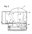
- Figure 2 shows the cross section of a motor vehicle radar system with a microwave antenna arrangement according to the invention according to an advantageous embodiment of the Invention, particularly those just described Dedicated to difficulties.
- the basic structure corresponds the radar system outlined in FIG. 1a, so that same reference numerals also designate the same elements.
- the advantageous embodiment of the invention is that the recess 15 in the component carrier 14 with a another antenna lens (sub lens) 22 is filled.
- the sub lens 22 could also be above or below the recess 15 can be mounted or it can instead of the lenticular dielectric body using a superstrate Find.
- there are different lens shapes or dielectric materials can be used.
- embodiments also fall under the Invention in which the "recess" of the component carrier 14 "so large” is that the component carrier shown here in one piece 14 consists of two separate parts, the both in the space between the focusing Means and the feed element are arranged and between which the electromagnetic waves can pass through.
Description
Die vorliegende Erfindung betrifft eine Mikrowellen-Antennenanordnung für ein Kraftfahrzeug-Radarsystem.The present invention relates to a microwave antenna arrangement for a motor vehicle radar system.
Aus zahlreichen Schriften ist mittlerweile bekannt, ein Kraftfahrzeug mit einem Radarsystem auszurüsten, welches beispielsweise zur Detektion von Hindernissen oder vorausfahrenden Fahrzeugen genutzt wird. Ein solches Radarsystem muß dabei an die besonderen Einbauumgebungen eines Kraftfahrzeugs angepaßt sein. Neben einer entsprechenden Resistenz gegenüber Temperaturschwankungen, Verschmutzungen oder Beschleunigungen spielt dabei auch die Baugröße des Radarsystems eine Rolle.Numerous writings have meanwhile known a To equip motor vehicles with a radar system, which for example for the detection of obstacles or those in front Vehicles is used. Such a radar system must be in the special installation environment of a motor vehicle be adjusted. In addition to a corresponding Resistance to temperature fluctuations, contamination or accelerations also play the size of the Radar systems matter.
Aus der EP 498 524 A2 ist ein Kraftfahrzeug-Radarsystem bekannt mit zwei getrennten Mikrowellen-Antennenanordnungen für den Sende- und für den Empfangsweg. Beide Mikrowellen-Antennenanordnungen bestehen aus einem oder mehreren aktiven Speiseelementen sowie je einer dielektrischen Linse zur Fokussierung der Radarstrahlen. Die gesamte Anordnung ist in einem zweigeteilten Gehäuse untergebracht, welches in Strahlrichtung des Radarsystems jeweils durch die beiden dielektrischen Linsen abgeschlossen ist.EP 498 524 A2 is a motor vehicle radar system known with two separate microwave antenna arrangements for the send and receive path. Both microwave antenna arrangements consist of one or more active Feeding elements and one dielectric lens each Focusing the radar beams. The whole arrangement is in a two-part housing, which in Radar system beam direction through the two dielectric lenses is completed.
In der DE 44 12 770 A1 ist ein Kraftfahrzeug-Abstandswarnradar angegeben, das nur eine Mikrowellen-Linsenantennenanordnung sowohl für den Sende- als auch für den Empfangsweg benötigt. Auch in diesem Fall ist das Radarsystem in einem Gehäuse untergebracht, das in Strahlrichtung durch die dielektrische Linse der Mikrowellen-Antennenanordnung abgeschlossen wird. Zur Erreichung einer geringen Bautiefe wird eine Linse mit kurzer Brennweite eingesetzt, die zur Verringerung der Linsendicke zudem als Stufenlinse ausgeführt ist.DE 44 12 770 A1 is a motor vehicle distance warning radar indicated that only a microwave lens antenna assembly for both the send and receive path needed. In this case too, the radar system is in one Housing housed in the beam direction through the dielectric lens of the microwave antenna assembly completed becomes. To achieve a shallow depth a short focal length lens is used to reduce the lens thickness is also designed as a stepped lens is.
In der US 5,455,589 ist ein kompaktes Mikro- und Millimeterwellenradar beschrieben, das ebenfalls für einen Einsatz in Kraftfahrzeugen vorgesehen ist. Bei diesem Radar wird, um eine geringe Baugröße zu erreichen, eine Antennenanordnung verwendet, bei der der Strahlengang der elektromagnetischen Wellen optisch "gefaltet" ist. Dazu ist eine Antennenanordnung, bestehend aus einer fokussierenden Linse und einem Speiseelement, mit zwei reflektierenden Schichten versehen. Eine erste, als Transreflektor bezeichnete Schicht, ist vor oder hinter der Antennenlinse angeordnet. Sie läßt elektromagnetische Wellen einer bestimmten Polarisationsrichtung durch, während sie elektromagnetische Wellen der dazu senkrecht stehenden Polarisationsrichtung reflektiert. Eine zweite, als Twistreflektor bezeichnete Schicht ist um das Speiseelement angeordnet. Sie reflektiert auftreffende elektromagnetische Wellen, wobei sie die Wellen in ihrer Polarisationsrichtung um 90° dreht. Durch diese Anordnung werden Radarstrahlen sowohl beim Senden als auch beim Empfangen mehrfach zwischen den beiden genannten Schichten reflektiert. Aus diesem Grund kann der Abstand zwischen den Speiseelementen und der Antennenlinse auf eine Größe verkürzt werden, die kleiner ist als die Brennweite der Antennenlinse allein.US 5,455,589 is a compact micro and millimeter wave radar described, which is also for use in Motor vehicles is provided. This radar is going to to achieve a small size, an antenna arrangement used where the beam path of the electromagnetic Waves are optically "folded". For this is an antenna arrangement, consisting of a focusing lens and a Dining element with two reflective layers. A first layer, called the transreflector, is in front or arranged behind the antenna lens. It leaves electromagnetic Waves of a certain direction of polarization through while doing electromagnetic waves of this perpendicular polarization direction is reflected. A second layer, called the twist reflector, is about that Food element arranged. It reflects striking electromagnetic waves, being the waves in their Direction of polarization rotates by 90 °. By this arrangement become radar beams both when transmitting and when Receive multiple times between the two layers mentioned reflected. Because of this, the distance between the Food elements and the antenna lens shortened to one size that is smaller than the focal length of the Antenna lens alone.
Wenn sich insbesondere auch die US 5,455,589 und die DE 44 12 770 dem Problem widmen, ein kompaktes Kraftfahrzeug-Radarsystem vorzuschlagen, vermeidet jedoch keine der genannten Lösungen den Nachteil, daß der Bereich zwischen den Speiseelementen und der Antennenlinse leer und damit weitgehend ungenutzt verbleibt. Die Größe dieses Bereichs wird durch die notwendige Brennweite der verwendeten Antennenlinse bestimmt. Bei allen beschriebenen Lösungen nimmt dieser Raum einen Großteil des insgesamt von dem Radarsystem benötigten Raumes ein.If in particular the US 5,455,589 and the DE 44 12 770 dedicate the problem to a compact motor vehicle radar system proposes, but does not avoid the solutions mentioned the disadvantage that the area between the food elements and the antenna lens empty and thus remains largely unused. The size of this area is used by the necessary focal length of the Antenna lens determined. With all the solutions described this space takes up a lot of the total of that Radar system required space.
Aus der DE 195 11 982 A1 ist eine Anordnung für ein bildgebendes Radar mit einem Sender und einem Empfänger bekannt. In einem Ausführungsbeispiel ist dargestellt, daß Wellen aus einem Hohlleiter über eine Kollimatorlinse durch ein Antennenarray hindurch auf eine zweite Linse abgebildet werden. Das Antennenarray erhält somit die zu sendenden und die zu empfangenen Wellen und ist zwischen dem Hohleiter und der zweiten Linse angeordnet. Ziel dieser Anordnung ist jedoch nicht die Erreichung einer geringen Baugröße, sondern eine Anordnung, bei der ein lokaler Empfangsoszillator eingespart werden kann. Ganz wesentlich ist bei dieser Anordnung, daß das Antennenarray und auch gegebenenfalls auf ihm angeordnete Bauelemente zur Verarbeitung der zu sendenden und/oder zu empfangenen Signale vorgesehen sind. Eine Verkleinerung der Baugröße des Radars ist hierdurch nicht gegeben. DE 195 11 982 A1 describes an arrangement for an imaging Radar known with a transmitter and a receiver. In one embodiment it is shown that waves are made a waveguide via a collimator lens through an antenna array are mapped onto a second lens. The antenna array thus receives the ones to be transmitted and the ones to be transmitted received waves and is between the semiconductor and the second lens arranged. However, the aim of this arrangement is not achieving a small size, but one Arrangement in which a local local oscillator is saved can be. It is very important with this arrangement that the antenna array and possibly also arranged on it Components for processing the to be sent and / or are provided for received signals. A downsizing the size of the radar is not given by this.
Aufgabe der vorliegenden Erfindung ist es, eine Mikrowellen-Antennenanordnung anzugeben, mit der die Baugröße eines Sende- und/oder Empfangsystems, welches die Antennenanordnung beinhaltet, ergänzend oder alternativ zu bekannten Konstruktionen verkleinerbar ist. Diese Aufgabe wird durch eine Mikrowellen-Antennenanordnung gemäß dem Hauptanspruch gelöst, dem als Grundgedanke die Lehre zugrunde liegt, Bauelementträger, die im Rahmen der Antennenanordnung selbst keine Funktion haben, trotzdem in einem Raumbereich zwischen dem Speiselement und dem fokussierenden Mittel anzuordnen. Vorteilhafte Ausgestaltungen der Erfindung ergeben sich aus den untergeordneten Ansprüchen.The object of the present invention is a microwave antenna arrangement specify the size of a Transmitting and / or receiving system, which the antenna arrangement includes, in addition or as an alternative to known ones Constructions can be reduced. This task is accomplished by a microwave antenna arrangement according to the main claim solved, which is based on the teaching, component carrier, the part of the antenna arrangement itself have no function, nevertheless in a space between to arrange the feed element and the focusing means. Advantageous refinements of the invention result from the subordinate claims.
Vorteil der erfindungsgemäßen Mikrowellen-Antennenanordnung ist, daß der zur Verfügung stehende Raum innerhalb eines Gehäuses, in das das Sende- und/oder Empfangsystems eingebaut ist, optimal ausgenutzt werden kann. Dementsprechend kann das Gehäuse durch die erfindungsgemäß verlagerte räumliche Anordnung von weiteren benötigten Baugruppen, wie zum Beispiel Signalverarbeitungs- oder Stromversorgungsschaltungen, bis auf die unmittelbar benötigte Größe reduziert werden. Besonders vorteilhaft ist es, wenn der erfindungsgemäß angeordnete Bauelementeträger und die auf ihm angeordneten Bauelemente zur Verarbeitung von Signalen vorgesehen sind, die in einem Frequenzbereich liegen, der niedriger ist als der Frequenzbereich der elektromagnetischen Wellen. Dies gewährleistet eine gute Entkopplung. Gegebenenfalls können die Bauelemente auf dem erfindungsgemäß angeordneten Bauelementeträger mit Abschirmblechen abgeschirmt sein. Im gleichen Sinne vorteilhaft ist es, wenn die Bauelemente zur Verarbeitung von digitalen Signalen vorgesehen sind oder Bestandteil einer Stromversorgungsschaltung sind.Advantage of the microwave antenna arrangement according to the invention is that the space available within a Housing in which the transmission and / or reception system is installed is optimally exploitable. Accordingly can the housing shifted by the invention spatial arrangement of other required modules, such as for example signal processing or power supply circuits, down to the immediately required size be reduced. It is particularly advantageous if the Component carrier arranged according to the invention and the components arranged for processing signals are provided that are in a frequency range that is lower than the frequency range of the electromagnetic Waves. This ensures good decoupling. If necessary, the components on the invention arranged component carrier with shielding plates be shielded. In the same sense, it is advantageous if the components for processing digital signals are provided or part of a power supply circuit are.
Wird entsprechend einer vorteilhaften Ausgestaltung der Erfindung als weiteres fokussierendes Mittel eine Sublinse verwendet, kann die Brennweite der Antennenanordnung und damit die Baugröße des Sende- und/oder Empfangsystems noch weiter verringert werden. Darüber hinaus besitzt eine solche Vorfokussierung den Vorteil, daß die Mikrowellen exakter auf die eigentliche (Haupt-)Antennenlinse fokussiert werden. Dadurch wird ein Überstrahlen dieser Antennenlinse (spillover loss) vermindert. Vorteilhafterweise ist die Sublinse an dem Bauelementträger befestigt, wodurch die Montage wesentlich einfacher und weniger toleranzempfindlich ist als bei bekannte Anordnungen zur Verringerung oder Verhinderung einer Überstrahlung, wie beispielsweise bei sogenannten Stielstrahlern oder Polyrods. Alternativ kann als vorfokussierendes Mittel auch ein dielektrischer Körper verwendet werden, dessen Abmessungen so gewählt sind, daß er für die verwendeten Wellen als Superstrate wirkt. Wie diese Abmessungen gewählt werden müssen, ist beispielsweise in "Fundamental Superstrate (Cover) Effects on Printed Circuit Antennas" von Alexopoulos et. al. in IEEE Transactions on Antennas and Propagation, vol. AP-32, no. 8, Seite 807-816 beschrieben.According to an advantageous embodiment of the Invention as a further focusing means a sub-lens used, the focal length of the antenna arrangement and so that the size of the transmitting and / or receiving system still can be further reduced. It also has one Pre-focusing has the advantage that the microwaves are more precise the actual (main) antenna lens can be focused. This will overexpose this antenna lens (spillover loss) decreased. The sub-lens is advantageous attached to the component carrier, whereby the assembly is much easier and less sensitive to tolerance than in known arrangements for reducing or preventing overexposure, such as in so-called Stick spotlights or polyrods. Alternatively, as a pre-focusing Means also used a dielectric body are, whose dimensions are chosen so that it for the used waves acts as a superstrate. Like these dimensions must be chosen, for example, in "Fundamental Superstrate (Cover) Effects on Printed Circuit Antennas "by Alexopoulos et. Al. In IEEE Transactions on Antennas and Propagation, vol. AP-32, no.8, page 807-816 described.
Nachfolgend werden Ausführungsbeispiele der Erfindung anhand
einer Zeichnung erläutert. Es zeigen
Figur 1a zeigt ein erfindungsgemäßes Kraftfahrzeug-Radarsystem
mit einer entsprechenden Mikrowellen-Antennenanordnung
im Querschnitt. Die Antennenanordnung, bestehend aus mindestens
einem Speiseelement 10 und einer Antennenlinse 11, ist
in einem Gehäuse 12 untergebracht. Dabei ist die Antennenlinse
11 Bestandteil des Gehäuses 12, d.h. sie bildet
gleichsam ein Fenster für die gesendete oder empfangene
Mikrowellenstrahlung. Das mindestens eine Speiseelement 10
befindet sich auf einem ersten Bauelementeträger 13, der
beispielsweise eine Microstrip-Schaltungsanordnung umfaßt.
Das mindestens eine Speiseelement 10 ist dabei vorzugsweise
ein hinreichend bekanntes Patchelement. Alternativ kann sich
hier anstelle dieses ersten Bauelementeträgers 13 und eines
oder mehrerer Patchelemente 10 beispielsweise auch eine
Hohlleiteranordnung befinden. Zwischen dem mindestens einen
Speiseelement 10 und der Antennenlinse 11 ist ein weiterer
Bauelementeträger 14 angeordnet. Dieser weist eine Aussparung
15 auf, durch die die von dem Speiseelement 10
gesendete oder empfangene Mikrowellenstrahlung hindurchtreten
kann. Zwei gestrichelte, V-förmige Linien 19 und 20
kennzeichnen beispielhaft Strahlengänge der Mikrowellen.
Desweiteren sind auf dem Bauelementeträger 14 einzelne Bauelemente
16 und 17 skizziert. Diese Bauelemente sind zur
Verarbeitung von anderen Signalen vorgesehen als den
Signalen, die von dem mindestens einen Speiselement 10 aufgenommen
oder abgegeben werden. Der Bauelementeträger 14
beinhaltet vorzugsweise Signalverarbeitungs- und Signalauswerteschaltungen,
die im Zwischenfrequenzbereich oder
Basisband die Auswertung der empfangenen Signale durchführen.
Als weiteres Beispiel seien Strom- oder Spannungsversorgungsschaltungen
für das Radarsystem genannt.FIG. 1a shows a motor vehicle radar system according to the invention
with a corresponding microwave antenna arrangement
in cross section. The antenna arrangement consisting of at least
a
Die Bauelementeträger 13 und 14 sind in diesem Ausführungsbeispiel
auf Stempeln 23 bzw. auf einem Gehäusevorsprung 24
montiert. Dies schließt jedoch andere Montagemöglichkeite
nicht aus. Außerdem ist ebenfalls beispielhaft ein Stielstrahler
(Polyrod) 21 oberhalb von dem Speiseelement 10
skizziert. Eine Linie 18 kennzeichnet die Hauptstrahlrichtung
der Antennenanordnung.The
Figur 1b zeigt die Draufsicht des zuvor beschriebenen Kraftfahrzeug-Radarsystems
gemäß der Ansichtslinie A-A. Zu sehen
ist der weiter oben liegende Bauelementeträger 14 innerhalb
des Gehäuses 12. Der Bauelementeträger 14 weist die bereits
genannte Aussparung 15 auf, die vorzugsweise kreisförmig
gestaltet ist und durch die gesendete oder empfangene
elektromagnetischen Wellen hindurchtreten können. Weiterhin
skizziert sind die beispielhaft angenommenen Bauelemente 16
und 17 sowie die Stempel 23, auf denen der Bauelementeträger
14 montiert ist. Eine Linie 25 gibt eine Symmetrie- oder
Mittellinie des Bauelementeträgers 14 an.FIG. 1b shows the top view of the motor vehicle radar system described above
according to the line of sight A-A. To see
is the
Das so beschriebene Kraftfahrzeug-Radarsystem mit der erfindungsgemäßen Mikrowellen-Antennenanordnung arbeitet nach allgemein bekannten Radarverfahren, beispielsweise als FMCW-Radar oder auch als Pulsradar. Darüber hinaus kann eine solche Mikrowellen-Antennenanordnung natürlich auch bei sämtlichen anderen Mikrowellenanwendungen, beispielsweise Richtfunk, verwendet werden. The motor vehicle radar system thus described with the inventive Microwave antenna arrangement reworks generally known radar methods, for example as FMCW radar or as a pulse radar. In addition, a such a microwave antenna arrangement of course all other microwave applications, for example Microwave, can be used.
Ein bekanntes Problem bei gattungsgemäßen Antennenanordnungen
mit mindestens einem Speiseelement und einem fokussierenden
Mittel ist, daß aufgrund einer üblicherweise
geringen eigenen Richtwirkung der Speiseelemente ein Anteil
abgegebener Mikrowellenstrahlung an dem fokussierenden
Mittel vorbeigeht. Dies wiederum hat zwei nachteilige
Wirkungen zur Folge. Zum einen wird dieser Anteil dann
natürlich nicht von dem fokussierenden Mittel bzw. der
Antennenlinse 11 in der gewünschten Richtung fokussiert, was
die Leistungsbilanz der Antennenanordnung insgesamt verschlechtert.
Zum anderen wird dieser, die Antennenlinse 11
überstrahlende Anteil von den Innenwänden des Gehäuses 12
reflektiert. Dies hat zur Folge, daß sich innerhalb des
Gehäuses 12 unerwünschterweise Mikrowellenstrahlung ausbreitet,
die möglicherweise störend auf die Bauelemente 16
oder 17 einwirkt. Zur Unterdrückung dieser Reflexionen ist
beispielsweise aus der genannten DE 44 12 770 A1 bekannt,
die Innenwände des Gehäuses 12 mit einem absorbierenden
Material zu versehen. Auf diese Weise kann zumindest die
störende Wirkung der die Antennenlinse 11 überstrahlenden
Mikrowellen verringert werden. Um darüber hinaus jedoch auch
die Leistungsbilanz der Antennenanordnung zu verbessern, ist
bekannt, die Speiseelemente 10 mit sogenannten Stielstrahlern
(Polyrods) 21 zu versehen, d.h. solche Stielstrahler
vor den Speiseelementen 10 anzuordnen. Ein Strahlengang
gesendeter Mikrowellen ohne Verwendung von Polyrods 21 ist
in Figur 1a mit der V-förmigen Linie 20, ein Strahlengang
mit Verwendung von Polyrods 21 ist mit der V-förmigen Linie
19 skizziert. Problematisch ist dabei jedoch eine exakte
Montage der Polyrods 21, insbesondere wenn als Speiseelemente
10 sogenannte Patchantennen verwendet werden.
Bereits eine geringe Schiefstellung der nur wenige Millimeter
großen Polyrods 21 führt wiederum zu einer Überstrahlung
der Antennenlinse 11. Auch müssen solche Polyrods 21
nur einige Mikrometer oberhalb von solchen Patchelementen
positioniert werden, was ebenfalls, insbesondere bei einer
Großserienfertigung problematisch ist.A known problem with generic antenna arrangements
with at least one food element and one focusing
Means is that due to a customary
a small directivity of the food elements
emitted microwave radiation at the focusing
Means passing by. This in turn has two drawbacks
Effects. On the one hand, this share will then
of course not from the focusing means or the
Figur 2 zeigt den Querschnitt eines Kraftfahrzeug-Radarsystems
mit einer erfindungsgemäßen Mikrowellen-Antennenanordnung
gemäß einer vorteilhaften Ausgestaltung der
Erfindung, die sich insbesondere den gerade geschilderten
Schwierigkeiten widmet. Der grundsätzliche Aufbau entspricht
dabei dem in Figur 1a skizzierten Radarsystem, so daß
gleiche Bezugszeichen auch gleiche Elemente bezeichnen. Die
vorteilhafte Ausgestaltung der Erfindung besteht darin, daß
die Aussparung 15 in dem Bauelementeträger 14 mit einer
weiteren Antennenlinse (Sublinse) 22 ausgefüllt ist. Alternativ
könnte die Sublinse 22 auch über oder unter der Aussparung
15 montiert sein oder es kann anstelle des linsenförmigen
dielektrischen Körpers ein Superstrate Verwendung
finden. Selbstverständlich sind verschiedene Linsenformen
oder dielektrischen Materialien verwendbar. Durch die fokussierende
Wirkung der Sublinse 22 werden eine Überstrahlung
der Antennenlinse 11 sowie die damit verbundenen, beschriebenen
Nachteile vermieden. Außerdem verkleinert sich durch
die Verwendung eines Mehrfach-Linsensystems die Brennweite
der gesamten Antennenanordnung, so daß auch aus diesem Grund
die Baugröße des Radarsystems noch weiter verkleinert werden
kann. Die Montage der Sublinse 22 ist dabei im Vergleich zu
der Montage von Polyrods 21 wesentlich weniger empfindlich
gegenüber Toleranzen. Selbstverständlich können jedoch, wenn
es einem Fachmann sinnvoll erscheint, zusätzlich noch Polyrods
21 verwendet werden.Figure 2 shows the cross section of a motor vehicle radar system
with a microwave antenna arrangement according to the invention
according to an advantageous embodiment of the
Invention, particularly those just described
Dedicated to difficulties. The basic structure corresponds
the radar system outlined in FIG. 1a, so that
same reference numerals also designate the same elements. The
advantageous embodiment of the invention is that
the
In Erweiterung oder Fortführung des bisher Beschriebenen
können natürlich auch mehrere Bauelementeträger 14 in dem
Bereich zwischen dem oder den Speiselementen 10 und dem
fokussierenden Mittel 11 angeordnet werden.In extension or continuation of what has been described so far
can of course also
Darüber hinaus fallen auch Ausführungsbeispiele unter die
Erfindung, bei denen die "Ausparung" des Bauelementeträgers
14 "so groß" ist, daß der hier einstückig dargestellte Bauelementeträger
14 aus zwei getrennten Teilen besteht, die
beide jeweils im Raumbereich zwischen dem fokussierenden
Mittel und dem Speiseelement angeordnet sind und zwischen
denen die elektromagnetischen Wellen hindurchtreten können.In addition, embodiments also fall under the
Invention in which the "recess" of the
Claims (8)
- Microwave antenna arrangement for a motor vehicle radar system,characterizedhaving at least one focusing means (11), preferably a dielectric lens,and at least one supply element (10) which picks up and/or outputs electromagnetic waves which are focused by the focusing means,a component carrier (14) being arranged in a space between the focusing means (11) and the at least one supply element (10),the component carrier being arranged approximately transverse to the main beam direction (18) of the antenna arrangement,electronic or electric components (16, 17) being arranged on the component (14), andthe component carrier (14) being spaced apart both from the at least one supply element (10) and from the focusing means (11),in that the component carrier (14) has a cut-out (15) for the passage of the electromagnetic waves, andin that the electronic or electric components (16, 17) on the component carrier (14) are provided for processing other signals than the signals which are picked up or output by the at least one supply element (10).
- Microwave antenna arrangement according to Claim 1, characterized in that the component carrier (14) and the electronic or electric components (16, 17) are provided for the purpose of processing signals which lie in a frequency range which is lower than the frequency range of the electromagnetic waves.
- Microwave antenna arrangement according to Claim 1 or 2, characterized in that the electronic or electric components (16, 17) are provided mainly for processing digital signals.
- Microwave antenna arrangement according to Claim 1, characterized in that the electronic or electric components (16, 17) are a constituent of a current or voltage supply circuit.
- Microwave antenna arrangement according to Claim 1, characterized in that arranged between the supply element and the focusing means is at least one further focusing means (22) which is fastened on the component carrier (14).
- Microwave antenna arrangement according to Claim 5, characterized in that the further focusing means is a dielectric lens (22) which is arranged in, above or below the cut-out in the component carrier.
- Microwave antenna arrangement according to Claim 5, characterized in that the further focusing means is a dielectric member whose dimensions are selected such that it acts as a superstrate for the electromagnetic waves.
- Use of a microwave antenna arrangement according to one of the preceding claims in a motor vehicle radar system.
Applications Claiming Priority (5)
| Application Number | Priority Date | Filing Date | Title |
|---|---|---|---|
| DE19704399 | 1997-02-06 | ||
| DE19704399 | 1997-02-06 | ||
| DE19755607A DE19755607A1 (en) | 1997-02-06 | 1997-12-15 | Microwave antenna arrangement for a motor vehicle radar system |
| DE19755607 | 1997-12-15 | ||
| PCT/DE1998/000343 WO1998035403A1 (en) | 1997-02-06 | 1998-02-06 | Microwave antenna array for a motor vehicle radar system |
Publications (2)
| Publication Number | Publication Date |
|---|---|
| EP0896749A1 EP0896749A1 (en) | 1999-02-17 |
| EP0896749B1 true EP0896749B1 (en) | 2003-01-22 |
Family
ID=26033673
Family Applications (1)
| Application Number | Title | Priority Date | Filing Date |
|---|---|---|---|
| EP98909354A Expired - Lifetime EP0896749B1 (en) | 1997-02-06 | 1998-02-06 | Microwave antenna array for a motor vehicle radar system |
Country Status (4)
| Country | Link |
|---|---|
| US (1) | US6075492A (en) |
| EP (1) | EP0896749B1 (en) |
| JP (1) | JP2000508874A (en) |
| WO (1) | WO1998035403A1 (en) |
Cited By (1)
| Publication number | Priority date | Publication date | Assignee | Title |
|---|---|---|---|---|
| EP4199261A1 (en) * | 2021-12-14 | 2023-06-21 | Airbus SAS | Antenna with a radiation forming element and aircraft comprising such antenna |
Families Citing this family (30)
| Publication number | Priority date | Publication date | Assignee | Title |
|---|---|---|---|---|
| JP3186622B2 (en) * | 1997-01-07 | 2001-07-11 | 株式会社村田製作所 | Antenna device and transmitting / receiving device |
| DE19859002A1 (en) * | 1998-12-21 | 2000-06-29 | Bosch Gmbh Robert | Arrangement for positioning elements for transmitting or receiving electromagnetic emissions for radar system of motor vehicle |
| EP1152486A4 (en) * | 1999-02-12 | 2006-02-15 | Tdk Corp | Lens antenna and lens antenna array |
| US6246381B1 (en) * | 1999-07-01 | 2001-06-12 | Telaxis Communications Corporation | Insert mold process for forming polarizing grid element |
| DE19939834A1 (en) | 1999-08-21 | 2001-02-22 | Bosch Gmbh Robert | Multi-beam radar sensor e.g. automobile obstacle sensor, has focusing body supported by holder relative to each transmission/reception element and common dielectric lens in path of each beam |
| DE19948025A1 (en) * | 1999-10-06 | 2001-04-12 | Bosch Gmbh Robert | Asymmetric, multi-beam radar sensor |
| JP5063851B2 (en) * | 2000-08-16 | 2012-10-31 | ヴァレオ・レイダー・システムズ・インコーポレーテッド | Proximity object detection system |
| US6707419B2 (en) | 2000-08-16 | 2004-03-16 | Raytheon Company | Radar transmitter circuitry and techniques |
| WO2002015334A1 (en) | 2000-08-16 | 2002-02-21 | Raytheon Company | Switched beam antenna architecture |
| WO2002014891A2 (en) * | 2000-08-16 | 2002-02-21 | Raytheon Company | Automotive radar systems and techniques |
| WO2002021156A2 (en) | 2000-09-08 | 2002-03-14 | Raytheon Company | Path prediction system and method |
| US6708100B2 (en) | 2001-03-14 | 2004-03-16 | Raytheon Company | Safe distance algorithm for adaptive cruise control |
| US6995730B2 (en) * | 2001-08-16 | 2006-02-07 | Raytheon Company | Antenna configurations for reduced radar complexity |
| US6556174B1 (en) * | 2001-12-05 | 2003-04-29 | Gary M. Hamman | Surveillance radar scanning antenna requiring no rotary joint |
| JP2003215233A (en) * | 2002-01-24 | 2003-07-30 | Murata Mfg Co Ltd | Radar head module |
| US6611227B1 (en) | 2002-08-08 | 2003-08-26 | Raytheon Company | Automotive side object detection sensor blockage detection system and related techniques |
| DE102004059332A1 (en) * | 2004-12-09 | 2006-06-14 | Robert Bosch Gmbh | Radar transceiver |
| EP1772748A1 (en) * | 2005-10-05 | 2007-04-11 | Sony Deutschland GmbH | Microwave alignment apparatus |
| US8013780B2 (en) | 2007-01-25 | 2011-09-06 | Magna Electronics Inc. | Radar sensing system for vehicle |
| JP5653901B2 (en) * | 2008-03-31 | 2015-01-14 | ヴァレオ・レイダー・システムズ・インコーポレーテッド | Automotive radar sensor blockage detection device |
| DE102012202913A1 (en) * | 2012-02-27 | 2013-08-29 | Robert Bosch Gmbh | radar sensor |
| US9995822B2 (en) * | 2013-06-13 | 2018-06-12 | Continental Automotive Systems, Inc. | Integration of a radar sensor in a vehicle |
| DE102015015034B4 (en) * | 2015-11-23 | 2023-04-27 | Baumer Electric Ag | sensor arrangement |
| CN109891216A (en) * | 2016-04-12 | 2019-06-14 | 镜元科技股份有限公司 | Large aperture Terahertz-girz lens systems |
| KR102312067B1 (en) * | 2017-06-07 | 2021-10-13 | 로저스코포레이션 | Dielectric Resonator Antenna System |
| KR102529946B1 (en) * | 2017-12-19 | 2023-05-08 | 삼성전자 주식회사 | Beam forming antenna module including lens |
| US11616302B2 (en) | 2018-01-15 | 2023-03-28 | Rogers Corporation | Dielectric resonator antenna having first and second dielectric portions |
| US11552390B2 (en) | 2018-09-11 | 2023-01-10 | Rogers Corporation | Dielectric resonator antenna system |
| US11637377B2 (en) | 2018-12-04 | 2023-04-25 | Rogers Corporation | Dielectric electromagnetic structure and method of making the same |
| US11482790B2 (en) | 2020-04-08 | 2022-10-25 | Rogers Corporation | Dielectric lens and electromagnetic device with same |
Family Cites Families (10)
| Publication number | Priority date | Publication date | Assignee | Title |
|---|---|---|---|---|
| US4566321A (en) * | 1985-01-18 | 1986-01-28 | Transamerica Delaval Inc. | Microwave tank-contents level measuring assembly with lens-obturated wall-opening |
| EP0217426A3 (en) * | 1985-08-08 | 1988-07-13 | The Secretary of State for Defence in Her Britannic Majesty's Government of the United Kingdom of Great Britain and | Microstrip antenna device |
| GB2252452B (en) * | 1985-09-05 | 1992-12-16 | Plessey Co Plc | Improvements in or relating to hybrid structures |
| GB9102585D0 (en) * | 1991-02-06 | 1991-03-27 | Marconi Gec Ltd | Radar system |
| US5264859A (en) * | 1991-11-05 | 1993-11-23 | Hughes Aircraft Company | Electronically scanned antenna for collision avoidance radar |
| US5455589A (en) * | 1994-01-07 | 1995-10-03 | Millitech Corporation | Compact microwave and millimeter wave radar |
| DE4412770A1 (en) * | 1994-04-13 | 1995-10-19 | Siemens Ag | Microwave lens aerial for car distance warning radar |
| DE19511982A1 (en) * | 1995-03-31 | 1996-10-10 | Daimler Benz Ag | Image generating radar system |
| JP3042364B2 (en) * | 1995-05-19 | 2000-05-15 | 株式会社村田製作所 | Dielectric antenna |
| DE19530065A1 (en) * | 1995-07-01 | 1997-01-09 | Bosch Gmbh Robert | Monostatic FMCW radar sensor |
-
1998
- 1998-02-06 WO PCT/DE1998/000343 patent/WO1998035403A1/en active IP Right Grant
- 1998-02-06 EP EP98909354A patent/EP0896749B1/en not_active Expired - Lifetime
- 1998-02-06 US US09/155,829 patent/US6075492A/en not_active Expired - Lifetime
- 1998-02-06 JP JP10533565A patent/JP2000508874A/en active Pending
Cited By (1)
| Publication number | Priority date | Publication date | Assignee | Title |
|---|---|---|---|---|
| EP4199261A1 (en) * | 2021-12-14 | 2023-06-21 | Airbus SAS | Antenna with a radiation forming element and aircraft comprising such antenna |
Also Published As
| Publication number | Publication date |
|---|---|
| EP0896749A1 (en) | 1999-02-17 |
| JP2000508874A (en) | 2000-07-11 |
| WO1998035403A1 (en) | 1998-08-13 |
| US6075492A (en) | 2000-06-13 |
Similar Documents
| Publication | Publication Date | Title |
|---|---|---|
| EP0896749B1 (en) | Microwave antenna array for a motor vehicle radar system | |
| DE60103653T2 (en) | IMPROVEMENT OF THE ENTRY FOR TRANSMITTERS / RECEIVERS ELECTROMAGNETIC WAVES IN A MULTILREFLECTOR ANTENNA | |
| DE19830811C2 (en) | Radar device mounted on a motor vehicle and operating with electromagnetic waves | |
| DE60113671T2 (en) | High-power and low-cost transceiver satellite antenna | |
| DE19648203C2 (en) | Multi-beam automotive radar system | |
| DE69938413T2 (en) | PLANAR ANTENNA AND METHOD FOR THE PRODUCTION THEREOF | |
| DE4412770A1 (en) | Microwave lens aerial for car distance warning radar | |
| DE4003057C2 (en) | Radar sensor for blind spot monitoring in a motor vehicle | |
| DE19859002A1 (en) | Arrangement for positioning elements for transmitting or receiving electromagnetic emissions for radar system of motor vehicle | |
| DE3624897A1 (en) | ANTENNA SYSTEM | |
| EP1245059A2 (en) | Radar sensor and radar antenna for monitoring the environment of a motor vehicle | |
| WO2005099042A1 (en) | Waveguide structure | |
| DE60107939T2 (en) | REFLECTOR ANTENNA WITH COMMON APERTURE AND IMPROVED FEEDING DRAFT | |
| DE102013206206A1 (en) | Substrate-integrated antenna module | |
| DE60315406T2 (en) | Cavity slot antenna | |
| EP3701280B1 (en) | Radar sensor having a plurality of main beam directions | |
| DE112019005416T5 (en) | Antenna system for a vehicle | |
| DE19951123C2 (en) | Radar sensor for monitoring the surroundings of a motor vehicle | |
| DE102019123609A1 (en) | ANTENNA DEVICE | |
| EP1476921B1 (en) | Device for emitting and receiving electromagnetic radiation | |
| DE2925063C2 (en) | Radar antenna with integrated IFF antenna | |
| DE19719953B4 (en) | Automotive radar sensor | |
| WO2021032423A1 (en) | Radar sensor, motor vehicle, and method for operating a radar sensor | |
| DE19755607A1 (en) | Microwave antenna arrangement for a motor vehicle radar system | |
| DE3644891A1 (en) | RECEIVER FOR MICROWAVES AND MILLIMETER WAVES |
Legal Events
| Date | Code | Title | Description |
|---|---|---|---|
| PUAI | Public reference made under article 153(3) epc to a published international application that has entered the european phase |
Free format text: ORIGINAL CODE: 0009012 |
|
| AK | Designated contracting states |
Kind code of ref document: A1 Designated state(s): DE FR GB |
|
| 17P | Request for examination filed |
Effective date: 19990215 |
|
| GRAH | Despatch of communication of intention to grant a patent |
Free format text: ORIGINAL CODE: EPIDOS IGRA |
|
| GRAH | Despatch of communication of intention to grant a patent |
Free format text: ORIGINAL CODE: EPIDOS IGRA |
|
| GRAA | (expected) grant |
Free format text: ORIGINAL CODE: 0009210 |
|
| AK | Designated contracting states |
Kind code of ref document: B1 Designated state(s): DE FR GB |
|
| PG25 | Lapsed in a contracting state [announced via postgrant information from national office to epo] |
Ref country code: GB Free format text: LAPSE BECAUSE OF FAILURE TO SUBMIT A TRANSLATION OF THE DESCRIPTION OR TO PAY THE FEE WITHIN THE PRESCRIBED TIME-LIMIT Effective date: 20030122 |
|
| REG | Reference to a national code |
Ref country code: GB Ref legal event code: FG4D Free format text: NOT ENGLISH |
|
| REF | Corresponds to: |
Ref document number: 59806977 Country of ref document: DE Date of ref document: 20030227 Kind code of ref document: P |
|
| PGFP | Annual fee paid to national office [announced via postgrant information from national office to epo] |
Ref country code: GB Payment date: 20030428 Year of fee payment: 6 |
|
| GBV | Gb: ep patent (uk) treated as always having been void in accordance with gb section 77(7)/1977 [no translation filed] |
Effective date: 20030122 |
|
| ET | Fr: translation filed | ||
| PLBE | No opposition filed within time limit |
Free format text: ORIGINAL CODE: 0009261 |
|
| STAA | Information on the status of an ep patent application or granted ep patent |
Free format text: STATUS: NO OPPOSITION FILED WITHIN TIME LIMIT |
|
| 26N | No opposition filed |
Effective date: 20031023 |
|
| PGFP | Annual fee paid to national office [announced via postgrant information from national office to epo] |
Ref country code: DE Payment date: 20130426 Year of fee payment: 16 |
|
| PGFP | Annual fee paid to national office [announced via postgrant information from national office to epo] |
Ref country code: FR Payment date: 20140218 Year of fee payment: 17 |
|
| REG | Reference to a national code |
Ref country code: DE Ref legal event code: R119 Ref document number: 59806977 Country of ref document: DE |
|
| REG | Reference to a national code |
Ref country code: DE Ref legal event code: R119 Ref document number: 59806977 Country of ref document: DE Effective date: 20140902 |
|
| PG25 | Lapsed in a contracting state [announced via postgrant information from national office to epo] |
Ref country code: DE Free format text: LAPSE BECAUSE OF NON-PAYMENT OF DUE FEES Effective date: 20140902 |
|
| REG | Reference to a national code |
Ref country code: FR Ref legal event code: ST Effective date: 20151030 |
|
| PG25 | Lapsed in a contracting state [announced via postgrant information from national office to epo] |
Ref country code: FR Free format text: LAPSE BECAUSE OF NON-PAYMENT OF DUE FEES Effective date: 20150302 |