EP0895570B1 - Gaine textile de ventilation et hotte a flux laminaire - Google Patents
Gaine textile de ventilation et hotte a flux laminaire Download PDFInfo
- Publication number
- EP0895570B1 EP0895570B1 EP97918187A EP97918187A EP0895570B1 EP 0895570 B1 EP0895570 B1 EP 0895570B1 EP 97918187 A EP97918187 A EP 97918187A EP 97918187 A EP97918187 A EP 97918187A EP 0895570 B1 EP0895570 B1 EP 0895570B1
- Authority
- EP
- European Patent Office
- Prior art keywords
- sheath
- air
- diffusion
- porous
- sterile
- Prior art date
- Legal status (The legal status is an assumption and is not a legal conclusion. Google has not performed a legal analysis and makes no representation as to the accuracy of the status listed.)
- Expired - Lifetime
Links
- 239000004744 fabric Substances 0.000 title claims abstract description 11
- 238000009423 ventilation Methods 0.000 title 1
- 238000009792 diffusion process Methods 0.000 claims abstract description 38
- 230000004224 protection Effects 0.000 claims abstract description 21
- 239000004753 textile Substances 0.000 claims description 17
- 239000003570 air Substances 0.000 description 46
- 210000003462 vein Anatomy 0.000 description 8
- 239000002245 particle Substances 0.000 description 4
- 239000012080 ambient air Substances 0.000 description 2
- 238000011109 contamination Methods 0.000 description 2
- 239000000428 dust Substances 0.000 description 2
- 239000000835 fiber Substances 0.000 description 2
- 238000012423 maintenance Methods 0.000 description 2
- 239000004033 plastic Substances 0.000 description 2
- 239000002985 plastic film Substances 0.000 description 2
- 229920006255 plastic film Polymers 0.000 description 2
- 229920000728 polyester Polymers 0.000 description 2
- 230000001105 regulatory effect Effects 0.000 description 2
- 239000000725 suspension Substances 0.000 description 2
- 230000006399 behavior Effects 0.000 description 1
- 239000003795 chemical substances by application Substances 0.000 description 1
- 230000000694 effects Effects 0.000 description 1
- 230000036512 infertility Effects 0.000 description 1
- 238000009434 installation Methods 0.000 description 1
- 239000000463 material Substances 0.000 description 1
- 238000005259 measurement Methods 0.000 description 1
- 238000011045 prefiltration Methods 0.000 description 1
- 229910001220 stainless steel Inorganic materials 0.000 description 1
- 239000010935 stainless steel Substances 0.000 description 1
- 238000004804 winding Methods 0.000 description 1
Images
Classifications
-
- F—MECHANICAL ENGINEERING; LIGHTING; HEATING; WEAPONS; BLASTING
- F24—HEATING; RANGES; VENTILATING
- F24F—AIR-CONDITIONING; AIR-HUMIDIFICATION; VENTILATION; USE OF AIR CURRENTS FOR SCREENING
- F24F9/00—Use of air currents for screening, e.g. air curtains
-
- F—MECHANICAL ENGINEERING; LIGHTING; HEATING; WEAPONS; BLASTING
- F24—HEATING; RANGES; VENTILATING
- F24F—AIR-CONDITIONING; AIR-HUMIDIFICATION; VENTILATION; USE OF AIR CURRENTS FOR SCREENING
- F24F3/00—Air-conditioning systems in which conditioned primary air is supplied from one or more central stations to distributing units in the rooms or spaces where it may receive secondary treatment; Apparatus specially designed for such systems
- F24F3/12—Air-conditioning systems in which conditioned primary air is supplied from one or more central stations to distributing units in the rooms or spaces where it may receive secondary treatment; Apparatus specially designed for such systems characterised by the treatment of the air otherwise than by heating and cooling
- F24F3/16—Air-conditioning systems in which conditioned primary air is supplied from one or more central stations to distributing units in the rooms or spaces where it may receive secondary treatment; Apparatus specially designed for such systems characterised by the treatment of the air otherwise than by heating and cooling by purification, e.g. by filtering; by sterilisation; by ozonisation
- F24F3/163—Clean air work stations, i.e. selected areas within a space which filtered air is passed
-
- F—MECHANICAL ENGINEERING; LIGHTING; HEATING; WEAPONS; BLASTING
- F24—HEATING; RANGES; VENTILATING
- F24F—AIR-CONDITIONING; AIR-HUMIDIFICATION; VENTILATION; USE OF AIR CURRENTS FOR SCREENING
- F24F13/00—Details common to, or for air-conditioning, air-humidification, ventilation or use of air currents for screening
- F24F13/02—Ducting arrangements
- F24F13/06—Outlets for directing or distributing air into rooms or spaces, e.g. ceiling air diffuser
- F24F2013/0608—Perforated ducts
-
- Y—GENERAL TAGGING OF NEW TECHNOLOGICAL DEVELOPMENTS; GENERAL TAGGING OF CROSS-SECTIONAL TECHNOLOGIES SPANNING OVER SEVERAL SECTIONS OF THE IPC; TECHNICAL SUBJECTS COVERED BY FORMER USPC CROSS-REFERENCE ART COLLECTIONS [XRACs] AND DIGESTS
- Y02—TECHNOLOGIES OR APPLICATIONS FOR MITIGATION OR ADAPTATION AGAINST CLIMATE CHANGE
- Y02A—TECHNOLOGIES FOR ADAPTATION TO CLIMATE CHANGE
- Y02A50/00—TECHNOLOGIES FOR ADAPTATION TO CLIMATE CHANGE in human health protection, e.g. against extreme weather
- Y02A50/20—Air quality improvement or preservation, e.g. vehicle emission control or emission reduction by using catalytic converters
Definitions
- the present invention relates generally to protection close to a work station located in a contaminated atmosphere, and more particularly a device for close product protection sensitive to contamination by contaminating agents carried by the atmosphere, said products being positioned on a work surface.
- the present invention relates more particularly to a sheath for close protection of conveying sensitive products by diffusion of a sterile air stream, especially in one direction substantially vertical, formed of a sealed wall and a porous wall extending longitudinally along the axis of the sheath, said sheath defining a sterile air supply duct.
- the invention also relates to a laminar flow hood, washable or disposable, as well as a device for close protection of a Large width work surface comprising such sheaths.
- the present invention proposes devices for close protection using one or more textile sheath (s) capable (s) of generating the desired gas flows. It is a priori possible to make such a device using a textile sheath comprising a part diffusing median bordered longitudinally on each side by two slits.
- the Applicant has found that such a sheath of perimeter 1.885 m, consisting for example of a median porous part corresponding to 25% of the perimeter (i.e. 0.47 m) bordered by two slots each 15 mm wide (i.e. 0.016% of the perimeter for the two slots), if it allows to obtain certain interesting results, however does not allow to obtain optimum results. Indeed, the respective velocities of the veins fast and slow air is not constant along the duct.
- One of the objects of the present invention is to solve the aforementioned problems and relates to a sheath enabling the diffusion of a sterile air stream at low median speed and lateral speed higher.
- sheath textile a pipe having any section and a portion of which important is made of textile.
- the sheath according to the invention may include plastic parts, especially semi-rigid parts.
- the present invention relates to a sheath for protection closer to conveying sensitive products by diffusion of a vein sterile air according to claim 1.
- the width of the veins is in total substantially equal to the diameter of the sheath, the rapid jets being substantially tangent to the ends of the diameter and directed like the slow jets perpendicularly said diameter.
- the median or slow diffusion speed is between 0.2 and 1 m / s and the speed of the lateral or rapid jets is between 0.5 and 5 m / s for an air pressure in the duct included between 25 and 1000 Pa.
- Wall porous preferably occupies between 25 to 50% of the perimeter of the sheath.
- the outer wall of the diffusion bag has two watertight side bands integral with the edges of said watertight wall and a porous central zone bordered by two lateral slits adjacent to said side bands.
- the ratio between the porous middle zone and a slot is between 10 and 100.
- the resistance to the passage of air from the wall porous is high enough to achieve good consistency longitudinal air velocities passing through it to feed the bag of diffusion.
- the invention also relates to a textile sheath according to claim 6.
- skirts can be of equal length.
- the sheath can also be used for constitute a means of protection of a limited volume. Indeed, if the sheath thus formed is limited at the ends by a plane perpendicular to the axis of the textile sheath, a classic laminar flow hood is thus obtained the main part is washable.
- the invention also provides a device for protection close to a large work plan, which has above of said work plan a plurality of sheaths juxtaposed in a direction parallel to the direction of the transverse edge of said work plane, each sheath being formed by an upper sealed half-sheath and a half-sheath porous bottom defining a sterile air supply duct, the outer longitudinal end, located at a longitudinal edge of the worktop, of the upper sealed half-sheath of each of the sheaths located at both ends of the juxtaposition, being extended tangentially by a skirt.
- the device according to the invention makes it possible to protect from Large work surfaces, with a median sterile air stream at slow diffusion laterally bordered by sterile diffusion veins of air higher, the diffusion of sterile air taking place in one direction substantially perpendicular to the work plane.
- Such a device has a much lower installation cost, about six times lower than that of conventional boxed devices.
- the textile sheath device according to the invention can be advantageously cleaned by simple disassembly of the sheaths because the sterile air supply of said ducts can be placed so deported from them. Dismantling the sheaths does not imply then necessarily disassembly of the power supply.
- the device classic which includes an air supply fan surmounted by a prefilter and fitted at the outlet with a terminal filter, is therefore non-removable.
- the textile sheath device according to the invention makes it possible to completely advantageous way of distributing above the worktop of sterile air at regulated temperature and hydrometry.
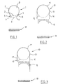
- Figure 1 is a cross-sectional view of a first variant according to the invention
- the figure is a cross-sectional view of a second variant according to the invention.
- Figure 3 is a cross-sectional view of a third variant according to the invention.
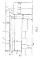
- Figure 4 is a schematic side view of a mode of realization of a device with several sheaths according to the invention.
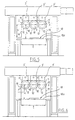
- Figure 5 is a schematic front view of the device of the figure 4.
- Figure 6 is a schematic front view of a variant of realization of the device with several sheaths according to the invention.
- a textile sheath 1 enclosing a conduit 9 supplied with sterile air has a waterproof wall 2 made of "waterproof textile or in plastic film "forming part of the perimeter and a porous wall 3 through which a longitudinal pocket of diffusion 4, the external wall 5 of which comprises two lateral bands 6 integral longitudinal ends of the sealed wall 2 and a middle zone 8 porous bordered by two side slots 7 adjacent to said side strips 6 waterproof.
- the sheath is located above a conveyor 18.
- the diffusion pocket thus created removes the constraint of the longitudinal distribution.
- the porous part 3 occupies 25% or 0.47 m of arc.
- the slots have a width of 5 to 10 mm and the porous median zone 8 has a width 300 mm.
- the device thus produced ensures slow diffusion by through the middle zone, this diffusion being framed by two fast jets.
- a sheath 10 is formed of a lower porous half-sheath 12.
- the perimeter is also 1.885 m.
- the longitudinal edges 13 of the sealed half-sheath 11 are each extended tangentially by a skirt 14, the two skirts being equal length.
- the porous fabric In the absence of a slit, the porous fabric can be chosen fairly resistant to the passage of air to obtain a good distribution longitudinal.
- Skirts can be made of plastic film, each weighted by a stainless steel rod placed in a hem at the bottom (not shown).
- the scale of speeds that generally achieves the device according to the invention is included for the middle zone (slow) between 0.2 and 1 m / s and for fast jets between 0.5 and 5 m / s for air pressure between 25 and 1000 Pa.
- the useful width 1 of the work surface 18 is approximately equal to 1.20 m.
- This device comprises above said work surface 18, a plurality of textile sheaths 10 juxtaposed contiguously according to a direction X parallel to the direction of the transverse edge 18a of said plane of work 18.
- a direction X parallel to the direction of the transverse edge 18a of said plane of work 18.
- Each sheath 10 is formed by an upper sealed half-sheath 11 and a lower porous half-sheath 12 which delimit a conduit sterile air supply 9 of tubular shape and longitudinal axis X '.
- the fabric used to make the upper waterproof half-sheath is for example a polyester fiber fabric which has a porosity of 5 to 10 ⁇ m of mesh openings.
- the fabric used for the porous half-sheath lower is for example a polyester fiber fabric which has a porosity of 15 to 30 ⁇ m of mesh openings.
- the sheaths 10 extend longitudinally parallel to the edge longitudinal 18b of said work plane, over the entire length thereof (here 3.50m).
- the end longitudinal external, located at a longitudinal edge 18b of the plane of work 18, of the upper sealed half-sheath 11 of each of the sheaths 10 located at the two ends of the juxtaposition, is extended tangentially by a skirt 14.
- the two skirts 14 located at each end of the juxtaposition extend substantially perpendicularly to work plan 18.
- the two skirts 14 have lengths equal, here the length h 'of said skirts 14 corresponds substantially to the height h, taken perpendicular to the work surface, existing between the work plane 18 and the median axis X of the ducts 10.
- skirts have different lengths, here the skirt 16 is shorter than the skirt 17 and extends over a length h "substantially equal to 50% of said height h existing between work plan 18 and axis X of ducts 10.
- the length of the skirts can be between 50% and 100% of the existing height between the work surface and the center line sheaths.
- skirts are preferably made of plastic transparent so that an operator located on one side of the device can visually check what is happening on the work surface.
- a skirt 16 has a length h "less than the existing height between the center line of the ducts and the work surface, allows advantageously for an operator to intervene manually on the plane of work 18.
- the sheaths are suspended from 2 'structure tubes of the device by means of suspension struts 3 ', here three suspension struts 3' distributed regularly over the entire length of the sheaths 10.
- the sheaths 10 are supplied by a 1 "supply device via 1 'supply ducts in sterile air, the air pressure prevailing in each duct 9 of each sheath being between 25 and 1000 Pa.
- the profile of the speeds of the sterile air coming from the device shown in Figures 4 to 6, is such that it has a median speed of relatively slow sterile air diffusion between 0.2 and 1m / s and a higher sterile air diffusion speed between 0.5 and 5 m / s.
- flexible ceiling can be provided porous (here not shown) stretched just below the sheaths over the entire width of the worktop. This is particularly advantageous for mitigate slight increases in air diffusion rate at the junction of two successive sheaths and obtain in the middle part of the plan working a profile of flat diffusion speeds.
- Such a flexible stretch ceiling can be advantageously used in an embodiment in which the two transverse end sides of said device are closed by skirts of the type located on the edges longitudinal end sheaths, to limit edge effects transverse and reduce pressure losses.
- the use of such a ceiling flexible porous stretched below said sheaths allows better control sterile air flows from them.
- Air quality is therefore class 100 according to the American standard FS 209E.
- the particle measurement of the ambient air in the room in which said work plan is located leads to a classification of ambient air in Class 100,000 according to said standard FS 209E with a number greater than 1000 of large particles contaminating with cubic foot.
Landscapes
- Engineering & Computer Science (AREA)
- Chemical & Material Sciences (AREA)
- Combustion & Propulsion (AREA)
- Mechanical Engineering (AREA)
- General Engineering & Computer Science (AREA)
- Respiratory Apparatuses And Protective Means (AREA)
- Professional, Industrial, Or Sporting Protective Garments (AREA)
- Duct Arrangements (AREA)
- Outer Garments And Coats (AREA)
- Treatment Of Fiber Materials (AREA)
- Preliminary Treatment Of Fibers (AREA)
- Prevention Of Fouling (AREA)
- Separation Using Semi-Permeable Membranes (AREA)
- Helmets And Other Head Coverings (AREA)
- Accommodation For Nursing Or Treatment Tables (AREA)
- Ventilation (AREA)
Description
Claims (17)
- Gaine textile (1) pour la protection rapprochée du convoyage de produits sensibles par diffusion d'une veine d'air stérile, notamment selon une direction sensiblement verticale, formée d'une paroi étanche supérieure (2) et d'une paroi poreuse inférieure (3) s'étendant selon l'axe X longitudinal de la gaine et délimitant entre elles un conduit (9) d'alimentation d'air stérile, caractérisée en ce qu'elle comporte une poche de diffusion (4) s'étendant longitudinalement, reliée par l'intermédiaire de la paroi poreuse (3) au conduit (9) de la gaine, véhiculant l'air stérile et fermée par une paroi externe (5) poreuse par laquelle diffuse la veine d'air stérile, de manière à assurer une diffusion médiane d'air stérile à vitesse lente et, de part et d'autre, une diffusion latérale d'air stérile à vitesse plus élevée.
- Gaine selon la revendication 1, caractérisée en ce que la paroi externe (5) de la poche de diffusion (4) comporte deux bandes latérales étanches (6) solidaires des bords de la paroi étanche (2) et une zone médiane (8) poreuse bordée de deux fentes latérales (7) adjacentes auxdites bandes latérales.
- Gaine selon la revendication 1 ou 2, caractérisée en ce que la résistance au passage de l'air de la paroi poreuse est suffisamment élevée pour obtenir une bonne constance longitudinale des vitesses d'air la traversant.
- Gaine selon l'une des revendications 1 à 3, caractérisée en ce que la paroi poreuse (3) occupe de 25 % à 50 % du périmètre de la gaine.
- Gaine selon l'une des revendications 1 à 4, caractérisée en ce que le rapport entre la largeur de la zone médiane poreuse et une fente est compris entre 10 et 100.
- Gaine textile (10) pour la protection rapprochée du convoyage de produits sensibles par diffusion d'une veine d'air stérile, notamment selon une direction sensiblement verticale, formée d'une paroi étanche supérieure et d'une paroi poreuse inférieure, s'étendant selon l'axe longitudinal de la gaine et délimitant entre elles un conduit d'alimentation d'air stérile, caractérisée en ce qu'elle est formée d'une demi-gaine étanche (11) supérieure et d'une demi-gaine poreuse (12) inférieure assurant une diffusion médiane d'air stérile à vitesse lente, les extrémités (13) longitudinales de la demi-gaine étanche (12) étant prolongées chacune tangentiellement par une jupe (14) assurant de part et d'autre de la diffusion médiane d'air stérile à vitesse lente, une diffusion latérale d'air stérile à vitesse plus élevée.
- Gaine selon la revendication 6, caractérisée en ce que les jupes sont de longueur égale.
- Gaine selon la revendication 6, caractérisée en ce que les jupes (16, 17) sont de longueur différente.
- Gaine selon l'une des revendications 1 à 8, caractérisée en ce que la vitesse de diffusion médiane est comprise entre 0,2 et 1 m/s et la vitesse de diffusion latérale est comprise entre 0,5 et 5 m/s pour une pression d'air dans le conduit comprise entre 25 et 1000 Pa.
- Hotte à flux laminaire, notamment en tissu, caractérisée en ce qu'elle est formée d'une gaine selon l'une des revendications 6 à 8 et en ce qu'elle est fermée aux deux extrémités par un plan perpendiculaire à l'axe de la gaine textile.
- Dispositif pour la protection rapprochée d'un plan de travail (18) de grande largeur, caractérisé en ce qu'il comporte au-dessus dudit plan de travail (18), une pluralité de gaines (10), juxtaposées suivant une direction parallèle à la direction du bord transversal (18a) dudit plan de travail (18), chaque gaine (10) étant formée d'une demi-gaine étanche supérieure (11) et d'une demi-gaine poreuse inférieure (12) , délimitant un conduit (9) d'alimentation d'air stérile, l'extrémité longitudinale externe (11a), située au niveau d'un bord longitudinal (18b) du plan de travail (18), de la demi-gaine étanche supérieure (11) de chacune des gaines (10) situées aux deux extrémités de la juxtaposition, étant prolongée tangentiellement par une jupe (14).
- Dispositif selon la revendication 11, caractérisé en ce que les gaines (10) sont jointives.
- Dispositif selon l'une des revendications 11 ou 12, caractérisé en ce qu'il présente une vitesse médiane lente de diffusion d'air stérile comprise entre 0,2 et 1 m/s et une vitesse latérale rapide de diffusion d'air stérile comprise entre 0,5 et 5 m/s pour une pression d'air dans chaque conduit comprise entre 25 et 1000 Pa.
- Dispositif selon l'une des revendications 11 à 13, caractérisé en ce que les jupes (14) sont de longueur égale.
- Dispositif selon l'une des revendications 11 à 13, caractérisé en ce que les jupes (16, 17) sont de longueur différente.
- Dispositif selon l'une des revendications 14 ou 15, caractérisé en ce que la longueur des jupes (14, 16, 17) est comprise entre 50 % et 100 % de la hauteur existante entre le plan de travail (18) et l'axe médian (X) des gaines (10).
- Dispositif selon l'une des revendications 11 à 16, caractérisé en ce qu'il est prévu un plafond souple poreux tendu juste en dessous des gaines sur toute la largeur du plan de travail.
Applications Claiming Priority (3)
| Application Number | Priority Date | Filing Date | Title |
|---|---|---|---|
| FR9605234A FR2748048B1 (fr) | 1996-04-25 | 1996-04-25 | Gaine textile pour la protection rapprochee du convoyage de produits sensibles et hotte a flux laminaire comportant une telle gaine |
| FR9605234 | 1996-04-25 | ||
| PCT/FR1997/000626 WO1997040325A1 (fr) | 1996-04-25 | 1997-04-09 | Gaine textile de ventilation et hotte a flux laminaire |
Publications (2)
| Publication Number | Publication Date |
|---|---|
| EP0895570A1 EP0895570A1 (fr) | 1999-02-10 |
| EP0895570B1 true EP0895570B1 (fr) | 2000-01-12 |
Family
ID=9491584
Family Applications (1)
| Application Number | Title | Priority Date | Filing Date |
|---|---|---|---|
| EP97918187A Expired - Lifetime EP0895570B1 (fr) | 1996-04-25 | 1997-04-09 | Gaine textile de ventilation et hotte a flux laminaire |
Country Status (13)
| Country | Link |
|---|---|
| US (1) | US6113486A (fr) |
| EP (1) | EP0895570B1 (fr) |
| JP (1) | JP3651906B2 (fr) |
| CN (1) | CN1114071C (fr) |
| AT (1) | ATE188768T1 (fr) |
| CA (1) | CA2252937C (fr) |
| DE (1) | DE69701138T2 (fr) |
| DK (1) | DK0895570T3 (fr) |
| ES (1) | ES2141611T3 (fr) |
| FR (1) | FR2748048B1 (fr) |
| GR (1) | GR3033101T3 (fr) |
| PT (1) | PT895570E (fr) |
| WO (1) | WO1997040325A1 (fr) |
Families Citing this family (24)
| Publication number | Priority date | Publication date | Assignee | Title |
|---|---|---|---|---|
| FR2787558B1 (fr) * | 1998-12-18 | 2001-03-09 | U N I R Ultra Propre Nutrition | Dispositif de diffusion d'air sterile dans une gaine textile assurant la protection rapprochee de produits sensibles |
| FR2788843B1 (fr) | 1999-01-26 | 2001-04-13 | U N I R Ultra Propre Nutrition | Dispositif de protection rapprochee de produits sensibles par diffusion d'air sterile, avec des extremites d'interface protegees |
| AU770154B2 (en) * | 1999-03-03 | 2004-02-12 | Barcol-Air Ag | Air cooling element, method for operating the same, and an air cooling arrangement |
| GB2352799B (en) * | 1999-08-06 | 2004-03-10 | Abb Steward Ltd | Apparatus for providing conditioning medium in a space |
| FR2824626B1 (fr) * | 2001-05-14 | 2004-04-16 | Pierre Bridenne | Procede et dispositif pour diffuser un flux de protection a l'egard d'une ambiance environnante |
| US6626754B2 (en) * | 2001-07-27 | 2003-09-30 | Rite-Hite Holding Corporation | Conical air filter |
| US6565430B2 (en) * | 2001-09-13 | 2003-05-20 | Rite-Hite Holding Corporation | Pliable air duct with dust and condensation repellency |
| US7037188B2 (en) * | 2003-04-08 | 2006-05-02 | Halo Innovations, Inc. | Systems for delivering conditioned air to personal breathing zones |
| FR2865406B1 (fr) * | 2004-01-22 | 2007-11-30 | Acanthe | Diffuseur a effet parietal |
| DE102004009709B4 (de) * | 2004-02-27 | 2009-06-25 | Cognis Ip Management Gmbh | Verfahren zum Pastillieren von schmelzbarem Produkt |
| JP4767005B2 (ja) * | 2005-12-08 | 2011-09-07 | 株式会社大気社 | 空調設備 |
| US20080176506A1 (en) * | 2007-01-22 | 2008-07-24 | Rite-Hite Holding Corporation | Fabric diffuser with programmed airflow |
| JP5356797B2 (ja) * | 2007-12-21 | 2013-12-04 | 旭化成ホームズ株式会社 | 空気吹き出し部の構造 |
| JP5356796B2 (ja) * | 2008-02-08 | 2013-12-04 | 旭化成ホームズ株式会社 | 空気吹き出し部の構造 |
| US9039503B2 (en) * | 2008-02-29 | 2015-05-26 | Rite-Hite Holding Corporation | Longitudinally split fabric air duct |
| JP5484515B2 (ja) | 2011-07-08 | 2014-05-07 | 興研株式会社 | 局所空気清浄化装置 |
| JP5484421B2 (ja) | 2011-07-29 | 2014-05-07 | 興研株式会社 | 局所空気清浄化装置 |
| JP5484516B2 (ja) | 2011-10-03 | 2014-05-07 | 興研株式会社 | 清浄空気吹出装置 |
| JP2013088012A (ja) * | 2011-10-17 | 2013-05-13 | Koken Ltd | 局所空気清浄化装置 |
| DE202011052210U1 (de) | 2011-12-06 | 2012-12-19 | M. Schall Gmbh + Co. Kg. | Belüftungsvorrichtung für Reinräume sowie Reinraum mit einer solchen Vorrichtung |
| US9901011B2 (en) | 2015-11-04 | 2018-02-20 | Rite-Hite Holding Corporation | Cooling systems for devices arranged in rows |
| US10251312B2 (en) | 2016-09-09 | 2019-04-02 | Rite-Hite Holding Corporation | Cooling systems for devices arranged in rows |
| DE102017127476A1 (de) * | 2017-11-21 | 2019-05-23 | Airbus Operations Gmbh | Membran zum Anbringen an ein Rohr um einen luftführenden Raum zu erhalten |
| WO2020072691A2 (fr) | 2018-10-02 | 2020-04-09 | Rite-Hite Holding Corporation | Systèmes de barrière à l'air pour confinement de zone de centre de données |
Family Cites Families (18)
| Publication number | Priority date | Publication date | Assignee | Title |
|---|---|---|---|---|
| GB1317833A (en) * | 1968-05-02 | 1973-05-23 | Howorth & Co Ltd James | Operating theatres |
| US3719136A (en) * | 1970-09-21 | 1973-03-06 | Nat Defence | Method and means for providing a clean area |
| CA936740A (en) * | 1971-06-18 | 1973-11-13 | Powlesland Engineering Limited | Device for producing dynamic flow in fluids to form curtains of the fluid |
| US3776121A (en) * | 1972-06-23 | 1973-12-04 | A Truhan | Controlled environmental apparatus for industry |
| GB1488513A (en) * | 1974-04-26 | 1977-10-12 | Howorth Air Eng Ltd | Clean air zone |
| IN152016B (fr) * | 1980-11-24 | 1983-09-24 | Klenzaids Engineers Plc | |
| JPS633143A (ja) * | 1986-06-21 | 1988-01-08 | Chizuko Ozawa | 漏風ダクト |
| DE3729952A1 (de) * | 1987-03-12 | 1988-09-22 | Alex Mueller | Lastkraftwagen oder -anhaenger mit einem durch ein kuehlaggregat am vorderende durch luftumwaelzung gekuehlten laderaum |
| DE3711613A1 (de) * | 1987-04-07 | 1988-10-27 | Luwa Ag | Reinraumsystem |
| JPH01144908A (ja) * | 1987-11-30 | 1989-06-07 | Chizuko Ozawa | 漏風ダクト |
| DE3909497A1 (de) * | 1989-03-22 | 1990-10-04 | Jean Braun | Temperierte luftverteilung |
| JPH0345852A (ja) * | 1989-07-12 | 1991-02-27 | Mitsubishi Rayon Eng Co Ltd | 気体吹き出しダクト部材 |
| JPH03110343A (ja) * | 1989-09-20 | 1991-05-10 | Mitsubishi Rayon Eng Co Ltd | 気体吹き出しダクト部材 |
| JPH03110342A (ja) * | 1989-09-20 | 1991-05-10 | Mitsubishi Rayon Eng Co Ltd | 気体吹き出しダクト |
| JPH0694295A (ja) * | 1992-09-10 | 1994-04-05 | Taikisha Ltd | ダクト装置 |
| US5655963A (en) * | 1995-12-04 | 1997-08-12 | Rite-Hite Corporation | Air-releasing endcap for fabric air dispersion system |
| US5769708A (en) * | 1996-10-22 | 1998-06-23 | Rite-Hite Corporation | Fabric air dispersion system with air dispersing panels |
| US6565430B2 (en) * | 2001-09-13 | 2003-05-20 | Rite-Hite Holding Corporation | Pliable air duct with dust and condensation repellency |
-
1996
- 1996-04-25 FR FR9605234A patent/FR2748048B1/fr not_active Expired - Fee Related
-
1997
- 1997-04-09 WO PCT/FR1997/000626 patent/WO1997040325A1/fr not_active Ceased
- 1997-04-09 DE DE69701138T patent/DE69701138T2/de not_active Expired - Fee Related
- 1997-04-09 JP JP53776997A patent/JP3651906B2/ja not_active Expired - Fee Related
- 1997-04-09 ES ES97918187T patent/ES2141611T3/es not_active Expired - Lifetime
- 1997-04-09 DK DK97918187T patent/DK0895570T3/da active
- 1997-04-09 AT AT97918187T patent/ATE188768T1/de not_active IP Right Cessation
- 1997-04-09 US US09/171,775 patent/US6113486A/en not_active Expired - Fee Related
- 1997-04-09 CN CN97195362A patent/CN1114071C/zh not_active Expired - Fee Related
- 1997-04-09 EP EP97918187A patent/EP0895570B1/fr not_active Expired - Lifetime
- 1997-04-09 CA CA002252937A patent/CA2252937C/fr not_active Expired - Fee Related
- 1997-04-09 PT PT97918187T patent/PT895570E/pt unknown
-
2000
- 2000-03-29 GR GR20000400790T patent/GR3033101T3/el not_active IP Right Cessation
Also Published As
| Publication number | Publication date |
|---|---|
| CA2252937C (fr) | 2005-06-07 |
| WO1997040325A1 (fr) | 1997-10-30 |
| CN1221484A (zh) | 1999-06-30 |
| JP3651906B2 (ja) | 2005-05-25 |
| CA2252937A1 (fr) | 1997-10-30 |
| EP0895570A1 (fr) | 1999-02-10 |
| ES2141611T3 (es) | 2000-03-16 |
| DE69701138T2 (de) | 2000-06-21 |
| FR2748048A1 (fr) | 1997-10-31 |
| GR3033101T3 (en) | 2000-08-31 |
| FR2748048B1 (fr) | 1998-07-31 |
| PT895570E (pt) | 2000-06-30 |
| DK0895570T3 (da) | 2000-05-08 |
| CN1114071C (zh) | 2003-07-09 |
| ATE188768T1 (de) | 2000-01-15 |
| DE69701138D1 (de) | 2000-02-17 |
| JP2000508757A (ja) | 2000-07-11 |
| US6113486A (en) | 2000-09-05 |
Similar Documents
| Publication | Publication Date | Title |
|---|---|---|
| CA2252937C (fr) | Gaine textile de ventilation et hotte a flux laminaire | |
| CA2447086C (fr) | Procede et dispositif pour diffuser un flux de protection a l'egard d'une ambiance environnante | |
| CA2259455C (fr) | Procede et dispositif de protection d'un plan de travail | |
| EP3103741B1 (fr) | Installation de traitement d'une bande convoyeuse de produits agroalimentaires | |
| EP0099818B1 (fr) | Procédé de confinement de la pollution d'un local à l'aide d'une veine gazeuse | |
| FR2808458A1 (fr) | Dispositif de filtration rotatif en continu d'un liquide tel qu'une solution contenant un precipite | |
| WO1991005210A1 (fr) | Procede et dispositif pour maintenir une atmosphere propre a temperature regulee sur un poste de travail | |
| EP0270653A1 (fr) | Dispositif pour nettoyer et/ou decontaminer en continu une bande d'un film en matiere thermoplastique. | |
| FR2748508A1 (fr) | Gaine textile pour la protection rapprochee du convoyage de produits sensibles et hotte a flux laminaire comportant une telle gaine | |
| EP1147345B1 (fr) | Dispositif de diffusion d'air sterile | |
| CA2218416C (fr) | Dispositif de protection anti-contamination rapprochee | |
| EP0787950A1 (fr) | Salle à empoussièrement contrÔlé | |
| EP1141636B1 (fr) | Dispositif de diffusion d'air sterile dans une gaine textile | |
| US20230392867A1 (en) | Document remediation system | |
| FR2622960A1 (fr) | Unite de production de flux laminaire sterile a circulation verticale | |
| FR2821834A1 (fr) | Procede et convoyeur pour le transport d'articles legers sous l'action de jets d'air, avec mise en oeuvre d'un flux d'air de protection des articles contre la contamination | |
| FR2692028A1 (fr) | Système d'alimentation en air d'un plénum d'une installation de ventilation. | |
| FR2785040A1 (fr) | Dispositif et procede pour la protection rapprochee de produits ou objets sensibles a des agents contaminants vehicules par l'air ambiant | |
| KR100472268B1 (ko) | 환기용섬유외피및층류후드 | |
| FR2758180A1 (fr) | Installation de ventilation a flux laminaire unidirectionnel | |
| FR2664526A1 (fr) | Systeme de manutention de tranche a protection contre les poussieres. | |
| FR2740205A1 (fr) | Dispositif de protection contre l'aerocontamination | |
| FR3008169A1 (fr) | Dispositif de traitement de l'air d'une zone confinee et procede de regulation du flux d'air dans ladite zone confinee |
Legal Events
| Date | Code | Title | Description |
|---|---|---|---|
| PUAI | Public reference made under article 153(3) epc to a published international application that has entered the european phase |
Free format text: ORIGINAL CODE: 0009012 |
|
| 17P | Request for examination filed |
Effective date: 19981116 |
|
| AK | Designated contracting states |
Kind code of ref document: A1 Designated state(s): AT BE CH DE DK ES FI FR GB GR IE IT LI LU MC NL PT SE |
|
| GRAG | Despatch of communication of intention to grant |
Free format text: ORIGINAL CODE: EPIDOS AGRA |
|
| 17Q | First examination report despatched |
Effective date: 19990226 |
|
| GRAG | Despatch of communication of intention to grant |
Free format text: ORIGINAL CODE: EPIDOS AGRA |
|
| GRAH | Despatch of communication of intention to grant a patent |
Free format text: ORIGINAL CODE: EPIDOS IGRA |
|
| GRAH | Despatch of communication of intention to grant a patent |
Free format text: ORIGINAL CODE: EPIDOS IGRA |
|
| GRAA | (expected) grant |
Free format text: ORIGINAL CODE: 0009210 |
|
| AK | Designated contracting states |
Kind code of ref document: B1 Designated state(s): AT BE CH DE DK ES FI FR GB GR IE IT LI LU MC NL PT SE |
|
| REF | Corresponds to: |
Ref document number: 188768 Country of ref document: AT Date of ref document: 20000115 Kind code of ref document: T |
|
| ITF | It: translation for a ep patent filed | ||
| REG | Reference to a national code |
Ref country code: CH Ref legal event code: NV Representative=s name: MICHELI & CIE INGENIEURS-CONSEILS Ref country code: CH Ref legal event code: EP |
|
| GBT | Gb: translation of ep patent filed (gb section 77(6)(a)/1977) |
Effective date: 20000112 |
|
| REF | Corresponds to: |
Ref document number: 69701138 Country of ref document: DE Date of ref document: 20000217 |
|
| REG | Reference to a national code |
Ref country code: IE Ref legal event code: FG4D Free format text: FRENCH |
|
| REG | Reference to a national code |
Ref country code: ES Ref legal event code: FG2A Ref document number: 2141611 Country of ref document: ES Kind code of ref document: T3 |
|
| REG | Reference to a national code |
Ref country code: DK Ref legal event code: T3 |
|
| REG | Reference to a national code |
Ref country code: PT Ref legal event code: SC4A Free format text: AVAILABILITY OF NATIONAL TRANSLATION Effective date: 20000323 |
|
| PG25 | Lapsed in a contracting state [announced via postgrant information from national office to epo] |
Ref country code: MC Free format text: LAPSE BECAUSE OF NON-PAYMENT OF DUE FEES Effective date: 20001031 |
|
| PLBE | No opposition filed within time limit |
Free format text: ORIGINAL CODE: 0009261 |
|
| STAA | Information on the status of an ep patent application or granted ep patent |
Free format text: STATUS: NO OPPOSITION FILED WITHIN TIME LIMIT |
|
| 26N | No opposition filed | ||
| REG | Reference to a national code |
Ref country code: GB Ref legal event code: IF02 |
|
| PGFP | Annual fee paid to national office [announced via postgrant information from national office to epo] |
Ref country code: NL Payment date: 20060316 Year of fee payment: 10 Ref country code: AT Payment date: 20060316 Year of fee payment: 10 |
|
| PGFP | Annual fee paid to national office [announced via postgrant information from national office to epo] |
Ref country code: FI Payment date: 20060317 Year of fee payment: 10 |
|
| PGFP | Annual fee paid to national office [announced via postgrant information from national office to epo] |
Ref country code: IE Payment date: 20060322 Year of fee payment: 10 |
|
| PGFP | Annual fee paid to national office [announced via postgrant information from national office to epo] |
Ref country code: GR Payment date: 20060323 Year of fee payment: 10 |
|
| PGFP | Annual fee paid to national office [announced via postgrant information from national office to epo] |
Ref country code: CH Payment date: 20060411 Year of fee payment: 10 |
|
| PGFP | Annual fee paid to national office [announced via postgrant information from national office to epo] |
Ref country code: LU Payment date: 20060412 Year of fee payment: 10 |
|
| PGFP | Annual fee paid to national office [announced via postgrant information from national office to epo] |
Ref country code: IT Payment date: 20060430 Year of fee payment: 10 |
|
| PGFP | Annual fee paid to national office [announced via postgrant information from national office to epo] |
Ref country code: BE Payment date: 20060504 Year of fee payment: 10 |
|
| PGFP | Annual fee paid to national office [announced via postgrant information from national office to epo] |
Ref country code: PT Payment date: 20070405 Year of fee payment: 11 |
|
| PGFP | Annual fee paid to national office [announced via postgrant information from national office to epo] |
Ref country code: DK Payment date: 20070626 Year of fee payment: 11 |
|
| REG | Reference to a national code |
Ref country code: CH Ref legal event code: PL |
|
| BERE | Be: lapsed |
Owner name: ULTRA PROPRE NUTRITION INDUSTRIE RECHERCHE *UNIR Effective date: 20070430 |
|
| NLV4 | Nl: lapsed or anulled due to non-payment of the annual fee |
Effective date: 20071101 |
|
| PG25 | Lapsed in a contracting state [announced via postgrant information from national office to epo] |
Ref country code: NL Free format text: LAPSE BECAUSE OF NON-PAYMENT OF DUE FEES Effective date: 20071101 Ref country code: FI Free format text: LAPSE BECAUSE OF NON-PAYMENT OF DUE FEES Effective date: 20070409 |
|
| PGFP | Annual fee paid to national office [announced via postgrant information from national office to epo] |
Ref country code: SE Payment date: 20060317 Year of fee payment: 10 |
|
| REG | Reference to a national code |
Ref country code: IE Ref legal event code: MM4A |
|
| PG25 | Lapsed in a contracting state [announced via postgrant information from national office to epo] |
Ref country code: CH Free format text: LAPSE BECAUSE OF NON-PAYMENT OF DUE FEES Effective date: 20070430 Ref country code: LI Free format text: LAPSE BECAUSE OF NON-PAYMENT OF DUE FEES Effective date: 20070430 Ref country code: AT Free format text: LAPSE BECAUSE OF NON-PAYMENT OF DUE FEES Effective date: 20070409 |
|
| PG25 | Lapsed in a contracting state [announced via postgrant information from national office to epo] |
Ref country code: BE Free format text: LAPSE BECAUSE OF NON-PAYMENT OF DUE FEES Effective date: 20070430 |
|
| PG25 | Lapsed in a contracting state [announced via postgrant information from national office to epo] |
Ref country code: IE Free format text: LAPSE BECAUSE OF NON-PAYMENT OF DUE FEES Effective date: 20070409 |
|
| PG25 | Lapsed in a contracting state [announced via postgrant information from national office to epo] |
Ref country code: SE Free format text: LAPSE BECAUSE OF NON-PAYMENT OF DUE FEES Effective date: 20070410 |
|
| PGFP | Annual fee paid to national office [announced via postgrant information from national office to epo] |
Ref country code: ES Payment date: 20080527 Year of fee payment: 12 Ref country code: DE Payment date: 20080514 Year of fee payment: 12 |
|
| REG | Reference to a national code |
Ref country code: PT Ref legal event code: MM4A Free format text: LAPSE DUE TO NON-PAYMENT OF FEES Effective date: 20081009 |
|
| PG25 | Lapsed in a contracting state [announced via postgrant information from national office to epo] |
Ref country code: GR Free format text: LAPSE BECAUSE OF NON-PAYMENT OF DUE FEES Effective date: 20071102 |
|
| REG | Reference to a national code |
Ref country code: DK Ref legal event code: EBP |
|
| PGFP | Annual fee paid to national office [announced via postgrant information from national office to epo] |
Ref country code: GB Payment date: 20080520 Year of fee payment: 12 |
|
| PG25 | Lapsed in a contracting state [announced via postgrant information from national office to epo] |
Ref country code: PT Free format text: LAPSE BECAUSE OF NON-PAYMENT OF DUE FEES Effective date: 20081009 |
|
| PG25 | Lapsed in a contracting state [announced via postgrant information from national office to epo] |
Ref country code: DK Free format text: LAPSE BECAUSE OF NON-PAYMENT OF DUE FEES Effective date: 20080430 |
|
| PG25 | Lapsed in a contracting state [announced via postgrant information from national office to epo] |
Ref country code: LU Free format text: LAPSE BECAUSE OF NON-PAYMENT OF DUE FEES Effective date: 20070409 |
|
| PG25 | Lapsed in a contracting state [announced via postgrant information from national office to epo] |
Ref country code: IT Free format text: LAPSE BECAUSE OF NON-PAYMENT OF DUE FEES Effective date: 20070409 |
|
| GBPC | Gb: european patent ceased through non-payment of renewal fee |
Effective date: 20090409 |
|
| PG25 | Lapsed in a contracting state [announced via postgrant information from national office to epo] |
Ref country code: DE Free format text: LAPSE BECAUSE OF NON-PAYMENT OF DUE FEES Effective date: 20091103 |
|
| PG25 | Lapsed in a contracting state [announced via postgrant information from national office to epo] |
Ref country code: GB Free format text: LAPSE BECAUSE OF NON-PAYMENT OF DUE FEES Effective date: 20090409 |
|
| REG | Reference to a national code |
Ref country code: ES Ref legal event code: FD2A Effective date: 20090411 |
|
| PG25 | Lapsed in a contracting state [announced via postgrant information from national office to epo] |
Ref country code: ES Free format text: LAPSE BECAUSE OF NON-PAYMENT OF DUE FEES Effective date: 20090411 |
|
| PGFP | Annual fee paid to national office [announced via postgrant information from national office to epo] |
Ref country code: FR Payment date: 20100427 Year of fee payment: 14 |
|
| REG | Reference to a national code |
Ref country code: FR Ref legal event code: ST Effective date: 20111230 |
|
| PG25 | Lapsed in a contracting state [announced via postgrant information from national office to epo] |
Ref country code: FR Free format text: LAPSE BECAUSE OF NON-PAYMENT OF DUE FEES Effective date: 20110502 |