EP0895566B1 - Train planetaire et ensemble embrayage-frein - Google Patents
Train planetaire et ensemble embrayage-frein Download PDFInfo
- Publication number
- EP0895566B1 EP0895566B1 EP96914100A EP96914100A EP0895566B1 EP 0895566 B1 EP0895566 B1 EP 0895566B1 EP 96914100 A EP96914100 A EP 96914100A EP 96914100 A EP96914100 A EP 96914100A EP 0895566 B1 EP0895566 B1 EP 0895566B1
- Authority
- EP
- European Patent Office
- Prior art keywords
- shaft
- planet
- carrier
- ring gear
- clutch
- Prior art date
- Legal status (The legal status is an assumption and is not a legal conclusion. Google has not performed a legal analysis and makes no representation as to the accuracy of the status listed.)
- Expired - Lifetime
Links
Images
Classifications
-
- F—MECHANICAL ENGINEERING; LIGHTING; HEATING; WEAPONS; BLASTING
- F16—ENGINEERING ELEMENTS AND UNITS; GENERAL MEASURES FOR PRODUCING AND MAINTAINING EFFECTIVE FUNCTIONING OF MACHINES OR INSTALLATIONS; THERMAL INSULATION IN GENERAL
- F16H—GEARING
- F16H37/00—Combinations of mechanical gearings, not provided for in groups F16H1/00 - F16H35/00
- F16H37/02—Combinations of mechanical gearings, not provided for in groups F16H1/00 - F16H35/00 comprising essentially only toothed or friction gearings
- F16H37/021—Combinations of mechanical gearings, not provided for in groups F16H1/00 - F16H35/00 comprising essentially only toothed or friction gearings toothed gearing combined with continuous variable friction gearing
- F16H37/022—Combinations of mechanical gearings, not provided for in groups F16H1/00 - F16H35/00 comprising essentially only toothed or friction gearings toothed gearing combined with continuous variable friction gearing the toothed gearing having orbital motion
-
- F—MECHANICAL ENGINEERING; LIGHTING; HEATING; WEAPONS; BLASTING
- F16—ENGINEERING ELEMENTS AND UNITS; GENERAL MEASURES FOR PRODUCING AND MAINTAINING EFFECTIVE FUNCTIONING OF MACHINES OR INSTALLATIONS; THERMAL INSULATION IN GENERAL
- F16H—GEARING
- F16H3/00—Toothed gearings for conveying rotary motion with variable gear ratio or for reversing rotary motion
- F16H3/44—Toothed gearings for conveying rotary motion with variable gear ratio or for reversing rotary motion using gears having orbital motion
- F16H3/46—Gearings having only two central gears, connected by orbital gears
- F16H3/60—Gearings for reversal only
-
- F—MECHANICAL ENGINEERING; LIGHTING; HEATING; WEAPONS; BLASTING
- F16—ENGINEERING ELEMENTS AND UNITS; GENERAL MEASURES FOR PRODUCING AND MAINTAINING EFFECTIVE FUNCTIONING OF MACHINES OR INSTALLATIONS; THERMAL INSULATION IN GENERAL
- F16H—GEARING
- F16H57/00—General details of gearing
- F16H57/08—General details of gearing of gearings with members having orbital motion
Definitions
- the invention relates to a planetary gear and Clutch / brake arrangement, preferably for a stepless Automatic transmission, according to the preamble of claim 1 or 3rd
- CVT Continuously variable automatic transmission
- starting unit for example a crankshaft.
- a starting clutch serves as the starting unit or a hydrodynamic converter.
- the forward / reverse drive unit serves to reverse the direction of rotation of the drive shaft for reversing.
- the forward / reverse drive unit is mostly as a planetary gear executed. This consists of at least one sun gear, several planets, a ring gear, a brake and one Coupling of the multi-plate design.
- the variator consists of two Cone pulley pairs and a wrap.
- Each Conical disc pair in turn consists of an axial Direction of the first conical disk and one in axially displaceable second conical disk. Between the belt element runs these conical pulley pairs, for example a push link belt. About the adjustment the second conical disc changes the running radius of the wrapping element and thus the translation of the CVT.
- a CVT with a forward / reverse driving unit is known from Automobiltechnische Zeitschrift 96 (1994) 6, page 380, Figure 3.
- a first shaft driven by the pump wheel of the hydrodynamic converter drives the planet wheels connected via a common first planet web.
- Each planet gear is rotatably mounted on a pin.
- the planet gears mesh on the one hand with a sun gear which is located on a second shaft and on the other hand with a ring gear.
- the ring gear can be fixed against a fixed wall, for example the gearbox housing, by means of a multi-disc brake.
- the second planetary web is connected to the first conical disk via a clutch of the lamella type.
- the planetary gearbox rotates as a whole with gear ratio 1 and the same direction of rotation as the first shaft.
- the brake is closed, the direction of rotation is reversed for reversing.
- the gears of the planetary gear are helical.
- the helical toothing planet / ring gear causes axial forces on the ring gear.
- the ring gear is supported in the axial direction either on the second planetary web, which is connected to the clutch, or on the stationary wall.
- GB-A-2 102 515 is a planetary gear according to the features in the preamble of claim 1 described, in which a arranged in the vertical direction Thrust washer is integrally connected to the ring gear.
- the inner radius of the thrust washer corresponds approximately to this the distance between the central axis of the first shaft and the central axis the bolt.
- the thrust washer is supported in the axial direction either on a fixed wall or on the planet bridge of the reversing gear.
- the invention has for its object a planetary gearbox, whose ring gear is connected to an inner disk carrier is to develop further.
- the first solution to the problem according to the invention is in the fact that one is made in one piece with a ring gear Thrust washer, through which the axial force of the ring gear either on a fixed wall or on a planet bridge is supported, in addition in the radial direction over a surface on the inner diameter of the thrust washer and as a counterpart on a surface of the fixed wall or supports a shaft.
- Thrust washer through which the ring gear is only stored over the planets is thereby achieved the advantage that the ring gear is additionally fixed in the radial direction.
- a second solution to the object is achieved from an arrangement of a planetary gear in which the ring gear or the pin on which the planet gears respectively are rotatably mounted with the inner disk carrier a clutch or brake of the multi-disc design is connected in a rotationally fixed manner is.
- the plates of the clutch or brake are here by a piston actuating against an end plate be pressed.
- the clutch outer disk carrier is made in one piece with the end lamella.
- the end lamella has a collar radially in the direction of the first shaft.
- This covenant has a shorter distance from the first Shaft as the central axis of the inner disk carrier to the central axis first wave. This has the advantage of that the inner disk carrier through the collar against falling out is secured during assembly.
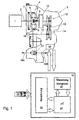
- FIG. 1 shows a system diagram consisting of a drive unit 1, for example an internal combustion engine, a CVT 3 and an electronic control unit 19.
- the CVT 3 is driven by the drive unit 1 via a drive shaft 2.
- the drive shaft 2 drives a starting unit.
- 1 shows a hydrodynamic converter 4 as the starting unit.
- the hydrodynamic converter 4 consists of a pump wheel 5, turbine wheel 6 and stator wheel 7.
- a converter lock-up clutch is shown without reference numerals.
- a pump 8 is connected to the pump wheel 5 of the hydrodynamic converter 4.
- the pump 8 conveys the hydraulic medium from the lubricant sump to the actuators of the CVT 3.
- the turbine wheel 6 or the converter lock-up clutch drives a first shaft 9.
- This shaft 9 in turn drives a forward / reverse drive unit 10.
- the output variable of the forward / reverse driving unit is a second shaft 11.
- the second shaft 11 is connected to the variator.
- the variator consists of a first pair of conical disks 12, a second pair of conical disks 14 and a wrap-around member 13.
- the wrap-around member 13 runs between the two conical disk pairs 12 and 14 .
- the gear ratio is changed by changing the position of the displaceable second cone pulley. As is known, this changes the running radius of the wrapping member 13 and thus the translation.
- the variator is connected to an output shaft 15.
- An intermediate shaft 16 is connected to the output shaft 15 via a gear pair. The intermediate shaft 16 serves to reverse the direction of rotation and to adjust the torque and speed.
- the intermediate shaft 16 is connected to the differential 17 via a gear pair.
- the output variable of the differential 17 is the two axle half-shafts 18A and 18B, which lead to the drive wheels of the vehicle.
- the electronic control unit 19 controls the CVT 3 via electromagnetic actuators (not shown).
- the microcontroller 20, a function block calculation 22 and a function block control actuators 21 are shown as function blocks of the electronic control unit 19.
- Input variables 23 are connected to the electronic control unit 19. Input variables 23 are, for example, the signal of a throttle valve, the signal of the speed of the drive unit, the signal of the vehicle speed and the speed signals of the conical disk pairs.
- the micro-controller 20 uses the function block 22 to calculate the function parameters for the CVT 3 from the input variables 23.
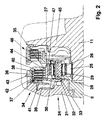
- FIG. 2 shows a section of the forward / reverse driving unit 10 from FIG. 1.
- This essentially consists of a first shaft 9, a second shaft 11, a planetary gear 24, a brake 34 and a clutch 46.
- a first conical disk 45 is made in one piece with the second shaft 11.
- the planetary gear 24 is composed of a sun gear 25, a plurality of planet gears 26 and a ring gear 27.
- the planet gears 26 are each rotatably seated on a pin 29.
- the planet gears 26 are driven via a common first planetary web 28, the first planetary web 28 being integral with the first shaft 9 is executed.
- a second planet carrier 47 leads to the inner disk carrier of the clutch 46.
- the first and second planet carriers can be made in one piece.
- the two planetary webs can be designed, for example, as a sheet metal part and can be connected to one another in one piece by means of shaped tabs.
- the ring gear 27 is connected to an inner disk carrier 35 of the brake 34.
- the brake 34 is composed of the inner disk carrier 35, the inner disk 37, outer disk 38, outer disk carrier 36, end disk 40, locking ring 43, toothing 42, piston 39 with resetting device 41.
- a disk spring is shown as resetting device 41.
- the toothing of the planetary gear 24 is designed as a helical toothing.
- the ring gear 27 is integrally connected to a thrust washer 30. The ring gear 27 is thus supported via the thrust washer 30 either on a stationary wall 31 or on the first planetary web 28.
- the thrust washer 30 is supported in the radial direction on a surface 33 of the stationary wall 31.
- a rotating part, shaft or the like can also be used as a support.
- the ring gear 27 is fixed in addition to being supported by the planet in the radial direction.
- the thrust washer 30 can also be supported radially by means of a bearing arrangement, for example ball bearings.
- the clutch 46 or the brake 34 is used for forward / reverse switching.
- the clutch 46 When the clutch 46 is closed, the planetary gear 24 rotates as a whole.
- the conical disk 45 and the second shaft 11 thus rotate at the same speed and in the same direction of rotation as the first shaft 9.
- the brake 34 When the brake 34 is closed, the planet gears 26 roll on the fixed ring gear 27 and drive the sun 25 when the direction of rotation is reversed.
- Both clutch 46 and brake 34 are designed in a multi-plate design.
- the clutch 46 shows an embodiment according to the prior art, in which an end plate is secured against axial displacement via a locking ring in the outer plate carrier.
- the brake 34 shows a solution according to the invention in which the outer disk carrier 36 and the end disk 40 are made in one piece.
- the end lamella 40 has a collar 44. This collar has a shorter distance from the central axis of the first shaft 9 than the central axis of the inner disk carrier 35 from the central axis of the first shaft 9. This collar prevents the inner disk carrier from falling out during assembly.
- the outer disk carrier 36 is connected to the stationary wall 31 via a toothing 42. Arranged above it as an axial securing means is the securing ring 43.
- the two solutions according to the invention can be used for with every planetary gear and with every planetary gear Use clutch / brake assembly.
Landscapes
- Engineering & Computer Science (AREA)
- General Engineering & Computer Science (AREA)
- Mechanical Engineering (AREA)
- Transmission Devices (AREA)
- Retarders (AREA)
- General Details Of Gearings (AREA)
Claims (4)
- Ensemble composé d'un premier arbre (9) et d'un engrenage planétaire (24) comprenant au moins une roue solaire (25), plusieurs roues planétaires (26) supportées par un porte-pignons satellites et au moins une roue à denture intérieure (27), dans lequelcaractérisé en ce queles roues planétaires (26) sont montées chacune de façon pivotante sur un axe (29),les axes (29) sont logés dans un premier et un deuxième porte-satellites (28, 47) avec lesquels ils forment ensemble le porte-pignons satellites,la roue solaire (25), les roues planétaires (26) et la roue à denture intérieure (27) s'engrènent,le premier arbre (9) entraíne soit la roue solaire (25), soit le premier porte-satellites (28),un disque de démarrage (30) disposé dans le sens vertical est relié sous forme de monobloc à la roue à denture intérieure (27),le rayon intérieur du disque de démarrage (30) correspond approximativement à la distance entre la ligne centrale du premier arbre (9) et la ligne centrale des axes (29), etle disque de démarrage (30) s'appuie dans le sens axial soit à une paroi fixe (31) soit par l'intermédiaire d'un disque (32) sur le premier porte-satellites (28),le disque de démarrage (30) s'appuie dans le sens radial par l'intermédiaire d'une surface (33) sur la paroi fixe (31), respectivement sur le premier arbre.
- Ensemble selon la revendication 1, caractérisé en ce que le disque de démarrage (30) s'appuie dans le sens radial par l'intermédiaire d'un ensemble de paliers sur la paroi fixe (31), respectivement sur le premier arbre, en ce que l'ensemble de paliers se trouve entre la surface (33) sur le diamètre intérieur du disque de démarrage (30) et la paroi fixe (31), respectivement le premier arbre.
- Ensemble composé d'un premier arbre (9) et d'un engrenage planétaire (24) comprenant au moins une roue solaire (25), plusieurs roues planétaires (26) supportées par un porte-pignons satellites et au moins une roue à denture intérieure (27), dans lequelcaractérisé en ce queles roues planétaires (26) sont montées chacune de façon pivotante sur un axe (29),les axes (29) sont logés dans un premier et un deuxième porte-satellites (28, 47) avec lesquels ils forment ensemble le porte-pignons satellites,la roue solaire (25), les roues planétaires (26) et la roue à denture intérieure (27) s'engrènent,le premier arbre (9) entraíne soit la roue solaire (25), soit le premier porte-satellites (28),la roue à denture intérieure (27) ou les axes (29) sont reliés de façon non rotative à un support de disques intérieurs (35) d'un embrayage (46) ou d'un frein (34) ayant une construction du type à disques,l'embrayage (46) ou le frein (34) se compose du support de disques intérieurs (35) et d'un support de disques extérieurs (35, 36),au support de disques intérieurs (35) sont associés des disques intérieurs (37) et au support de disques extérieurs (36) sont associés des disques extérieurs (38),les disques intérieurs (37) et les disques extérieurs (38) sont mobiles dans le sens axial et sont reliés de façon non rotative au support des disques intérieurs, respectivement extérieurs (35, 36),l'embrayage (46) ou le frein (34) est fermé par le fait qu'un piston (39) pousse les disques extérieurs et intérieurs (37, 38) contre un disque terminal (40), qui est un disque extérieur (38),l'embrayage (46) ou le frein (34) est ouvert par le fait que le piston (39) est repoussé dans sa position de repos par l'intermédiaire d'un dispositif de rappel (41), etle support des disques extérieurs (36) et le disque terminal (40) sont réalisés en un seul bloc,le support de disques extérieurs (36) présente une denture (42) à sa circonférence extérieure,le support de disques extérieurs (36) est fixé par l'intermédiaire de la denture (42) dans le sens radial et par l'intermédiaire d'un anneau d'arrêt (43) dans le sens axial, etle disque terminal (40) présente dans le sens radial en direction du premier arbre (9), un épaulement (44) qui a une distance vers le premier arbre (9) plus courte que la ligne centrale du support des disques intérieurs (35) vers la ligne centrale du premier arbre (9).
- Ensemble selon la revendication 3, caractérisé en ce que le premier et le deuxième porte-satellites (28, 47) sont réalisés comme pièces formées en tôle et sont reliés entre eux en un seul bloc par des colliers réalisés par formage.
Applications Claiming Priority (1)
| Application Number | Priority Date | Filing Date | Title |
|---|---|---|---|
| PCT/EP1996/001675 WO1997040290A1 (fr) | 1996-04-22 | 1996-04-22 | Train planetaire et ensemble embrayage-frein |
Publications (2)
| Publication Number | Publication Date |
|---|---|
| EP0895566A1 EP0895566A1 (fr) | 1999-02-10 |
| EP0895566B1 true EP0895566B1 (fr) | 2000-01-12 |
Family
ID=8166205
Family Applications (1)
| Application Number | Title | Priority Date | Filing Date |
|---|---|---|---|
| EP96914100A Expired - Lifetime EP0895566B1 (fr) | 1996-04-22 | 1996-04-22 | Train planetaire et ensemble embrayage-frein |
Country Status (5)
| Country | Link |
|---|---|
| US (1) | US6086504A (fr) |
| EP (1) | EP0895566B1 (fr) |
| JP (1) | JP2000508743A (fr) |
| DE (1) | DE59604201D1 (fr) |
| WO (1) | WO1997040290A1 (fr) |
Cited By (1)
| Publication number | Priority date | Publication date | Assignee | Title |
|---|---|---|---|---|
| US9243690B2 (en) | 2012-02-29 | 2016-01-26 | Auburn Gear, Inc. | Multispeed drive unit |
Families Citing this family (24)
| Publication number | Priority date | Publication date | Assignee | Title |
|---|---|---|---|---|
| US6907951B2 (en) * | 2000-03-07 | 2005-06-21 | Arctic Cat, Inc. | Snowmobile planetary drive system |
| US6742618B2 (en) * | 2000-03-07 | 2004-06-01 | Arctic Cat, Inc. | Snowmobile planetary drive system |
| JP2002250367A (ja) * | 2001-02-22 | 2002-09-06 | Exedy Corp | 多板クラッチ装置 |
| DE102007042713A1 (de) * | 2007-09-07 | 2009-03-12 | Zf Friedrichshafen Ag | Anordnung eines Planetenradsatzes mit einem axial benachbarten Schaltelement in einem Getriebe |
| US8920282B2 (en) * | 2011-02-25 | 2014-12-30 | Schaeffler Technologies Gmbh & Co. Kg | Transmission with a common actuator for two clutches |
| US9347532B2 (en) | 2012-01-19 | 2016-05-24 | Dana Limited | Tilting ball variator continuously variable transmission torque vectoring device |
| EP2815152A1 (fr) | 2012-02-15 | 2014-12-24 | Dana Limited | Transmission et chaîne cinématique ayant une transmission à variation continue par variateur à bille d'inclinaison |
| CN104769325A (zh) * | 2012-09-06 | 2015-07-08 | 德纳有限公司 | 具有连续式或无限式无级变速机构驱动件的变速器 |
| US9052000B2 (en) | 2012-09-07 | 2015-06-09 | Dana Limited | Ball type CVT/IVT including planetary gear sets |
| US9638296B2 (en) | 2012-09-07 | 2017-05-02 | Dana Limited | Ball type CVT including a direct drive mode |
| CN104769329B (zh) | 2012-09-07 | 2017-06-23 | 德纳有限公司 | 球型连续式无级变速器/无限式无级变速器 |
| US9353842B2 (en) | 2012-09-07 | 2016-05-31 | Dana Limited | Ball type CVT with powersplit paths |
| CN104755812A (zh) | 2012-09-07 | 2015-07-01 | 德纳有限公司 | 包括动力分流路径的基于球型cvp的ivt |
| JP6247690B2 (ja) | 2012-09-07 | 2017-12-13 | デーナ リミテッド | 出力連結動力経路を有するボール式cvt |
| US10030748B2 (en) | 2012-11-17 | 2018-07-24 | Dana Limited | Continuously variable transmission |
| WO2014124063A1 (fr) | 2013-02-08 | 2014-08-14 | Microsoft Corporation | Service omniprésent de fourniture de mises à jour spécifiques à des dispositifs |
| WO2014159755A2 (fr) | 2013-03-14 | 2014-10-02 | Dana Limited | Transmission à variation continue de type courroie |
| EP2971860A4 (fr) | 2013-03-14 | 2016-12-28 | Dana Ltd | Transmission à variation continue et entraînement à variateur de transmission à variation continue |
| JP2016520782A (ja) | 2013-06-06 | 2016-07-14 | デーナ リミテッド | 3モード前輪駆動および後輪駆動連続可変遊星トランスミッション |
| US10088022B2 (en) | 2013-11-18 | 2018-10-02 | Dana Limited | Torque peak detection and control mechanism for a CVP |
| WO2015073883A1 (fr) | 2013-11-18 | 2015-05-21 | Dana Limited | Transmission variable infinie dotée d'un ensemble de train planétaire |
| US10030594B2 (en) | 2015-09-18 | 2018-07-24 | Dana Limited | Abuse mode torque limiting control method for a ball-type continuously variable transmission |
| DE102016221748A1 (de) * | 2016-11-07 | 2018-05-09 | Schaeffler Technologies AG & Co. KG | Kupplungseinrichtung |
| KR102173762B1 (ko) * | 2018-11-26 | 2020-11-04 | 현대트랜시스 주식회사 | 변속기용 브레이크 장치 |
Family Cites Families (12)
| Publication number | Priority date | Publication date | Assignee | Title |
|---|---|---|---|---|
| US3097546A (en) * | 1963-07-16 | Transmission mechanism | ||
| US2558738A (en) * | 1945-08-07 | 1951-07-03 | Wright Acronautical Corp | Multispeed transmission |
| US3131582A (en) * | 1961-02-20 | 1964-05-05 | Borg Warner | Transmission mechanism |
| US3359833A (en) * | 1964-11-25 | 1967-12-26 | Borg Warner | Transmission controls |
| US3669232A (en) * | 1970-09-03 | 1972-06-13 | Caterpillar Tractor Co | Retraction spring for clutches, brakes and like devices |
| DE2403876B2 (de) * | 1974-01-28 | 1979-09-06 | Zahnradfabrik Friedrichshafen Ag, 7990 Friedrichshafen | Kupplungseinrichtung für unter Last schaltbare Planetenradgetriebe, insbesondere für selbsttätig schaltende Kraftf ahrzeug-Planetenradgetriebe |
| JPS57137757A (en) * | 1981-02-16 | 1982-08-25 | Aisin Warner Ltd | Controller for fluid pressure of belt type stepless change gear |
| DE3129414A1 (de) * | 1981-07-25 | 1983-02-10 | Ford-Werke AG, 5000 Köln | Umlaufraeder-wendegetriebe fuer ein stufenlos regelbares zugorgangetriebe eines kraftfahrzeuges |
| US4680979A (en) * | 1984-12-20 | 1987-07-21 | Mitsubishi Denki Kabushiki Kaisha | Planetary gear starter |
| JPH0465963U (fr) * | 1990-10-09 | 1992-06-09 | ||
| BE1005602A3 (nl) * | 1992-02-18 | 1993-11-16 | Volvo Car Sint Truiden Nv | Planetaire overbrenging, alsmede transmissie voor motorvoertuigen die met zulke overbrenging is uitgerust. |
| BE1008501A3 (nl) * | 1994-07-13 | 1996-05-07 | Vcst Nv | Transmissie-eenheid voor motorvoertuigen. |
-
1996
- 1996-04-22 US US09/155,058 patent/US6086504A/en not_active Expired - Fee Related
- 1996-04-22 WO PCT/EP1996/001675 patent/WO1997040290A1/fr active IP Right Grant
- 1996-04-22 JP JP09537630A patent/JP2000508743A/ja not_active Ceased
- 1996-04-22 DE DE59604201T patent/DE59604201D1/de not_active Expired - Fee Related
- 1996-04-22 EP EP96914100A patent/EP0895566B1/fr not_active Expired - Lifetime
Cited By (1)
| Publication number | Priority date | Publication date | Assignee | Title |
|---|---|---|---|---|
| US9243690B2 (en) | 2012-02-29 | 2016-01-26 | Auburn Gear, Inc. | Multispeed drive unit |
Also Published As
| Publication number | Publication date |
|---|---|
| DE59604201D1 (de) | 2000-02-17 |
| WO1997040290A1 (fr) | 1997-10-30 |
| JP2000508743A (ja) | 2000-07-11 |
| EP0895566A1 (fr) | 1999-02-10 |
| US6086504A (en) | 2000-07-11 |
Similar Documents
| Publication | Publication Date | Title |
|---|---|---|
| EP0895566B1 (fr) | Train planetaire et ensemble embrayage-frein | |
| DE60009769T2 (de) | Stufenloses Toroidgetriebe | |
| AT503360B1 (de) | Getriebeanordnung zur variablen drehmomentverteilung | |
| DE102005061267B4 (de) | Differentialanordnung mit zwei gemeinsam betätigten Axialverstellvorrichtungen | |
| DE102005004290B4 (de) | Getriebemodul zur variablen Drehmomentverteilung | |
| DE2029515C3 (de) | Antriebsblock für Kraftfahrzeuge | |
| AT510922B1 (de) | Getriebeanordnung zur variablen drehmomentverteilung | |
| DE2633090C2 (de) | Hydrostatisch-mechanisches Getriebe mit Leistungsverzweigung für Kraftfahrzeuge | |
| DE10160026B9 (de) | Betätigungsmechanismus zur Axialverstellung mit doppelter Funktion | |
| DE2325699A1 (de) | Getriebe fuer kraftfahrzeuge, insbesondere fuer schlepper | |
| DE4321476C2 (de) | Stufenloses Reibrollengetriebe mit toroidförmigen Reibscheiben | |
| DE69707633T2 (de) | Planetengetriebe | |
| DE4206087C2 (de) | Hydromechanischer Radantrieb | |
| DE10046926A1 (de) | Koaxiales Traktionsgetriebe mit einer einzigen Betriebsart und einem über Zahnräder hergestellten, neutralen Zustand | |
| DE4415739A1 (de) | Antriebsverbindung für die Einstellscheibe eines stetig veränderlichen Getriebes | |
| DE19961275C2 (de) | Automatgetriebe für ein Kraftfahrzeug | |
| WO2005083300A1 (fr) | Engrenage toroidal pour un vehicule | |
| EP2021646A1 (fr) | Dispositif de réglage axial d'au moins un élément de commande à lamelles | |
| DE19515616A1 (de) | Planetengetriebe und Kupplungs-/Bremsanordnung | |
| EP1656514B1 (fr) | Transmission reglable en continu | |
| DE68906424T2 (de) | Geraet zur stufenlosen geschwindigkeitsaenderung. | |
| EP1174643B1 (fr) | Engrenage à friction variable en continu | |
| EP1322862B1 (fr) | Dispositif de demarrage | |
| DE10359858A1 (de) | Stufenlos einstellbares Getriebe | |
| DE2950208C2 (de) | Stufenlos einstellbares, mechanisches Verzweigungsgetriebe |
Legal Events
| Date | Code | Title | Description |
|---|---|---|---|
| PUAI | Public reference made under article 153(3) epc to a published international application that has entered the european phase |
Free format text: ORIGINAL CODE: 0009012 |
|
| 17P | Request for examination filed |
Effective date: 19980826 |
|
| AK | Designated contracting states |
Kind code of ref document: A1 Designated state(s): DE FR GB SE |
|
| 17Q | First examination report despatched |
Effective date: 19990202 |
|
| GRAG | Despatch of communication of intention to grant |
Free format text: ORIGINAL CODE: EPIDOS AGRA |
|
| GRAG | Despatch of communication of intention to grant |
Free format text: ORIGINAL CODE: EPIDOS AGRA |
|
| GRAH | Despatch of communication of intention to grant a patent |
Free format text: ORIGINAL CODE: EPIDOS IGRA |
|
| GRAH | Despatch of communication of intention to grant a patent |
Free format text: ORIGINAL CODE: EPIDOS IGRA |
|
| GRAA | (expected) grant |
Free format text: ORIGINAL CODE: 0009210 |
|
| AK | Designated contracting states |
Kind code of ref document: B1 Designated state(s): DE FR GB SE |
|
| GBT | Gb: translation of ep patent filed (gb section 77(6)(a)/1977) |
Effective date: 20000112 |
|
| REF | Corresponds to: |
Ref document number: 59604201 Country of ref document: DE Date of ref document: 20000217 |
|
| PGFP | Annual fee paid to national office [announced via postgrant information from national office to epo] |
Ref country code: GB Payment date: 20000323 Year of fee payment: 5 |
|
| PGFP | Annual fee paid to national office [announced via postgrant information from national office to epo] |
Ref country code: SE Payment date: 20000420 Year of fee payment: 5 |
|
| ET | Fr: translation filed | ||
| PLBE | No opposition filed within time limit |
Free format text: ORIGINAL CODE: 0009261 |
|
| STAA | Information on the status of an ep patent application or granted ep patent |
Free format text: STATUS: NO OPPOSITION FILED WITHIN TIME LIMIT |
|
| 26N | No opposition filed | ||
| PG25 | Lapsed in a contracting state [announced via postgrant information from national office to epo] |
Ref country code: GB Free format text: LAPSE BECAUSE OF NON-PAYMENT OF DUE FEES Effective date: 20010422 |
|
| PG25 | Lapsed in a contracting state [announced via postgrant information from national office to epo] |
Ref country code: SE Free format text: LAPSE BECAUSE OF NON-PAYMENT OF DUE FEES Effective date: 20010423 |
|
| EUG | Se: european patent has lapsed |
Ref document number: 96914100.1 |
|
| GBPC | Gb: european patent ceased through non-payment of renewal fee |
Effective date: 20010422 |
|
| PGFP | Annual fee paid to national office [announced via postgrant information from national office to epo] |
Ref country code: FR Payment date: 20020423 Year of fee payment: 7 |
|
| PG25 | Lapsed in a contracting state [announced via postgrant information from national office to epo] |
Ref country code: FR Free format text: LAPSE BECAUSE OF NON-PAYMENT OF DUE FEES Effective date: 20031231 |
|
| REG | Reference to a national code |
Ref country code: FR Ref legal event code: ST |
|
| PGFP | Annual fee paid to national office [announced via postgrant information from national office to epo] |
Ref country code: DE Payment date: 20080502 Year of fee payment: 13 |
|
| PG25 | Lapsed in a contracting state [announced via postgrant information from national office to epo] |
Ref country code: DE Free format text: LAPSE BECAUSE OF NON-PAYMENT OF DUE FEES Effective date: 20091103 |