EP0895566B1 - Planetary gear and clutch-brake arrangement - Google Patents
Planetary gear and clutch-brake arrangement Download PDFInfo
- Publication number
- EP0895566B1 EP0895566B1 EP96914100A EP96914100A EP0895566B1 EP 0895566 B1 EP0895566 B1 EP 0895566B1 EP 96914100 A EP96914100 A EP 96914100A EP 96914100 A EP96914100 A EP 96914100A EP 0895566 B1 EP0895566 B1 EP 0895566B1
- Authority
- EP
- European Patent Office
- Prior art keywords
- shaft
- planet
- carrier
- ring gear
- clutch
- Prior art date
- Legal status (The legal status is an assumption and is not a legal conclusion. Google has not performed a legal analysis and makes no representation as to the accuracy of the status listed.)
- Expired - Lifetime
Links
Images
Classifications
-
- F—MECHANICAL ENGINEERING; LIGHTING; HEATING; WEAPONS; BLASTING
- F16—ENGINEERING ELEMENTS AND UNITS; GENERAL MEASURES FOR PRODUCING AND MAINTAINING EFFECTIVE FUNCTIONING OF MACHINES OR INSTALLATIONS; THERMAL INSULATION IN GENERAL
- F16H—GEARING
- F16H37/00—Combinations of mechanical gearings, not provided for in groups F16H1/00 - F16H35/00
- F16H37/02—Combinations of mechanical gearings, not provided for in groups F16H1/00 - F16H35/00 comprising essentially only toothed or friction gearings
- F16H37/021—Combinations of mechanical gearings, not provided for in groups F16H1/00 - F16H35/00 comprising essentially only toothed or friction gearings toothed gearing combined with continuous variable friction gearing
- F16H37/022—Combinations of mechanical gearings, not provided for in groups F16H1/00 - F16H35/00 comprising essentially only toothed or friction gearings toothed gearing combined with continuous variable friction gearing the toothed gearing having orbital motion
-
- F—MECHANICAL ENGINEERING; LIGHTING; HEATING; WEAPONS; BLASTING
- F16—ENGINEERING ELEMENTS AND UNITS; GENERAL MEASURES FOR PRODUCING AND MAINTAINING EFFECTIVE FUNCTIONING OF MACHINES OR INSTALLATIONS; THERMAL INSULATION IN GENERAL
- F16H—GEARING
- F16H3/00—Toothed gearings for conveying rotary motion with variable gear ratio or for reversing rotary motion
- F16H3/44—Toothed gearings for conveying rotary motion with variable gear ratio or for reversing rotary motion using gears having orbital motion
- F16H3/46—Gearings having only two central gears, connected by orbital gears
- F16H3/60—Gearings for reversal only
-
- F—MECHANICAL ENGINEERING; LIGHTING; HEATING; WEAPONS; BLASTING
- F16—ENGINEERING ELEMENTS AND UNITS; GENERAL MEASURES FOR PRODUCING AND MAINTAINING EFFECTIVE FUNCTIONING OF MACHINES OR INSTALLATIONS; THERMAL INSULATION IN GENERAL
- F16H—GEARING
- F16H57/00—General details of gearing
- F16H57/08—General details of gearing of gearings with members having orbital motion
Definitions
- the invention relates to a planetary gear and Clutch / brake arrangement, preferably for a stepless Automatic transmission, according to the preamble of claim 1 or 3rd
- CVT Continuously variable automatic transmission
- starting unit for example a crankshaft.
- a starting clutch serves as the starting unit or a hydrodynamic converter.
- the forward / reverse drive unit serves to reverse the direction of rotation of the drive shaft for reversing.
- the forward / reverse drive unit is mostly as a planetary gear executed. This consists of at least one sun gear, several planets, a ring gear, a brake and one Coupling of the multi-plate design.
- the variator consists of two Cone pulley pairs and a wrap.
- Each Conical disc pair in turn consists of an axial Direction of the first conical disk and one in axially displaceable second conical disk. Between the belt element runs these conical pulley pairs, for example a push link belt. About the adjustment the second conical disc changes the running radius of the wrapping element and thus the translation of the CVT.
- a CVT with a forward / reverse driving unit is known from Automobiltechnische Zeitschrift 96 (1994) 6, page 380, Figure 3.
- a first shaft driven by the pump wheel of the hydrodynamic converter drives the planet wheels connected via a common first planet web.
- Each planet gear is rotatably mounted on a pin.
- the planet gears mesh on the one hand with a sun gear which is located on a second shaft and on the other hand with a ring gear.
- the ring gear can be fixed against a fixed wall, for example the gearbox housing, by means of a multi-disc brake.
- the second planetary web is connected to the first conical disk via a clutch of the lamella type.
- the planetary gearbox rotates as a whole with gear ratio 1 and the same direction of rotation as the first shaft.
- the brake is closed, the direction of rotation is reversed for reversing.
- the gears of the planetary gear are helical.
- the helical toothing planet / ring gear causes axial forces on the ring gear.
- the ring gear is supported in the axial direction either on the second planetary web, which is connected to the clutch, or on the stationary wall.
- GB-A-2 102 515 is a planetary gear according to the features in the preamble of claim 1 described, in which a arranged in the vertical direction Thrust washer is integrally connected to the ring gear.
- the inner radius of the thrust washer corresponds approximately to this the distance between the central axis of the first shaft and the central axis the bolt.
- the thrust washer is supported in the axial direction either on a fixed wall or on the planet bridge of the reversing gear.
- the invention has for its object a planetary gearbox, whose ring gear is connected to an inner disk carrier is to develop further.
- the first solution to the problem according to the invention is in the fact that one is made in one piece with a ring gear Thrust washer, through which the axial force of the ring gear either on a fixed wall or on a planet bridge is supported, in addition in the radial direction over a surface on the inner diameter of the thrust washer and as a counterpart on a surface of the fixed wall or supports a shaft.
- Thrust washer through which the ring gear is only stored over the planets is thereby achieved the advantage that the ring gear is additionally fixed in the radial direction.
- a second solution to the object is achieved from an arrangement of a planetary gear in which the ring gear or the pin on which the planet gears respectively are rotatably mounted with the inner disk carrier a clutch or brake of the multi-disc design is connected in a rotationally fixed manner is.
- the plates of the clutch or brake are here by a piston actuating against an end plate be pressed.
- the clutch outer disk carrier is made in one piece with the end lamella.
- the end lamella has a collar radially in the direction of the first shaft.
- This covenant has a shorter distance from the first Shaft as the central axis of the inner disk carrier to the central axis first wave. This has the advantage of that the inner disk carrier through the collar against falling out is secured during assembly.
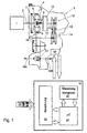
- FIG. 1 shows a system diagram consisting of a drive unit 1, for example an internal combustion engine, a CVT 3 and an electronic control unit 19.
- the CVT 3 is driven by the drive unit 1 via a drive shaft 2.
- the drive shaft 2 drives a starting unit.
- 1 shows a hydrodynamic converter 4 as the starting unit.
- the hydrodynamic converter 4 consists of a pump wheel 5, turbine wheel 6 and stator wheel 7.
- a converter lock-up clutch is shown without reference numerals.
- a pump 8 is connected to the pump wheel 5 of the hydrodynamic converter 4.
- the pump 8 conveys the hydraulic medium from the lubricant sump to the actuators of the CVT 3.
- the turbine wheel 6 or the converter lock-up clutch drives a first shaft 9.
- This shaft 9 in turn drives a forward / reverse drive unit 10.
- the output variable of the forward / reverse driving unit is a second shaft 11.
- the second shaft 11 is connected to the variator.
- the variator consists of a first pair of conical disks 12, a second pair of conical disks 14 and a wrap-around member 13.
- the wrap-around member 13 runs between the two conical disk pairs 12 and 14 .
- the gear ratio is changed by changing the position of the displaceable second cone pulley. As is known, this changes the running radius of the wrapping member 13 and thus the translation.
- the variator is connected to an output shaft 15.
- An intermediate shaft 16 is connected to the output shaft 15 via a gear pair. The intermediate shaft 16 serves to reverse the direction of rotation and to adjust the torque and speed.
- the intermediate shaft 16 is connected to the differential 17 via a gear pair.
- the output variable of the differential 17 is the two axle half-shafts 18A and 18B, which lead to the drive wheels of the vehicle.
- the electronic control unit 19 controls the CVT 3 via electromagnetic actuators (not shown).
- the microcontroller 20, a function block calculation 22 and a function block control actuators 21 are shown as function blocks of the electronic control unit 19.
- Input variables 23 are connected to the electronic control unit 19. Input variables 23 are, for example, the signal of a throttle valve, the signal of the speed of the drive unit, the signal of the vehicle speed and the speed signals of the conical disk pairs.
- the micro-controller 20 uses the function block 22 to calculate the function parameters for the CVT 3 from the input variables 23.
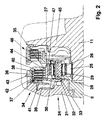
- FIG. 2 shows a section of the forward / reverse driving unit 10 from FIG. 1.
- This essentially consists of a first shaft 9, a second shaft 11, a planetary gear 24, a brake 34 and a clutch 46.
- a first conical disk 45 is made in one piece with the second shaft 11.
- the planetary gear 24 is composed of a sun gear 25, a plurality of planet gears 26 and a ring gear 27.
- the planet gears 26 are each rotatably seated on a pin 29.
- the planet gears 26 are driven via a common first planetary web 28, the first planetary web 28 being integral with the first shaft 9 is executed.
- a second planet carrier 47 leads to the inner disk carrier of the clutch 46.
- the first and second planet carriers can be made in one piece.
- the two planetary webs can be designed, for example, as a sheet metal part and can be connected to one another in one piece by means of shaped tabs.
- the ring gear 27 is connected to an inner disk carrier 35 of the brake 34.
- the brake 34 is composed of the inner disk carrier 35, the inner disk 37, outer disk 38, outer disk carrier 36, end disk 40, locking ring 43, toothing 42, piston 39 with resetting device 41.
- a disk spring is shown as resetting device 41.
- the toothing of the planetary gear 24 is designed as a helical toothing.
- the ring gear 27 is integrally connected to a thrust washer 30. The ring gear 27 is thus supported via the thrust washer 30 either on a stationary wall 31 or on the first planetary web 28.
- the thrust washer 30 is supported in the radial direction on a surface 33 of the stationary wall 31.
- a rotating part, shaft or the like can also be used as a support.
- the ring gear 27 is fixed in addition to being supported by the planet in the radial direction.
- the thrust washer 30 can also be supported radially by means of a bearing arrangement, for example ball bearings.
- the clutch 46 or the brake 34 is used for forward / reverse switching.
- the clutch 46 When the clutch 46 is closed, the planetary gear 24 rotates as a whole.
- the conical disk 45 and the second shaft 11 thus rotate at the same speed and in the same direction of rotation as the first shaft 9.
- the brake 34 When the brake 34 is closed, the planet gears 26 roll on the fixed ring gear 27 and drive the sun 25 when the direction of rotation is reversed.
- Both clutch 46 and brake 34 are designed in a multi-plate design.
- the clutch 46 shows an embodiment according to the prior art, in which an end plate is secured against axial displacement via a locking ring in the outer plate carrier.
- the brake 34 shows a solution according to the invention in which the outer disk carrier 36 and the end disk 40 are made in one piece.
- the end lamella 40 has a collar 44. This collar has a shorter distance from the central axis of the first shaft 9 than the central axis of the inner disk carrier 35 from the central axis of the first shaft 9. This collar prevents the inner disk carrier from falling out during assembly.
- the outer disk carrier 36 is connected to the stationary wall 31 via a toothing 42. Arranged above it as an axial securing means is the securing ring 43.
- the two solutions according to the invention can be used for with every planetary gear and with every planetary gear Use clutch / brake assembly.
Landscapes
- Engineering & Computer Science (AREA)
- General Engineering & Computer Science (AREA)
- Mechanical Engineering (AREA)
- Transmission Devices (AREA)
Description
Die Erfindung betrifft ein Planetengetriebe und eine
Kupplungs-/Bremsanordnung, vorzugsweise für ein stufenloses
Automatgetriebe, nach dem Oberbegriff von Anspruch 1
bzw. 3.The invention relates to a planetary gear and
Clutch / brake arrangement, preferably for a stepless
Automatic transmission, according to the preamble of
Stufenlose Automatgetriebe, nachfolgend CVT genannt (Continuously Variable Transmission), bestehen aus folgenden Baugruppen: Anfahreinheit, Vorwärts-/Rückwärtsfahreinheit, Variator, Zwischenwelle und Differential. Üblicherweise werden derartige CVT von einer Brennkraftmaschine über eine Antriebswelle, zum Beispiel Kurbelwelle, angetrieben. Als Anfahreinheit dient entweder eine Anfahrkupplung oder ein hydrodynamischer Wandler. Die Vorwärts-/Rückwärtsfahreinheit dient der Drehrichtungsumkehr der Antriebswelle für die Rückwärtsfahrt. Die Vorwärts-/Rückwärtsfahreinheit ist meist als ein Planetenwendegetriebe ausgeführt. Dieses besteht aus mindestens einem Sonnenrad, mehreren Planeten, einem Hohlrad, einer Bremse und einer Kupplung der Lamellenbauart. Der Variator besteht aus zwei Kegelscheibenpaaren und einem Umschlingungsorgan. Jedes Kegelscheibenpaar wiederum besteht aus einer in axialer Richtung feststehenden ersten Kegelscheibe und einer in axialer Richtung verschiebbaren zweiten Kegelscheibe. Zwischen diesen Kegelscheibenpaaren läuft das Umschlingungsorgan, zum Beispiel ein Schubgliederband. Über die Verstellung der zweiten Kegelscheibe ändert sich der Laufradius des Umschlingungsorgans und somit die Übersetzung des CVT.Continuously variable automatic transmission, hereinafter called CVT (Continuously Variable Transmission) consist of the following Assemblies: starting unit, forward / reverse driving unit, Variator, intermediate shaft and differential. Usually such CVT are from an internal combustion engine driven by a drive shaft, for example a crankshaft. Either a starting clutch serves as the starting unit or a hydrodynamic converter. The forward / reverse drive unit serves to reverse the direction of rotation of the drive shaft for reversing. The forward / reverse drive unit is mostly as a planetary gear executed. This consists of at least one sun gear, several planets, a ring gear, a brake and one Coupling of the multi-plate design. The variator consists of two Cone pulley pairs and a wrap. Each Conical disc pair in turn consists of an axial Direction of the first conical disk and one in axially displaceable second conical disk. Between the belt element runs these conical pulley pairs, for example a push link belt. About the adjustment the second conical disc changes the running radius of the wrapping element and thus the translation of the CVT.
Aus der Automobiltechnischen Zeitschrift 96 (1994) 6,
Seite 380, Bild 3, ist ein CVT mit einer Vorwärts-/Rückwärtsfahreinheit
bekannt. Hierbei treibt eine vom Pumpenrad
des hydrodynamischen Wandlers angetriebene erste Welle die
über einen gemeinsamen ersten Planetensteg verbundenen Planetenräder
an. Jedes Planetenrad ist drehbar auf einem Bolzen
gelagert. Die Planetenräder kämmen zum einen mit einem
Sonnenrad, welches sich auf einer zweiten Welle befindet
und zum anderen mit einem Hohlrad. Das Hohlrad kann über
eine Bremse der Lamellenbauart gegen eine ortsfeste Wand
festgesetzt werden, zum Beispiel dem Getriebegehäuse. Der
zweite Planetensteg ist über eine Kupplung der Lamellenbauart
mit der ersten Kegelscheibe verbunden. Bei geschlossener
Kupplung läuft das Planetenwendegetriebe als Ganzes mit
der Übersetzung 1 und der gleichen Drehrichtung wie die
erste Welle um. Bei geschlossener Bremse erfolgt eine Drehrichtungsumkehr
für die Rückwärtsfahrt.
Üblicherweise sind die Zahnräder des Planetenwendegetriebes
schrägverzahnt. Durch die Schrägverzahnung Planet/Hohlrad
treten axiale Kräfte am Hohlrad auf. Gemäß dem erwähnten
Stand der Technik stützt sich das Hohlrad in axialer Richtung
entweder am zweiten Planetensteg, der mit der Kupplung
verbunden ist, oder an der ortsfesten Wand ab.A CVT with a forward / reverse driving unit is known from Automobiltechnische Zeitschrift 96 (1994) 6, page 380, Figure 3. Here, a first shaft driven by the pump wheel of the hydrodynamic converter drives the planet wheels connected via a common first planet web. Each planet gear is rotatably mounted on a pin. The planet gears mesh on the one hand with a sun gear which is located on a second shaft and on the other hand with a ring gear. The ring gear can be fixed against a fixed wall, for example the gearbox housing, by means of a multi-disc brake. The second planetary web is connected to the first conical disk via a clutch of the lamella type. When the clutch is closed, the planetary gearbox rotates as a whole with
Usually, the gears of the planetary gear are helical. The helical toothing planet / ring gear causes axial forces on the ring gear. According to the prior art mentioned, the ring gear is supported in the axial direction either on the second planetary web, which is connected to the clutch, or on the stationary wall.
In der GB-A-2 102 515 ist entsprechend den Merkmalen im Oberbegriff von Anspruch 1 ein Planetenwendegetriebe
beschrieben, bei dem eine in vertikaler Richtung angeordnete
Anlaufscheibe einstückig mit dem Hohlrad verbunden ist.
Der innere Radius der Anlaufscheibe entspricht hierbei etwa
dem Abstand Mittelachse der ersten Welle zur Mittelachse
der Bolzen. Die Anlaufscheibe stützt sich in axialer Richtung
entweder an einer ortsfesten Wand oder am Planetensteg
des Wendegetriebes ab.In GB-A-2 102 515 is a planetary gear according to the features in the preamble of
Als kompakte Bauausführung eines Planetenwendegetriebes
beschreibt die US-A-3,699,232 entsprechend den Merkmalen im Oberbegriff von Anspruch 3 eine Anordnung, bei der
das Hohlrad gleichzeitig als Innenlamellenträger einer
Kupplung ausgebildet ist. Der Außenlamellenträger und die
Endlamelle der Kupplung sind hierbei einstückig ausgeführt.As a compact design of a planetary gearbox
US-A-3,699,232, according to the features in the preamble of
Die Erfindung hat zur Aufgabe, ein Planetenwendegetriebe, dessen Hohlrad mit einem Innenlamellenträger verbunden ist, weiterzuentwickeln.The invention has for its object a planetary gearbox, whose ring gear is connected to an inner disk carrier is to develop further.
Die erste erfindungsgemäße Lösung der Aufgabe besteht darin, daß sich eine mit einem Hohlrad einstückig ausgeführte Anlaufscheibe, über welche die Axialkraft des Hohlrades entweder an einer ortsfesten Wand oder an einem Planetensteg abgestützt wird, zusätzlich in radialer Richtung über eine Fläche am inneren Durchmesser der Anlaufscheibe und als Gegenstück an einer Fläche der ortsfesten Wand bzw. einer Welle abstützt. Gegenüber dem Stand der Technik, bei dem das Hohlrad ausschließlich über die Planeten gelagert ist, wird hierdurch der Vorteil erzielt, daß das Hohlrad zusätzlich in radialer Richtung fixiert ist.The first solution to the problem according to the invention is in the fact that one is made in one piece with a ring gear Thrust washer, through which the axial force of the ring gear either on a fixed wall or on a planet bridge is supported, in addition in the radial direction over a surface on the inner diameter of the thrust washer and as a counterpart on a surface of the fixed wall or supports a shaft. Compared to the prior art, at which the ring gear is only stored over the planets is thereby achieved the advantage that the ring gear is additionally fixed in the radial direction.
Eine zweite erfindungsgemäße Lösung der Aufgabe geht von einer Anordnung eines Planetengetriebes aus, bei dem das Hohlrad oder der Bolzen, auf den die Planetenräder jeweils drehbar gelagert sind, mit dem Innenlamellenträger einer Kupplung oder Bremse der Lamellenbauart drehfest verbunden ist. Die Lamellen der Kupplung oder Bremse werden hierbei von einem Kolben der Betätigung gegen eine Endlamelle gedrückt werden. Der Außenlamellenträger der Kupplung ist hierbei einstückig mit der Endlamelle ausgeführt.A second solution to the object is achieved from an arrangement of a planetary gear in which the ring gear or the pin on which the planet gears respectively are rotatably mounted with the inner disk carrier a clutch or brake of the multi-disc design is connected in a rotationally fixed manner is. The plates of the clutch or brake are here by a piston actuating against an end plate be pressed. The clutch outer disk carrier is made in one piece with the end lamella.
Erfindungsgemäß wird vorgeschlagen, daß die Endlamelle radial in Richtung der ersten Welle einen Bund aufweist. Dieser Bund hat hierbei einen kürzeren Abstand zur ersten Welle als die Mittelachse des Innenlamellenträgers zur Mittelachse erste Welle. Hierdurch wird der Vorteil erzielt, daß der Innenlamellenträger durch den Bund gegen Herausfallen bei der Montage gesichert ist.According to the invention it is proposed that the end lamella has a collar radially in the direction of the first shaft. This covenant has a shorter distance from the first Shaft as the central axis of the inner disk carrier to the central axis first wave. This has the advantage of that the inner disk carrier through the collar against falling out is secured during assembly.
In der Zeichnung ist ein Ausführungsbeispiel dargestellt.
Es zeigen:
- Fig. 1
- ein Systemschaubild eines CVT und
- Fig. 2
- eine Vorwärts-/Rückwärtsfahreinheit.
Show it:
- Fig. 1
- a system diagram of a CVT and
- Fig. 2
- a forward / reverse drive unit.
Fig. 1 zeigt ein Systemschaubild, bestehend aus einer
Antriebseinheit 1, zum Beispiel Brennkraftmaschine, einem
CVT 3 und einem elektronischen Steuergerät 19.
Das CVT 3 wird von der Antriebseinheit 1 über eine Antriebswelle
2 angetrieben. Die Antriebswelle 2 treibt eine
Anfahreinheit an. In Fig. 1 ist als Anfahreinheit ein hydrodynamischer
Wandler 4 dargestellt. Der hydrodynamische
Wandler 4 besteht bekanntermaßen aus einem Pumpenrad 5,
Turbinenrad 6 und Leitrad 7. Parallel zum hydrodynamischen
Wandler ist eine Wandlerüberbrückungskupplung ohne Bezugszeichen
dargestellt. Mit dem Pumpenrad 5 des hydrodynamischen
Wandlers 4 ist eine Pumpe 8 verbunden. Die Pumpe 8
fördert das Hydraulikmedium aus dem Schmiermittelsumpf zu
den Stellgliedern des CVT 3. Das Turbinenrad 6 bzw. die
Wandlerüberbrückungskupplung treiben eine erste Welle 9 an.
Diese Welle 9 wiederum treibt eine Vorwärts-/Rückwärtsfahreinheit
10 an. Ausgangsgröße der Vorwärts-/Rückwärtsfahreinheit
ist eine zweite Welle 11. Die zweite Welle 11 ist
mit dem Variator verbunden. Der Variator besteht aus einem
ersten Kegelscheibenpaar 12, einem zweiten Kegelscheibenpaar
14 und einem Umschlingungsorgan 13. Das Umschlingungsorgan
13 läuft zwischen den beiden Kegelscheibenpaaren 12
und 14. Bekanntermaßen besteht jedes Kegelscheibenpaar aus
einer in axialer Richtung feststehenden ersten Kegelscheibe
und einer in axialer Richtung verschiebbaren zweiten Kegelscheibe.
Die Übersetzung des Getriebes wird verändert, indem
die Position der verschiebbaren zweiten Kegelscheibe
geändert wird. Dadurch ändert sich bekanntermaßen der Laufradius
des Umschlingungsorgans 13 und somit die Übersetzung.
Der Variator ist mit einer Abtriebswelle 15 verbunden.
Eine Zwischenwelle 16 ist mit der Abtriebswelle 15 über ein
Zahnradpaar verbunden. Die Zwischenwelle 16 dient der Drehrichtungsumkehr
und einer Drehmoment- und Drehzahlanpassung.
Die Zwischenwelle 16 ist über ein Zahnradpaar mit dem
Differential 17 verbunden. Ausgangsgröße des Differentials
17 sind die beiden Achshalbwellen 18A und 18B, die
auf die Antriebsräder des Fahrzeugs führen.
Das elektronische Steuergerät 19 steuert über nicht dargestellte
elektromagnetische Stellglieder das CVT 3. Vom
elektronischen Steuergerät 19 sind als Funktionsblöcke dargestellt
der Micro-Controller 20, ein Funktionsblock Berechnung
22 und ein Funktionsblock Steuerung Stellglieder
21. Am elektronischen Steuergerät 19 sind Eingangsgrößen
23 angeschlossen. Eingangsgrößen 23 sind zum Beispiel
das Signal einer Drosselklappe, das Signal der Drehzahl der
Antriebseinheit, das Signal der Fahrzeuggeschwindigkeit und
die Drehzahlsignale der Kegelscheibenpaare. Der Micro-Controller
20 berechnet mittels des Funktionsblockes 22 aus
den Eingangsgrößen 23 die Funktionsparameter für das CVT 3.
Diese werden mittels des Funktionsblockes Steuerung Stellglieder
21 und über die nicht dargestellten elektromagnetischen
Stellglieder, welche sich im hydraulischen Steuergerät
48 des CVT 3 befinden, eingestellt. Funktionsparameter
des CVT 3 sind zum Beispiel die Übersetzung und der
Anpreßdruck zweite Kegelscheibe zu Umschlingungsorgan 13.1 shows a system diagram consisting of a
The CVT 3 is driven by the
An
The
In Fig. 2 ist ein Ausschnitt der Vorwärts-/Rückwärtsfahreinheit
10 aus Fig. 1 dargestellt. Diese besteht im
wesentlichen aus einer ersten Welle 9, einer zweiten Welle
11, einem Planetengetriebe 24, einer Bremse 34 und einer
Kupplung 46. Eine erste Kegelscheibe 45 ist mit der zweiten
Welle 11 einstückig ausgeführt. Das Planetengetriebe 24
setzt sich zusammen aus einem Sonnenrad 25, mehreren Planetenrädern
26 und einem Hohlrad 27. Die Planetenräder 26
sitzen jeweils drehbar auf einem Bolzen 29. Die Planetenräder
26 werden über einen gemeinsamen ersten Planetensteg 28
angetrieben, wobei der erste Planetensteg 28 einstückig mit
der ersten Welle 9 ausgeführt ist. Ein zweiter Planetensteg
47 führt auf den Innenlamellenträger der Kupplung 46.
Der erste und zweite Planetenträger können einstückig ausgeführt
sein. Die beiden Planetenstege können zum Beispiel
als Blechumformteil ausgestaltet und über umgeformte Laschen
einstükig miteinander verbunden sein.
Das Hohlrad 27 ist mit einem Innenlamellenträger 35 der
Bremse 34 verbunden. Die Bremse 34 setzt sich zusammen aus
dem Innenlamellenträger 35, den Innenlamellen 37, Außenlamellen
38, Außenlamellenträger 36, Endlamelle 40, Sicherungsring
43, Verzahnung 42, Kolben 39 mit Rückstelleinrichtung
41. Als Rückstelleinrichtung 41 ist eine Tellerfeder
dargestellt.
Die Verzahnung des Planetengetriebes 24 ist als Schrägverzahnung
ausgeführt. Das Hohlrad 27 ist mit einer Anlaufscheibe
30 einstückig verbunden. Das Hohlrad 27 stützt sich
somit über die Anlaufscheibe 30 entweder an einer ortsfesten
Wand 31 oder am ersten Planetensteg 28 ab. Im Vorwärtsfahrbereich
besteht zwischen Hohlrad 27 und dem ersten
Planetensteg 28 kein Drehzahlunterscheid. Lediglich im
Rückwärtsfahrbereich mit einem Fahranteil von 0,5 % besteht
ein Drehzahlunterschied zwischen diesen beiden Teilen. Wie
in Fig. 2 dargestellt, befindet sich zwischen der Anlaufscheibe
30 und dem ersten Planetensteg 28 eine zusätzliche
Scheibe 32.
Die Anlaufscheibe 30 stützt sich in radialer Richtung an
einer Fläche 33 der ortsfesten Wand 31 ab. Selbstverständlich
kommt statt der ortsfesten Wand 31 auch als Abstützung
ein drehendes Teil, Welle oder dergleichen, in Betracht.
Dadurch wird das Hohlrad 27 zusätzlich zur Lagerung über
die Planeten in radialer Richtung fixiert. Die radiale Abstützung
der Anlaufscheibe 30 kann ebenfalls mittels einer
Lageranordnung, zum Beispiel Kugellager, erfolgen.FIG. 2 shows a section of the forward /
The
The toothing of the
The
Die Kupplung 46 bzw. die Bremse 34 dient der Vorwärts-/Rückwärtsumschaltung.
Bei geschlossener Kupplung 46
läuft das Planetengetriebe 24 als Ganzes um. Die Kegelscheibe
45 bzw. die zweite Welle 11 drehen sich somit mit
der gleichen Drehzahl und in die gleiche Drehrichtung wie
die erste Welle 9. Bei geschlossener Bremse 34 wälzen sich
die Planetenräder 26 am feststehenden Hohlrad 27 ab und
treiben mit Drehrichtungsumkehr die Sonne 25 an. Sowohl
Kupplung 46 als auch Bremse 34 sind in Lamellenbauweise
ausgeführt. Die Kupplung 46 zeigt eine Ausführungsform nach
dem Stand der Technik, bei der eine Endlamelle über einen
Sicherungsring im Außenlamellenträger gegen axiale Verschiebung
gesichert ist. Die Bremse 34 zeigt eine erfindungsgemäße
Lösung, bei der der Außenlamellenträger 36 und
die Endlamelle 40 einstückig ausgeführt sind. Hierdurch
wird der Vorteil erzielt, daß die Bremse kürzer ausgeführt
werden kann, da der Überstand für den Sicherungsring entfällt.
Des weiteren wird ein axiales Durchbiegen der Endlamelle
reduziert, wodurch sich der Traganteil der einzelnen
Lamelle verbessert.
Die Endlamelle 40 weist einen Bund 44 auf. Dieser Bund hat
einen kürzeren Abstand zur Mittelachse der ersten Welle 9
als die Mittelachse des Innenlamellenträgers 35 zur Mittelachse
der ersten Welle 9. Dieser Bund verhindert, daß der
Innenlamellenträger bei der Montage herausfällt. Der Außenlamellenträger
36 ist über eine Verzahnung 42 mit der ortsfesten
Wand 31 verbunden. Darüber angeordnet als axiale
Sicherung ist der Sicherungsring 43.The clutch 46 or the
The
Die beiden erfindungsgemäßen Lösungen lassen sich bei jedem Planetengetriebe und bei jedem Planetengetriebe mit Kupplungs-/Bremsanordnung verwenden. The two solutions according to the invention can be used for with every planetary gear and with every planetary gear Use clutch / brake assembly.
- 11
- AntriebseinheitDrive unit
- 22nd
- Antriebswelledrive shaft
- 33rd
- CVTCVT
- 44th
- hydrodynamischer Wandler + Wandlerüberbrückungskupplunghydrodynamic converter + Torque converter clutch
- 55
- PumpenradImpeller
- 66
- TurbinenradTurbine wheel
- 77
- LeitradDiffuser
- 88th
- Pumpepump
- 99
- erste Wellefirst wave
- 1010th
- Vorwärts-/RückwärtsfahreinheitForward / reverse drive unit
- 1111
- zweite Wellesecond wave
- 1212th
- erstes Kegelscheibenpaarfirst pair of conical disks
- 1313
- UmschlingungsorganWrapping organ
- 1414
- zweites Kegelscheibenpaarsecond pair of conical disks
- 1515
- AbtriebswelleOutput shaft
- 1616
- ZwischenwelleIntermediate shaft
- 1717th
- Differentialdifferential
- 18A18A
- GetriebeausgangswelleTransmission output shaft
- 18B18B
- GetriebeausgangswelleTransmission output shaft
- 1919th
- elektronisches Steuergerätelectronic control unit
- 2020th
- Micro-ControllerMicro controller
- 2121
- Funktionsblock Steuerung StellgliederFunction block control actuators
- 2222
- Funktionsblock BerechnungFunction block calculation
- 2323
- EingangsgrößenInput variables
- 2424th
- PlanetengetriebePlanetary gear
- 2525th
- SonnenradSun gear
- 2626
- PlanetenräderPlanet gears
- 2727
- HohlradRing gear
- 2828
- erster Planetensteg first planet footbridge
- 2929
- Bolzenbolt
- 3030th
- AnlaufscheibeThrust washer
- 3131
- ortsfeste Wandstationary wall
- 3232
- Scheibedisc
- 3333
- Flächearea
- 3434
- Bremsebrake
- 3535
- InnenlamellenträgerInner disk carrier
- 3636
- AußenlamellenträgerOuter disk carrier
- 3737
- InnenlamellenInner slats
- 3838
- AußenlamellenOuter slats
- 3939
- Kolbenpiston
- 4040
- EndlamelleEnd lamella
- 4141
- RückstelleinrichtungReset device
- 4242
- VerzahnungGearing
- 4343
- SicherungsringCirclip
- 4444
- BundFederation
- 4545
- erste Kegelscheibefirst cone pulley
- 4646
- Kupplungclutch
- 4747
- zweiter Planetenstegsecond planet bridge
- 4848
- hydraulisches Steuergeräthydraulic control unit
Claims (4)
- Arrangement consisting of a first shaft (9) and a planetary gear (24), which comprises at least one sun wheel (25), a plurality of planet wheels (25) carried by a planet carrier and at least one ring gear (27), whereincharacterized in thatthe planet wheels (26) are supported in each case rotatably on a pin (29),the pins (29) are seated in a first and second planet web (28, 47), with which they jointly form the planet carrier,the sun wheel (25), the planet wheels (26) and the ring gear (27) are meshed with one another,the first shaft (9) drives either the sun wheel (25) or the first planet web (28),a stop disk (30) disposed in vertical direction is integrally connected to the ring gear (27),the inner radius of the stop disk (30) corresponds approximately to the distance between the centre line of the first shaft (9) and the centre line of the pins (9), andthe stop disk (30) is supported in axial direction either against a stationary wall (31) or via a disk (32) against the first planet web (28),the stop disk (30) is supported in radial direction via a surface (33) against the stationary wall (31) or against the first shaft.
- Arrangement according to claim 1, characterized in that the stop disk (30) is supported in radial direction via a bearing arrangement against the stationary wall (31) and/or the first shaft, wherein the bearing arrangement is situated between the surface (33) on the inner diameter of the stop disk (30) and the stationary wall (31) or the first shaft.
- Arrangement consisting of a first shaft (9) and a planetary gear (24), which comprises at least one sun wheel (25), a plurality of planet wheels (25) carried by a planet carrier and at least one ring gear (27), whereincharacterized in thatthe planet wheels (26) are supported in each case rotatably on a pin (29),the pins (29) are seated in a first and second planet web (28, 47), with which they jointly form the planet carrier,the sun wheel (25), the planet wheels (26) and the ring gear (27) are meshed with one another,the first shaft (9) drives either the sun wheel (25) or the first planet web (28),the ring gear (27) or the pins (29) are non-rotatably connected to an inner disc carrier (35) of a multiple-disc clutch (46) or brake (34),the clutch (46) or brake (34) comprises an inner disc carrier (35) and an outer disc carrier (35, 36),inner discs (37) are associated with the inner disc carrier (35) and outer discs (38) are associated with the outer disc carrier (36),the inner discs (37) and the outer discs (38) are displaceable in axial direction and are non-rotatably connected to the inner and outer disc carrier (35, 36) respectively,the clutch (46) or brake (34) is closed in that a piston (39) presses the outer and inner discs (37, 38) against an end disc (40), which is an outer disc (38),the clutch (46) or brake (34) is opened in that the piston (39) is pushed back into its neutral position by a resetting device (41), andthe outer disc carrier (36) and the end disc (40) are of an integral construction,the outer disc carrier (36) at the outer periphery has a gearing (42),the outer disc carrier (36) is fixed via the gearing (42) in radial direction and via a locking ring (43) in axial direction, andthe end disc (40) radially in the direction of the first shaft (9) has a collar (44), which is a shorter distance away from the first shaft (9) than the centre line of the inner disc carrier (35) is from the centre line of the first shaft (9).
- Arrangement according to claim 3, characterized in that the first and the second planet web (28, 47) take the form of a shaped sheet-metal part and are integrally connected to one another by shaped lugs.
Applications Claiming Priority (1)
| Application Number | Priority Date | Filing Date | Title |
|---|---|---|---|
| PCT/EP1996/001675 WO1997040290A1 (en) | 1996-04-22 | 1996-04-22 | Planetary gear and clutch-brake arrangement |
Publications (2)
| Publication Number | Publication Date |
|---|---|
| EP0895566A1 EP0895566A1 (en) | 1999-02-10 |
| EP0895566B1 true EP0895566B1 (en) | 2000-01-12 |
Family
ID=8166205
Family Applications (1)
| Application Number | Title | Priority Date | Filing Date |
|---|---|---|---|
| EP96914100A Expired - Lifetime EP0895566B1 (en) | 1996-04-22 | 1996-04-22 | Planetary gear and clutch-brake arrangement |
Country Status (5)
| Country | Link |
|---|---|
| US (1) | US6086504A (en) |
| EP (1) | EP0895566B1 (en) |
| JP (1) | JP2000508743A (en) |
| DE (1) | DE59604201D1 (en) |
| WO (1) | WO1997040290A1 (en) |
Cited By (1)
| Publication number | Priority date | Publication date | Assignee | Title |
|---|---|---|---|---|
| US9243690B2 (en) | 2012-02-29 | 2016-01-26 | Auburn Gear, Inc. | Multispeed drive unit |
Families Citing this family (24)
| Publication number | Priority date | Publication date | Assignee | Title |
|---|---|---|---|---|
| US6742618B2 (en) | 2000-03-07 | 2004-06-01 | Arctic Cat, Inc. | Snowmobile planetary drive system |
| US6907951B2 (en) * | 2000-03-07 | 2005-06-21 | Arctic Cat, Inc. | Snowmobile planetary drive system |
| JP2002250367A (en) * | 2001-02-22 | 2002-09-06 | Exedy Corp | Multiple disc clutch device |
| DE102007042713A1 (en) * | 2007-09-07 | 2009-03-12 | Zf Friedrichshafen Ag | Arrangement of a planetary gear set with an axially adjacent switching element in a transmission |
| US8920282B2 (en) * | 2011-02-25 | 2014-12-30 | Schaeffler Technologies Gmbh & Co. Kg | Transmission with a common actuator for two clutches |
| US9347532B2 (en) | 2012-01-19 | 2016-05-24 | Dana Limited | Tilting ball variator continuously variable transmission torque vectoring device |
| EP2815152A1 (en) | 2012-02-15 | 2014-12-24 | Dana Limited | Transmission and driveline having a tilting ball variator continuously variable transmission |
| CN104769325A (en) * | 2012-09-06 | 2015-07-08 | 德纳有限公司 | Transmission having a continuously or infinitely variable variator drive |
| CN104768787A (en) | 2012-09-07 | 2015-07-08 | 德纳有限公司 | Ball type CVT with powersplit paths |
| WO2014039713A1 (en) | 2012-09-07 | 2014-03-13 | Dana Limited | Ivt based on a ball type cvp including powersplit paths |
| CN104769329B (en) | 2012-09-07 | 2017-06-23 | 德纳有限公司 | Ball-type continous way buncher/unlimited formula buncher |
| US9052000B2 (en) | 2012-09-07 | 2015-06-09 | Dana Limited | Ball type CVT/IVT including planetary gear sets |
| WO2014039708A1 (en) | 2012-09-07 | 2014-03-13 | Dana Limited | Ball type cvt including a direct drive mode |
| WO2014039448A2 (en) | 2012-09-07 | 2014-03-13 | Dana Limited | Ball type cvt with output coupled powerpaths |
| US10030748B2 (en) | 2012-11-17 | 2018-07-24 | Dana Limited | Continuously variable transmission |
| WO2014124063A1 (en) | 2013-02-08 | 2014-08-14 | Microsoft Corporation | Pervasive service providing device-specific updates |
| EP2971860A4 (en) | 2013-03-14 | 2016-12-28 | Dana Ltd | Transmission with cvt and ivt variator drive |
| EP2971859A4 (en) | 2013-03-14 | 2016-12-28 | Dana Ltd | Ball type continuously variable transmission |
| CN105339705B (en) | 2013-06-06 | 2018-03-30 | 德纳有限公司 | Three pattern front-wheel drives and rear wheel drive planetary gear stepless speed changing transmission device |
| US10030751B2 (en) | 2013-11-18 | 2018-07-24 | Dana Limited | Infinite variable transmission with planetary gear set |
| US10088022B2 (en) | 2013-11-18 | 2018-10-02 | Dana Limited | Torque peak detection and control mechanism for a CVP |
| US10030594B2 (en) | 2015-09-18 | 2018-07-24 | Dana Limited | Abuse mode torque limiting control method for a ball-type continuously variable transmission |
| DE102016221748A1 (en) * | 2016-11-07 | 2018-05-09 | Schaeffler Technologies AG & Co. KG | coupling device |
| KR102173762B1 (en) * | 2018-11-26 | 2020-11-04 | 현대트랜시스 주식회사 | Brake of automatic transmission |
Family Cites Families (12)
| Publication number | Priority date | Publication date | Assignee | Title |
|---|---|---|---|---|
| US3097546A (en) * | 1963-07-16 | Transmission mechanism | ||
| US2558738A (en) * | 1945-08-07 | 1951-07-03 | Wright Acronautical Corp | Multispeed transmission |
| US3131582A (en) * | 1961-02-20 | 1964-05-05 | Borg Warner | Transmission mechanism |
| US3359833A (en) * | 1964-11-25 | 1967-12-26 | Borg Warner | Transmission controls |
| US3669232A (en) * | 1970-09-03 | 1972-06-13 | Caterpillar Tractor Co | Retraction spring for clutches, brakes and like devices |
| DE2403876B2 (en) * | 1974-01-28 | 1979-09-06 | Zahnradfabrik Friedrichshafen Ag, 7990 Friedrichshafen | Coupling device for planetary gears that can be shifted under load, in particular for automatically shifting motor vehicle planetary gears |
| JPS57137757A (en) * | 1981-02-16 | 1982-08-25 | Aisin Warner Ltd | Controller for fluid pressure of belt type stepless change gear |
| DE3129414A1 (en) * | 1981-07-25 | 1983-02-10 | Ford-Werke AG, 5000 Köln | REVERSE GEAR TRANSMISSION FOR A CONTINUOUSLY ADJUSTABLE ACCESSORIES TRANSMISSION OF A MOTOR VEHICLE |
| US4680979A (en) * | 1984-12-20 | 1987-07-21 | Mitsubishi Denki Kabushiki Kaisha | Planetary gear starter |
| JPH0465963U (en) * | 1990-10-09 | 1992-06-09 | ||
| BE1005602A3 (en) * | 1992-02-18 | 1993-11-16 | Volvo Car Sint Truiden Nv | Planetary gear and transmission for motor vehicles fitted with such transfer. |
| BE1008501A3 (en) * | 1994-07-13 | 1996-05-07 | Vcst Nv | Transmission unit for motor vehicles. |
-
1996
- 1996-04-22 DE DE59604201T patent/DE59604201D1/en not_active Expired - Fee Related
- 1996-04-22 WO PCT/EP1996/001675 patent/WO1997040290A1/en active IP Right Grant
- 1996-04-22 US US09/155,058 patent/US6086504A/en not_active Expired - Fee Related
- 1996-04-22 EP EP96914100A patent/EP0895566B1/en not_active Expired - Lifetime
- 1996-04-22 JP JP09537630A patent/JP2000508743A/en not_active Ceased
Cited By (1)
| Publication number | Priority date | Publication date | Assignee | Title |
|---|---|---|---|---|
| US9243690B2 (en) | 2012-02-29 | 2016-01-26 | Auburn Gear, Inc. | Multispeed drive unit |
Also Published As
| Publication number | Publication date |
|---|---|
| US6086504A (en) | 2000-07-11 |
| WO1997040290A1 (en) | 1997-10-30 |
| JP2000508743A (en) | 2000-07-11 |
| DE59604201D1 (en) | 2000-02-17 |
| EP0895566A1 (en) | 1999-02-10 |
Similar Documents
| Publication | Publication Date | Title |
|---|---|---|
| EP0895566B1 (en) | Planetary gear and clutch-brake arrangement | |
| DE60009769T2 (en) | Stepless toroidal transmission | |
| AT503360B1 (en) | GEAR ASSEMBLY FOR THE VARIABLE TORQUE DISTRIBUTION | |
| DE102005061267B4 (en) | Differential arrangement with two jointly operated Axialverstellvorrichtungen | |
| DE102005004290B4 (en) | Transmission module for variable torque distribution | |
| DE2029515C3 (en) | Drive block for motor vehicles | |
| AT510922B1 (en) | GEAR ASSEMBLY FOR THE VARIABLE TORQUE DISTRIBUTION | |
| DE2633090C2 (en) | Hydrostatic-mechanical transmission with power split for motor vehicles | |
| DE10160026B9 (en) | Actuating mechanism for axial adjustment with dual function | |
| DE2325699A1 (en) | TRANSMISSIONS FOR MOTOR VEHICLES, IN PARTICULAR FOR TRACTORS | |
| DE4321476C2 (en) | Stepless friction roller gear with toroidal friction discs | |
| DE69707633T2 (en) | planetary gear | |
| DE4206087C2 (en) | Hydromechanical wheel drive | |
| DE10046926A1 (en) | Coaxial traction transmission with a single mode of operation and a neutral state made by gears | |
| DE4415739A1 (en) | Drive connection for the adjustable pulley of a continuously variable transmission | |
| DE19961275C2 (en) | Automatic transmission for a motor vehicle | |
| WO2005083300A1 (en) | Toroidal gearbox for a motor vehicle | |
| EP2021646A1 (en) | Device for axially adjusting at least one plate-type shifting element | |
| DE19515616A1 (en) | Planet drive and clutch/braking system for CVT | |
| EP1656514B1 (en) | Continuously variable gearing | |
| DE68906424T2 (en) | DEVICE FOR CONTINUOUSLY VARIABLE CHANGE. | |
| EP1174643B1 (en) | Infinitely variable friction gearing | |
| EP1322862B1 (en) | Starting device | |
| DE10359858A1 (en) | Infinitely adjustable transmission | |
| DE2950208C2 (en) | Infinitely adjustable, mechanical split gear |
Legal Events
| Date | Code | Title | Description |
|---|---|---|---|
| PUAI | Public reference made under article 153(3) epc to a published international application that has entered the european phase |
Free format text: ORIGINAL CODE: 0009012 |
|
| 17P | Request for examination filed |
Effective date: 19980826 |
|
| AK | Designated contracting states |
Kind code of ref document: A1 Designated state(s): DE FR GB SE |
|
| 17Q | First examination report despatched |
Effective date: 19990202 |
|
| GRAG | Despatch of communication of intention to grant |
Free format text: ORIGINAL CODE: EPIDOS AGRA |
|
| GRAG | Despatch of communication of intention to grant |
Free format text: ORIGINAL CODE: EPIDOS AGRA |
|
| GRAH | Despatch of communication of intention to grant a patent |
Free format text: ORIGINAL CODE: EPIDOS IGRA |
|
| GRAH | Despatch of communication of intention to grant a patent |
Free format text: ORIGINAL CODE: EPIDOS IGRA |
|
| GRAA | (expected) grant |
Free format text: ORIGINAL CODE: 0009210 |
|
| AK | Designated contracting states |
Kind code of ref document: B1 Designated state(s): DE FR GB SE |
|
| GBT | Gb: translation of ep patent filed (gb section 77(6)(a)/1977) |
Effective date: 20000112 |
|
| REF | Corresponds to: |
Ref document number: 59604201 Country of ref document: DE Date of ref document: 20000217 |
|
| PGFP | Annual fee paid to national office [announced via postgrant information from national office to epo] |
Ref country code: GB Payment date: 20000323 Year of fee payment: 5 |
|
| PGFP | Annual fee paid to national office [announced via postgrant information from national office to epo] |
Ref country code: SE Payment date: 20000420 Year of fee payment: 5 |
|
| ET | Fr: translation filed | ||
| PLBE | No opposition filed within time limit |
Free format text: ORIGINAL CODE: 0009261 |
|
| STAA | Information on the status of an ep patent application or granted ep patent |
Free format text: STATUS: NO OPPOSITION FILED WITHIN TIME LIMIT |
|
| 26N | No opposition filed | ||
| PG25 | Lapsed in a contracting state [announced via postgrant information from national office to epo] |
Ref country code: GB Free format text: LAPSE BECAUSE OF NON-PAYMENT OF DUE FEES Effective date: 20010422 |
|
| PG25 | Lapsed in a contracting state [announced via postgrant information from national office to epo] |
Ref country code: SE Free format text: LAPSE BECAUSE OF NON-PAYMENT OF DUE FEES Effective date: 20010423 |
|
| EUG | Se: european patent has lapsed |
Ref document number: 96914100.1 |
|
| GBPC | Gb: european patent ceased through non-payment of renewal fee |
Effective date: 20010422 |
|
| PGFP | Annual fee paid to national office [announced via postgrant information from national office to epo] |
Ref country code: FR Payment date: 20020423 Year of fee payment: 7 |
|
| PG25 | Lapsed in a contracting state [announced via postgrant information from national office to epo] |
Ref country code: FR Free format text: LAPSE BECAUSE OF NON-PAYMENT OF DUE FEES Effective date: 20031231 |
|
| REG | Reference to a national code |
Ref country code: FR Ref legal event code: ST |
|
| PGFP | Annual fee paid to national office [announced via postgrant information from national office to epo] |
Ref country code: DE Payment date: 20080502 Year of fee payment: 13 |
|
| PG25 | Lapsed in a contracting state [announced via postgrant information from national office to epo] |
Ref country code: DE Free format text: LAPSE BECAUSE OF NON-PAYMENT OF DUE FEES Effective date: 20091103 |