EP0895439A2 - Schallaufnahmevorrichtung - Google Patents
Schallaufnahmevorrichtung Download PDFInfo
- Publication number
- EP0895439A2 EP0895439A2 EP98306082A EP98306082A EP0895439A2 EP 0895439 A2 EP0895439 A2 EP 0895439A2 EP 98306082 A EP98306082 A EP 98306082A EP 98306082 A EP98306082 A EP 98306082A EP 0895439 A2 EP0895439 A2 EP 0895439A2
- Authority
- EP
- European Patent Office
- Prior art keywords
- sound
- microphone
- loud speaker
- hunger
- units
- Prior art date
- Legal status (The legal status is an assumption and is not a legal conclusion. Google has not performed a legal analysis and makes no representation as to the accuracy of the status listed.)
- Withdrawn
Links
Images


Classifications
-
- H—ELECTRICITY
- H04—ELECTRIC COMMUNICATION TECHNIQUE
- H04R—LOUDSPEAKERS, MICROPHONES, GRAMOPHONE PICK-UPS OR LIKE ACOUSTIC ELECTROMECHANICAL TRANSDUCERS; DEAF-AID SETS; PUBLIC ADDRESS SYSTEMS
- H04R5/00—Stereophonic arrangements
- H04R5/027—Spatial or constructional arrangements of microphones, e.g. in dummy heads
-
- H—ELECTRICITY
- H04—ELECTRIC COMMUNICATION TECHNIQUE
- H04R—LOUDSPEAKERS, MICROPHONES, GRAMOPHONE PICK-UPS OR LIKE ACOUSTIC ELECTROMECHANICAL TRANSDUCERS; DEAF-AID SETS; PUBLIC ADDRESS SYSTEMS
- H04R5/00—Stereophonic arrangements
- H04R5/033—Headphones for stereophonic communication
-
- H—ELECTRICITY
- H04—ELECTRIC COMMUNICATION TECHNIQUE
- H04R—LOUDSPEAKERS, MICROPHONES, GRAMOPHONE PICK-UPS OR LIKE ACOUSTIC ELECTROMECHANICAL TRANSDUCERS; DEAF-AID SETS; PUBLIC ADDRESS SYSTEMS
- H04R1/00—Details of transducers, loudspeakers or microphones
- H04R1/10—Earpieces; Attachments therefor ; Earphones; Monophonic headphones
- H04R1/1083—Reduction of ambient noise
-
- H—ELECTRICITY
- H04—ELECTRIC COMMUNICATION TECHNIQUE
- H04R—LOUDSPEAKERS, MICROPHONES, GRAMOPHONE PICK-UPS OR LIKE ACOUSTIC ELECTROMECHANICAL TRANSDUCERS; DEAF-AID SETS; PUBLIC ADDRESS SYSTEMS
- H04R5/00—Stereophonic arrangements
- H04R5/033—Headphones for stereophonic communication
- H04R5/0335—Earpiece support, e.g. headbands or neckrests
Definitions
- the present invention relates to a sound collector which amplifies an external sound of a predetermined frequency band so as to be hearable.
- a loud speaker apparatus is provided at the front position of an apparatus main body so that a reproduced sound emitted from this loud speaker apparatus is heard.
- an audio apparatus may be located in a position in the vicinity of an air conditioner or other apparatus which generates a noise.
- an air conditioner or other apparatus which generates a noise.
- Another object of the present invention is to provide a sound collector which absorbs a difference in hearing ability, enabling to surely hear a desired sound.
- Yet another object of the present invention is to provide a sound collector which enables to surely hear a human voice without being affected by a noise.
- the sound collector according to the present invention includes a first microphone unit and a second microphone unit for collecting an external sound through a head band to be mounted on a user's head and a first loud speaker unit and a second loud speaker unit for amplifying the eternal sound collected by these microphone units and emitting the amplified sound, thus enabling to hear the external sound amplified.
- ear pads are provided at the side of the auricle contact surfaces of housings containing the first and the second loud speaker units so that an external sound is cut off and only the sound emitted from the loud speaker units can be heard.
- the first and the second loud speaker units amplify only a sound in the vicinity of approximately 2 to 3 kHz of the sound collected by the first and the second microphone units so that only a human voice can be surely heard without being affected by a noise other than the human voice.
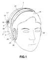
- Fig. 1 is a perspective view showing a sound collector according to the present invention mounted on a human head.
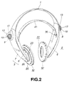
- Fig. 2 is a perspective view showing the sound collector according to the present invention removed from the human head.
- Fig. 3 is an exploded perspective view of the aforementioned sound collector viewed from its back.
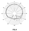
- Fig. 4 shows a sound collection characteristic of a microphone unit used in the sound collector according to the present invention.
- Fig. 5 is a block circuit diagram of the sound collector according to the present invention.
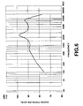
- Fig. 6 shows a sound pressure frequency characteristic of a loud speaker unit according to the present invention.
- the sound collector according to the present invention includes a head band 1 curved along the external configuration of a human head H.
- This head band 1 is made from a thin plate-shaped synthetic resin body which can be elastically displaced or a leaf spring.
- the head band 1 made from a leaf spring is coated with a coating material made from a synthetic resin or the like.
- each of these hunger blocks consists of a hunger body 6 and a cover member 7 which are connected to each other into a unitary block.
- the hunger block 6 includes a container block 5 which has a sufficient space for containing a printed circuit board 4 and other electronic components.
- the cover member 7 covers an opening of the hunger body 6.
- first and the second hunger blocks 2 and 3 there are provided a first microphone unit 8 and a second microphone unit 9, respectively.
- these first and second microphone units 8 and 9 are provided in the first and the second hunger blocks 2 and 3, respectively, so as to be positioned in the vicinity of the ears when the sound collector according to the present invention is mounted on the human head H.
- the first and second microphone units 8 and 9 are attached to the outer side of the connection portion of the first and second hunger blocks 2 and 3 to the head band 1.
- the second microphone unit 9 is placed on a microphone support plate 12 provided in a microphone mounting portion 11 formed on the outer side of the cover member 7 constituting the second hunger block 3.
- the second microphone unit 9 is supported by a microphone holder 13 to be mounted on the microphone mounting portion 11.
- the second microphone unit 9 is fitted into an elastic member 14 of cylindrical shape and via this elastic member 14 fitted into a fitting convex 12a formed on the microphone support plate 12, so as to be positioned in such a manner that when the sound collector according to the present invention is mounted on a human head, a sound collecting plane 9a faces the front of the head.
- the elastic member 14 also has a dumping function so that a vibration transmitted via the head band 1 and the second hunger block 3 will not be transmitted to the second microphone unit 9.
- a microphone stopper plate 15 is provided at the inside of the microphone holder 13.
- the second microphone unit 9 is fitted into the microphone support plate 12 so as to define the mounting direction and pressed to be supported by the microphone stopper plate 15.
- the second microphone unit 9 is positioned and mounted on the second hunger block 3.
- an opening 17 is provided at the front side of the microphone holder so as to oppose to the sound collecting plane 9a of the second microphone unit 9 mounted on the second hunger block 3, and a metal mesh is provided at a position to oppose the opening 17 of this microphone holder 13.
- a rear opening 18 is provided at the rear side of this microphone holder 13. This rear opening 18 is provided with a metal mesh 20 so as to prevent intrusion of dusts into the microphone holder 13.
- the first microphone unit 8 has a configuration which is right-to-left symmetrical to the configuration of the second microphone unit 9, and is mounted on the first hunger block 3.
- an external connection cord 21 is introduced through a cord pull-out hole 22 into the hunger body 6 to be connected to a microphone amplifier constituted on a printed circuit board 4 provided within the hunger body 6 of the second hunger block 3.
- the connection cord 21 pulled out from the first microphone unit 8 provided in the first hunger block 2 is introduced through the head band 1 and pulled out at the second hunger block 3 to be connected to the printed circuit board 4.
- first and the second hunger blocks 2 and 3 there are supported a first housing 24 and a second housing 25 containing a first loud speaker unit 22 and a second loud speaker unit 23, respectively. That is, these first and second housings 24 and 25 are arranged so as to face inside of the curved head band 1 so as to oppose each other and are pivotally fixed to the tip ends of the first and the second hunger blocks 2 and 3, so as to be supported in a rotatable state around a pivot 26.
- Fig. 3 shows the first loud speaker unit 22 disassembled, and the second loud speaker unit 23 has a configuration which is right-to-left symmetric to the configuration of the first loud speaker unit 22.
- Each of the first and the second loud speaker units 22 and 23 has a sound emitting plate 27 toward the front of the housings 24 and 25, and contains a magnetic circuit block 28 fitted in the housings 24, 25.
- a magnetic circuit 28 between the first and the second loud speaker units 22 and 23 is provided with acoustic components 29, 30 made from a material having a certain acoustic resistance such as urethane foam.
- a speaker screen 31 is provided at the front of the first and the second housings 24 and 25 so as to cover the sound emitting plane 27 of the first and the second loud speaker units 22 and 23.
- This speaker screen 31 is made from an urethane foam or the like having air permeability and serves to protect a diaphragm positioned at the sound emitting plane 27 of the first and the second loud speaker units 22 and 23 as well as to prevent intrusion of dusts into the first and the second loud speaker units 22 and 23.
- ear pads 32 facing the right and left ears, respectively, to cover the auricles when the sound collector is mounted on the human head H.
- Each of the ear pads 32 is made from a soft material such as urethane foam having a sound absorbing effect and shaped into a ring shape which is attached to the auricle contact surface of the first and the second housings 24, 25, so as to surround the sound emitting plane 27 of the first and the second loud speaker units 22 and 23.
- the soft material constituting the ear pads 32 is covered by an external cover made from a synthetic leather.
- the auricles are covered by the ear pads 32 so as to cut off or attenuate of an external sound coming into the auricles.
- the first hunger block 2 includes a battery container 35 for containing a battery D serving as a power source for driving the first and the second microphone units 8, 9 and the first and the second loud speaker units 22, 23.
- This battery container 35 has an interior to receive the battery D and has a cover 36 at its opening to be opened and closed.
- the battery D contained in the battery container 35 supplies electric power through a connection cord extending through the head band 1 to the first and the second microphone units 8, 9 and the first and the second loud speaker units 22, 23.
- the second hunger block 3 includes a power switch 37, power display block 38 made from a light emitting element such as a light emitting diode, and a volume adjusting Knob 39 for adjusting outputs of the first and the second microphone units 8, 9.
- a suspender 41 bridging the first and the second hunger blocks 2 and 3.
- This suspender 41 is attached so as to be extended and contracted between the first and the second hunger blocks 2 and 3, so that the suspender sits on the user's head in a stable mounting state.
- the first and the second microphone units 8 and 9 are positioned in the vicinity of the auricles with the sound collecting planes 9a facing forward from the head.
- a sound signal collected by the first and the second microphone units 8 and 9 is amplified by microphone amplifier 45 and 46 constituted on a printed circuit board and supplied via volumes 48, 49 for adjusting an output of a sound signal, to power amplifiers 50, 51 so as to be amplified by these power amplifiers 50, 51 for supply to the first and the second loud speaker units 22, 23 so as to drive the first and the second loud speaker units 22, 23.
- a reproduced sound emitted from the first and the second loud speaker units 22 and 23 when driven, is emitted to areas defined by the ear pads 32 and introduced into the auricles to be heard.
- the microphone amplifiers 45, 46 for amplification of a sound signal from the first and the second microphone units 8, 9 to be supplied to the first and the second loud speaker units 22, 23, amplify a sound signal of a frequency band in the vicinity of approximately 2 kHz to 3 kHz and attenuate a sound signal of a frequency band of approximately 50 Hz or below. Because the microphone amplifier 45, 46 have such an amplification function, the first and the second loud speaker units 22, 23 have a sound pressure frequency characteristic as shown in Fig.
- a stress is posed on a sound pressure level of a frequency band in the vicinity of approximately 2 to 3 kHz, i.e., the human voice frequency band, while suppressing a sound pressure level of a frequency band of 500 Hz or below such as a noise from an air conditioner or a motor drive sound.
- the sound collector according to the present invention includes the first and the second microphone unit for collecting an external sound through the head band mounted on a user's head, and the first and the second loud speaker unit for amplifying the sound collected by these microphone units and emitting the amplified sound. This enables to hear an external sound at an increased level by absorbing a difference in hearing ability and surely hear a desired sound.
- the ear pads provided at the auricle contact surface of the housings containing the first and the second loud speaker units enables to cut off a noise coming directly into the auricles, thus enabling to surely hear a desired sound without being affected by a noise.
Landscapes
- Physics & Mathematics (AREA)
- Engineering & Computer Science (AREA)
- Acoustics & Sound (AREA)
- Signal Processing (AREA)
- Details Of Audible-Bandwidth Transducers (AREA)
- Obtaining Desirable Characteristics In Audible-Bandwidth Transducers (AREA)
- Headphones And Earphones (AREA)
Applications Claiming Priority (2)
| Application Number | Priority Date | Filing Date | Title |
|---|---|---|---|
| JP329377/97 | 1997-07-31 | ||
| JP9329377A JPH1155777A (ja) | 1997-07-31 | 1997-07-31 | 集音器 |
Publications (1)
| Publication Number | Publication Date |
|---|---|
| EP0895439A2 true EP0895439A2 (de) | 1999-02-03 |
Family
ID=18220770
Family Applications (1)
| Application Number | Title | Priority Date | Filing Date |
|---|---|---|---|
| EP98306082A Withdrawn EP0895439A2 (de) | 1997-07-31 | 1998-07-30 | Schallaufnahmevorrichtung |
Country Status (4)
| Country | Link |
|---|---|
| US (1) | US5987147A (de) |
| EP (1) | EP0895439A2 (de) |
| JP (1) | JPH1155777A (de) |
| KR (1) | KR19990014214A (de) |
Cited By (5)
| Publication number | Priority date | Publication date | Assignee | Title |
|---|---|---|---|---|
| EP1587342A3 (de) * | 2004-03-29 | 2006-11-15 | Bose Corporation | Kopfhörer mit aktiver Rauschverminderung |
| EP1921889A1 (de) | 2006-11-10 | 2008-05-14 | Sony Corporation | Kopfhörer und Ohrpolster |
| GB2455141A (en) * | 2007-11-30 | 2009-06-03 | David John Kaminski | Earphone optionally providing sound to the environment |
| FR2988490A1 (fr) * | 2012-03-22 | 2013-09-27 | Thales Sa | Serre-tete modulaire pour pilote |
| WO2017155708A1 (en) * | 2016-03-08 | 2017-09-14 | Bose Corporation | Compliant constrained headband spring |
Families Citing this family (32)
| Publication number | Priority date | Publication date | Assignee | Title |
|---|---|---|---|---|
| JP2000059876A (ja) * | 1998-08-13 | 2000-02-25 | Sony Corp | 音響装置およびヘッドホン |
| US6668064B1 (en) * | 1999-07-06 | 2003-12-23 | Chung Yu Lin | Earphone without impulse noise and surrounding blockade |
| US6259796B1 (en) * | 1999-07-06 | 2001-07-10 | Chung-Yu Lin | Earpiece without impulse and high frequency noise |
| FR2817434A1 (fr) * | 2000-11-24 | 2002-05-31 | Churchill Trading | Perfectionnement aux combines, notamment telephoniques |
| USD457512S1 (en) | 2001-06-29 | 2002-05-21 | Sony Corporation | Headphone |
| USD457874S1 (en) | 2001-06-29 | 2002-05-28 | Sony Corporation | Headphone |
| US6847725B1 (en) * | 2002-12-16 | 2005-01-25 | Sandra J. Neuman | Radio, infrared, and audio assistive listening device |
| USD491163S1 (en) | 2002-12-20 | 2004-06-08 | Bose Corporation | Headset |
| USD484868S1 (en) | 2003-02-11 | 2004-01-06 | Sony Corporation | Headphone |
| US7903833B2 (en) * | 2006-03-06 | 2011-03-08 | Hearing Enhancement Group | Headworn listening device and method |
| KR100809549B1 (ko) | 2006-08-10 | 2008-03-04 | (주)와이즈앤블루 | 보청기 겸용 무선 헤드셋 및 그 제어방법 |
| NZ549912A (en) * | 2006-09-14 | 2009-07-31 | Phitek Systems Ltd | Battery Door |
| US20090196443A1 (en) * | 2008-01-31 | 2009-08-06 | Merry Electronics Co., Ltd. | Wireless earphone system with hearing aid function |
| KR101248841B1 (ko) * | 2008-11-04 | 2013-03-29 | 크레신 주식회사 | 헤드폰 |
| KR100925183B1 (ko) * | 2008-12-19 | 2009-11-06 | 김병화 | 청취 장치 |
| JP5799650B2 (ja) * | 2011-08-11 | 2015-10-28 | ソニー株式会社 | ヘッドホン装置 |
| USD772193S1 (en) * | 2014-10-13 | 2016-11-22 | Gibson Brands, Inc. | Headphones |
| USD766206S1 (en) * | 2015-05-28 | 2016-09-13 | Plantronics, Inc. | Headband for a headset or headphone |
| USD766207S1 (en) * | 2015-05-28 | 2016-09-13 | Plantronics, Inc. | Communications headset or headphone |
| USD766208S1 (en) * | 2015-05-28 | 2016-09-13 | Plantronics, Inc. | Communications headset or headphone |
| WO2017070261A1 (en) * | 2015-10-20 | 2017-04-27 | Alwin Co., Ltd. | Sound receiver and personal audio system having same |
| US10986431B2 (en) * | 2017-10-07 | 2021-04-20 | Point Source Audio, Inc. | Wearable microphone housing with built-in redundancy |
| US10893370B1 (en) | 2018-01-05 | 2021-01-12 | Texas Institute Of Science, Inc. | System and method for aiding hearing |
| US11128963B1 (en) | 2018-01-05 | 2021-09-21 | Texas Institute Of Science, Inc. | Hearing aid and method for use of same |
| US11153694B1 (en) | 2018-01-05 | 2021-10-19 | Texas Institute Of Science, Inc. | Hearing aid and method for use of same |
| JP2021510287A (ja) * | 2018-01-05 | 2021-04-15 | オラー、ラスロ | 補聴器及びその使用方法 |
| US10880658B1 (en) | 2018-01-05 | 2020-12-29 | Texas Institute Of Science, Inc. | Hearing aid and method for use of same |
| US11095992B2 (en) * | 2018-01-05 | 2021-08-17 | Texas Institute Of Science, Inc. | Hearing aid and method for use of same |
| US10993047B2 (en) | 2018-01-05 | 2021-04-27 | Texas Institute Of Science, Inc. | System and method for aiding hearing |
| US11102589B2 (en) * | 2018-01-05 | 2021-08-24 | Texas Institute Of Science, Inc. | Hearing aid and method for use of same |
| US12108220B1 (en) | 2024-03-12 | 2024-10-01 | Laslo Olah | System for aiding hearing and method for use of same |
| US12262179B1 (en) | 2024-03-12 | 2025-03-25 | Laslo Olah | Audiogram, system for aiding hearing, and method for use of same |
Family Cites Families (3)
| Publication number | Priority date | Publication date | Assignee | Title |
|---|---|---|---|---|
| US3306991A (en) * | 1963-06-04 | 1967-02-28 | Homer J Wood | Protective hearing aid |
| US5495534A (en) * | 1990-01-19 | 1996-02-27 | Sony Corporation | Audio signal reproducing apparatus |
| US5764778A (en) * | 1995-06-07 | 1998-06-09 | Sensimetrics Corporation | Hearing aid headset having an array of microphones |
-
1997
- 1997-07-31 JP JP9329377A patent/JPH1155777A/ja not_active Withdrawn
-
1998
- 1998-07-27 KR KR1019980030178A patent/KR19990014214A/ko not_active Withdrawn
- 1998-07-29 US US09/124,045 patent/US5987147A/en not_active Expired - Fee Related
- 1998-07-30 EP EP98306082A patent/EP0895439A2/de not_active Withdrawn
Cited By (11)
| Publication number | Priority date | Publication date | Assignee | Title |
|---|---|---|---|---|
| EP1587342A3 (de) * | 2004-03-29 | 2006-11-15 | Bose Corporation | Kopfhörer mit aktiver Rauschverminderung |
| US7412070B2 (en) | 2004-03-29 | 2008-08-12 | Bose Corporation | Headphoning |
| US7970159B2 (en) | 2004-03-29 | 2011-06-28 | Bose Corporation | Headphoning |
| EP1921889A1 (de) | 2006-11-10 | 2008-05-14 | Sony Corporation | Kopfhörer und Ohrpolster |
| US8150090B2 (en) | 2006-11-10 | 2012-04-03 | Sony Corporation | Headphone and ear pad |
| GB2455141A (en) * | 2007-11-30 | 2009-06-03 | David John Kaminski | Earphone optionally providing sound to the environment |
| FR2988490A1 (fr) * | 2012-03-22 | 2013-09-27 | Thales Sa | Serre-tete modulaire pour pilote |
| WO2017155708A1 (en) * | 2016-03-08 | 2017-09-14 | Bose Corporation | Compliant constrained headband spring |
| US9883288B2 (en) | 2016-03-08 | 2018-01-30 | Bose Corporation | Compliant constrained headband spring |
| CN109076287A (zh) * | 2016-03-08 | 2018-12-21 | 伯斯有限公司 | 柔性约束头带弹簧 |
| US10178476B2 (en) | 2016-03-08 | 2019-01-08 | Bose Corporation | Compliant constrained headband spring |
Also Published As
| Publication number | Publication date |
|---|---|
| US5987147A (en) | 1999-11-16 |
| KR19990014214A (ko) | 1999-02-25 |
| JPH1155777A (ja) | 1999-02-26 |
Similar Documents
| Publication | Publication Date | Title |
|---|---|---|
| US5987147A (en) | Sound collector | |
| US20230007386A1 (en) | Modular headphone system | |
| EP0589623B1 (de) | Kopfhörer | |
| CA1049134A (en) | Stereo microphone apparatus | |
| JP3038243B2 (ja) | 音響透過性イヤホン | |
| US9924261B2 (en) | Ear defender with concha simulator | |
| US5402497A (en) | Headphone apparatus for reducing circumference noise | |
| US6603863B1 (en) | Headphone apparatus for providing dynamic sound with vibrations and method therefor | |
| MY134555A (en) | Earphone | |
| JPS61103455A (ja) | 防毒マスク | |
| JP2002515197A (ja) | めがね取り付け具付イヤホン | |
| US11503399B2 (en) | Replaceable mesh in portable electronic devices | |
| JPH07115695A (ja) | イヤホン装置 | |
| US3258533A (en) | Ear-insert microphone | |
| US3830334A (en) | Speaker attachment for automobile radios and the like | |
| US20090154738A1 (en) | Mixable earphone-microphone device with sound attenuation | |
| CN111988696B (zh) | 耳机 | |
| US8045742B2 (en) | Audio headphone provided with device to prevent audio feedback | |
| JPH10200977A (ja) | スピーカ装置 | |
| JP3413693B2 (ja) | ヘッドホン装置 | |
| JP2019121896A (ja) | 首掛け型スピーカー装置 | |
| JPS6031350Y2 (ja) | 収音再生機器システム | |
| JPS644398B2 (de) | ||
| JPS6379500A (ja) | 電気音響変換器 | |
| JP2019121898A (ja) | スピーカー装置 |
Legal Events
| Date | Code | Title | Description |
|---|---|---|---|
| PUAI | Public reference made under article 153(3) epc to a published international application that has entered the european phase |
Free format text: ORIGINAL CODE: 0009012 |
|
| AK | Designated contracting states |
Kind code of ref document: A2 Designated state(s): AT BE CH CY DE DK ES FI FR GB GR IE IT LI LU MC NL PT SE |
|
| AX | Request for extension of the european patent |
Free format text: AL;LT;LV;MK;RO;SI |
|
| STAA | Information on the status of an ep patent application or granted ep patent |
Free format text: STATUS: THE APPLICATION IS DEEMED TO BE WITHDRAWN |
|
| 18D | Application deemed to be withdrawn |
Effective date: 20030201 |