EP0895403B1 - Vorrichtung zur Korrektur von Nichtlinearitäten eines Abtasters in einem Bilderzeugungsgerät - Google Patents
Vorrichtung zur Korrektur von Nichtlinearitäten eines Abtasters in einem Bilderzeugungsgerät Download PDFInfo
- Publication number
- EP0895403B1 EP0895403B1 EP98305505A EP98305505A EP0895403B1 EP 0895403 B1 EP0895403 B1 EP 0895403B1 EP 98305505 A EP98305505 A EP 98305505A EP 98305505 A EP98305505 A EP 98305505A EP 0895403 B1 EP0895403 B1 EP 0895403B1
- Authority
- EP
- European Patent Office
- Prior art keywords
- lut
- start signal
- scanning start
- address
- linearity
- Prior art date
- Legal status (The legal status is an assumption and is not a legal conclusion. Google has not performed a legal analysis and makes no representation as to the accuracy of the status listed.)
- Expired - Lifetime
Links
Images


Classifications
-
- H—ELECTRICITY
- H04—ELECTRIC COMMUNICATION TECHNIQUE
- H04N—PICTORIAL COMMUNICATION, e.g. TELEVISION
- H04N1/00—Scanning, transmission or reproduction of documents or the like, e.g. facsimile transmission; Details thereof
- H04N1/40—Picture signal circuits
-
- H—ELECTRICITY
- H04—ELECTRIC COMMUNICATION TECHNIQUE
- H04N—PICTORIAL COMMUNICATION, e.g. TELEVISION
- H04N1/00—Scanning, transmission or reproduction of documents or the like, e.g. facsimile transmission; Details thereof
- H04N1/04—Scanning arrangements, i.e. arrangements for the displacement of active reading or reproducing elements relative to the original or reproducing medium, or vice versa
- H04N1/047—Detection, control or error compensation of scanning velocity or position
-
- H—ELECTRICITY
- H04—ELECTRIC COMMUNICATION TECHNIQUE
- H04N—PICTORIAL COMMUNICATION, e.g. TELEVISION
- H04N1/00—Scanning, transmission or reproduction of documents or the like, e.g. facsimile transmission; Details thereof
- H04N1/04—Scanning arrangements, i.e. arrangements for the displacement of active reading or reproducing elements relative to the original or reproducing medium, or vice versa
- H04N1/12—Scanning arrangements, i.e. arrangements for the displacement of active reading or reproducing elements relative to the original or reproducing medium, or vice versa using the sheet-feed movement or the medium-advance or the drum-rotation movement as the slow scanning component, e.g. arrangements for the main-scanning
-
- H—ELECTRICITY
- H04—ELECTRIC COMMUNICATION TECHNIQUE
- H04N—PICTORIAL COMMUNICATION, e.g. TELEVISION
- H04N2201/00—Indexing scheme relating to scanning, transmission or reproduction of documents or the like, and to details thereof
- H04N2201/024—Indexing scheme relating to scanning, transmission or reproduction of documents or the like, and to details thereof deleted
- H04N2201/02406—Arrangements for positioning elements within a head
- H04N2201/02439—Positioning method
-
- H—ELECTRICITY
- H04—ELECTRIC COMMUNICATION TECHNIQUE
- H04N—PICTORIAL COMMUNICATION, e.g. TELEVISION
- H04N2201/00—Indexing scheme relating to scanning, transmission or reproduction of documents or the like, and to details thereof
- H04N2201/04—Scanning arrangements
- H04N2201/047—Detection, control or error compensation of scanning velocity or position
- H04N2201/04701—Detection of scanning velocity or position
- H04N2201/0471—Detection of scanning velocity or position using dedicated detectors
-
- H—ELECTRICITY
- H04—ELECTRIC COMMUNICATION TECHNIQUE
- H04N—PICTORIAL COMMUNICATION, e.g. TELEVISION
- H04N2201/00—Indexing scheme relating to scanning, transmission or reproduction of documents or the like, and to details thereof
- H04N2201/04—Scanning arrangements
- H04N2201/047—Detection, control or error compensation of scanning velocity or position
- H04N2201/04701—Detection of scanning velocity or position
- H04N2201/04715—Detection of scanning velocity or position by detecting marks or the like, e.g. slits
- H04N2201/04722—Detection of scanning velocity or position by detecting marks or the like, e.g. slits on a photoconductive drum or belt
-
- H—ELECTRICITY
- H04—ELECTRIC COMMUNICATION TECHNIQUE
- H04N—PICTORIAL COMMUNICATION, e.g. TELEVISION
- H04N2201/00—Indexing scheme relating to scanning, transmission or reproduction of documents or the like, and to details thereof
- H04N2201/04—Scanning arrangements
- H04N2201/047—Detection, control or error compensation of scanning velocity or position
- H04N2201/04753—Control or error compensation of scanning position or velocity
- H04N2201/04758—Control or error compensation of scanning position or velocity by controlling the position of the scanned image area
- H04N2201/04767—Control or error compensation of scanning position or velocity by controlling the position of the scanned image area by controlling the timing of the signals, e.g. by controlling the frequency o phase of the pixel clock
- H04N2201/04768—Controlling the frequency of the signals
- H04N2201/04775—Controlling the frequency of the signals using a counter
-
- H—ELECTRICITY
- H04—ELECTRIC COMMUNICATION TECHNIQUE
- H04N—PICTORIAL COMMUNICATION, e.g. TELEVISION
- H04N2201/00—Indexing scheme relating to scanning, transmission or reproduction of documents or the like, and to details thereof
- H04N2201/04—Scanning arrangements
- H04N2201/047—Detection, control or error compensation of scanning velocity or position
- H04N2201/04753—Control or error compensation of scanning position or velocity
- H04N2201/04793—Control or error compensation of scanning position or velocity using stored control or compensation data, e.g. previously measured data
-
- H—ELECTRICITY
- H04—ELECTRIC COMMUNICATION TECHNIQUE
- H04N—PICTORIAL COMMUNICATION, e.g. TELEVISION
- H04N2201/00—Indexing scheme relating to scanning, transmission or reproduction of documents or the like, and to details thereof
- H04N2201/04—Scanning arrangements
- H04N2201/047—Detection, control or error compensation of scanning velocity or position
- H04N2201/04753—Control or error compensation of scanning position or velocity
- H04N2201/04794—Varying the control or compensation during the scan, e.g. using continuous feedback or from line to line
Definitions
- the present invention relates to an image forming apparatus, and more particularly, to a device for correcting the non-linearity of a scanner without reference to the pulse width of a varying scanning position signal.
- a laser scanning unit scans a photosensitive belt to form a latent image. Then, a developing device supplies a liquid toner to the photosensitive belt, and develops the latent image to form a toner image, and the toner image is printed on a paper sheet by transfer and fixing devices. In a series of processes, while the correction of scanner non-linearity begins synchronously at the rising edge of a scanning start signal, the scanning is performed.
- correction of the non-linearity of the scanner comprises the steps of: detecting a predetermined portion of the photosensitive belt, and generating the scanning start signal; and generating a synchronizing signal corresponding to the scanning start signal wherein the frequency of the generated synchronizing signal is used as the image input frequency of the scanner.
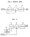
- FIG. 1 shows a block diagram illustrating the structure of a conventional device for correcting the non-linearity of a scanner.
- a conventional device for correcting the non-linearity of the scanner comprises: a counter 100 which is reset by the input scanning start signal and counts the scanning start signals; a LUT (look-up table) 110 which is enabled by the scanning start signal, recognizes an output of the counter 100 as an address, and outputs the look-up table information corresponding to the address in the form of digital data; and a converter 120 which outputs a clock signal having a frequency corresponding to the digital data output from the LUT 110.
- the clock signal is input to a laser scanning unit (not shown), and thus the scanning can be carried out.
- a pattern for generating a synchronizing signal is formed at a portion of a photosensitive belt, and the device is synchronously operated by the scanning start signal which is generated by sensing the pattern.
- the pulse width of the scanning start signal may be abnormally deformed due to vibrations from sources such as the photosensitive belt, a starting point for correcting non-linearity may be imprecisely determined.
- FIGS. 2A and 2B show timing diagrams for describing the problem of the conventional device for correcting the non-linearity of the scanner.
- SOS scanning start signal
- the counter 100 is reset at the falling edge of the scanning start signal, and generates a corresponding address signal, for example, address 1, address 2, address 3, and so on.
- the corresponding digital data such as LUT information 1, LUT information 2, LUT information 3, stored in the LUT 110 is output according to the address signal, and the converter 120 outputs a synchronizing signal having frequencies such as f 1 , f 2 , f 3 , and so on corresponding to the digital data. While the counter 100 outputs address signals, the above procedure is repeated.
- the address signal output from the counter 100, the digital data output from the LUT110, and the synchronizing signal output from the converter 120 are delayed when a scanning start signal (SOS max ) of a maximized pulse width is generated because of the vibration of the photosensitive belt.
- the pulse width of a scanning start signal may be abnormally narrowed or widened due to mechanical errors caused by vibrations from sources such as the photosensitive belt, and accordingly the correct starting position is imprecisely determined. Consequently, there is a problem in that the correction of the non-linearity of the scanner cannot be performed precisely in the conventional device.
- a device for correcting the non-linearity of a scanner comprising: a reset pulse generator for generating a reset pulse with a predetermined pulse width in synchronization with a scanning start signal generated in accordance with an input photosensitive belt sensing signal; an address generator for outputting an address by being reset by the reset pulse; a LUT (look-up table) enabled by the scanning start signal, for receiving an address from the address generator and for outputting information corresponding to the address in the form of digital data; and a converter for outputting a synchronizing signal with a frequency corresponding to the digital data from the LUT.
- the information stored in the LUT is made by measuring the scanner linearity with the same condition that a scanning start signal of a preset pulse width was generated.
- the reset pulse generator generates a pulse having the same pulse width as the pulse width of the scanning start signal used when the information stored in the LUT was made, and generates the reset pulse in synchronization with the rising edge of the scanning start signal.
- the LUT is enabled in synchronization with the falling edge of the scanning start signal, and the address generator is a counter.
- Figure 3 shows a block diagram illustrating constituent elements of a preferred device for correcting the non-linearity of a scanner.
- the correcting device comprises a reset pulse generator 300, a counter 310, a LUT (look-up table) 320 and a converter 330, and generates a clock signal in response to a scanning start signal input.
- the scanning start signal is input into the reset pulse generator 300 and the LUT 320, to let the reset pulse generator 300 output a reset pulse of a predetermined pulse width, and enable the LUT 320.
- LUT information is already stored in the LUT 320.
- the LUT information is made by measuring the scanner linearity with the same condition that a scanning start signal of a preset pulse width was generated.
- the reset pulse width output from the reset pulse generator 300 has no relation to the pulse width of the scanning start signal, and is the same pulse width as used when the LUT information was made by a physical mechanism for synchronizing with the scanning start signal.
- the counter 310 which is input with the reset pulse from the reset pulse generator 300 counts the reset pulses, and the counted value is input into the LUT 320 and serves as an address.
- the output of the counter 310 is input into the LUT 320 as an address signal, the LUT 320 does not operate until the falling edge of the scanning start signal.
- the LUT 320 is enabled at the falling edge of the scanning start signal, and outputs the LUT information in the form of digital data.
- the output digital data is the data stored in the LUT 320 by measuring the linearity of the scanner in advance.
- the converter 330 generates a clock signal having a frequency corresponding to the digital data output from the LUT 320.
- the clock signal output from the converter 330 as a signal for correcting the non-linearity of the scanner is input into a laser scanning unit. Since the laser scanning unit scans a photosensitive belt according to the input clock signal, the non-linearity is simultaneously corrected during scanning. At this time, though the pulse width of the scanning start signal, which serves as a reference signal of the device for correcting the non-linearity is varied, the counter 310 is operated by a pulse having a pulse width having no relation to the pulse width of the scanning start signal, and the LUT 320 is enabled at the falling edge of the scanning start signal. Accordingly, the correction of the non-linearity can be precisely accomplished.
- Figure 4 shows signal waveforms in accordance with the operation of the device of Figure 3.
- the counter 310 is reset and operates at the falling edge of the reset pulse (P) generated in the reset pulse generator 300. Therefore, though the falling edge of the scanning start signal (SOS max ) does not yet occur, the counter 310 outputs the counted value, i.e., the address signal. Meanwhile, the LUT 320 is enabled at the falling edge of the scanning start signal.
- the LUT 320 outputs LUT information 3, i.e., the LUT information corresponding to address 3, in the form of digital data. Then, the converter 330 converts the digital data into a clock pulse with frequency f 3 and outputs the clock pulse. Further, when the counter 310 outputs address 4 after outputting address 3, the LUT 320 outputs LUT information 4, i.e., the LUT information corresponding to address 4, in the form of digital data. Consequently, the clock pulse with frequency f 4 is input into the laser scanning unit, and the non-linearity of the scanner is corrected.
Landscapes
- Engineering & Computer Science (AREA)
- Multimedia (AREA)
- Signal Processing (AREA)
- Facsimile Scanning Arrangements (AREA)
- Laser Beam Printer (AREA)
- Facsimile Image Signal Circuits (AREA)
Claims (6)
- Vorrichtung zum Korrigieren der Nichtlinearität eines Abtasters, umfassend:gekennzeichnet durch:einen Adressengenerator (310) zum Ausgeben einer Adresse;eine Nachschlagetabelle LUT (320) zum Empfangen einer Adresse aus dem Adressengenerator (310) und zum Ausgeben einer der Adresse entsprechenden Information in der Form von digitalen Daten; undeinen Wandler (330) zum Ausgeben eines Synchronisationssignals mit einer den digitalen Daten aus der LUT (320) entsprechenden Frequenz;die LUT durch das Abtaststartsignal aktiviert wird.einen Rücksetzimpulsgenerator (300) zum Erzeugen eines Rücksetzimpulses mit einer vorbestimmten Impulsbreite synchron mit seinem Abtaststartsignal, das gemäß einem Eingangserfassungssignal aus einem photoempfindlichen Band erzeugt wird;wobei der Adressengenerator durch den Rücksetzimpuls zurückgesetzt wird; und
- Vorrichtung nach Anspruch 1, wobei die in der LUT (320) gespeicherte Information durch Messen der Abtasterlinearität unter Verwendung eines nominellen Abtaststartsignals mit einer voreingestellten Impulsbreite erstellt wird.
- Vorrichtung nach Anspruch 2, wobei der Rücksetzimpulsgenerator einen Impuls (P) mit derselben Impulsbreite wie der Impulsbreite des nominellen Abtaststartsignals erzeugt, das bei der Erstellung der in der LUT gespeicherten Information verwendet wurde.
- Vorrichtung nach einem der Ansprüche 1 bis 3, wobei der Rücksetzimpulsgenerator (300) den Rücksetzimpuls synchron mit der ansteigenden Flanke des Abtaststartsignals (SOS) erzeugt.
- Vorrichtung nach einem der Ansprüche 1 bis 4, wobei die LUT (320) synchron mit der abfallenden Flanke des Abtaststartsignals (SOS) aktiviert wird.
- Vorrichtung nach einem der Ansprüche 1 bis 5, wobei der Adressengenerator (310) ein Zähler ist.
Applications Claiming Priority (2)
| Application Number | Priority Date | Filing Date | Title |
|---|---|---|---|
| KR9736180 | 1997-07-30 | ||
| KR1019970036180A KR100234305B1 (ko) | 1997-07-30 | 1997-07-30 | 화상 형성 장치의 스캐너 비선형성 보정 장치 |
Publications (3)
| Publication Number | Publication Date |
|---|---|
| EP0895403A2 EP0895403A2 (de) | 1999-02-03 |
| EP0895403A3 EP0895403A3 (de) | 1999-05-06 |
| EP0895403B1 true EP0895403B1 (de) | 2004-03-03 |
Family
ID=19516292
Family Applications (1)
| Application Number | Title | Priority Date | Filing Date |
|---|---|---|---|
| EP98305505A Expired - Lifetime EP0895403B1 (de) | 1997-07-30 | 1998-07-10 | Vorrichtung zur Korrektur von Nichtlinearitäten eines Abtasters in einem Bilderzeugungsgerät |
Country Status (5)
| Country | Link |
|---|---|
| US (1) | US6128029A (de) |
| EP (1) | EP0895403B1 (de) |
| KR (1) | KR100234305B1 (de) |
| CN (1) | CN1100677C (de) |
| DE (1) | DE69822049T2 (de) |
Families Citing this family (3)
| Publication number | Priority date | Publication date | Assignee | Title |
|---|---|---|---|---|
| US6376091B1 (en) * | 2000-08-29 | 2002-04-23 | Amorphous Technologies International | Article including a composite of unstabilized zirconium oxide particles in a metallic matrix, and its preparation |
| US7639407B2 (en) * | 2004-03-24 | 2009-12-29 | Lexmark International, Inc. | Systems for performing laser beam linearity correction and algorithms and methods for generating linearity correction tables from data stored in an optical scanner |
| KR100811351B1 (ko) * | 2004-03-24 | 2008-03-10 | 로무 가부시키가이샤 | 유기 el 구동 회로 및 이것을 이용하는 유기 el 표시장치 |
Family Cites Families (10)
| Publication number | Priority date | Publication date | Assignee | Title |
|---|---|---|---|---|
| US4067760A (en) * | 1976-03-24 | 1978-01-10 | General Foods Corporation | Gate control for printed web scanner |
| US4571623A (en) * | 1984-01-26 | 1986-02-18 | Minnesota Mining And Manufacturing Company | Data clocking circuitry |
| AT392536B (de) * | 1984-07-06 | 1991-04-25 | R S F Elektronik Ohg Rechtsfor | Lineares, inkrementales messsystem |
| JPH07105857B2 (ja) * | 1989-03-16 | 1995-11-13 | 富士ゼロックス株式会社 | 画像読取装置の自己診断システム |
| JP2667590B2 (ja) * | 1991-03-12 | 1997-10-27 | 三田工業株式会社 | レーザビームを用いた画像形成装置の水平同期信号生成装置 |
| US5453851A (en) * | 1992-07-31 | 1995-09-26 | E. I. Du Pont De Nemours And Company | Error reduction methods in scanning systems |
| US5510877A (en) * | 1994-04-20 | 1996-04-23 | Xerox Corporation | Method and apparatus for lateral registration control in color printing |
| US5815726A (en) * | 1994-11-04 | 1998-09-29 | Altera Corporation | Coarse-grained look-up table architecture |
| JPH08163363A (ja) * | 1994-12-12 | 1996-06-21 | Fuji Xerox Co Ltd | 画像形成装置 |
| WO1997019550A1 (en) * | 1995-11-17 | 1997-05-29 | Imation Corp. | System for registration of color separation images on a photoconductor belt |
-
1997
- 1997-07-30 KR KR1019970036180A patent/KR100234305B1/ko not_active Expired - Fee Related
-
1998
- 1998-07-08 CN CN98115458A patent/CN1100677C/zh not_active Expired - Fee Related
- 1998-07-10 EP EP98305505A patent/EP0895403B1/de not_active Expired - Lifetime
- 1998-07-10 US US09/113,554 patent/US6128029A/en not_active Expired - Fee Related
- 1998-07-10 DE DE69822049T patent/DE69822049T2/de not_active Expired - Fee Related
Also Published As
| Publication number | Publication date |
|---|---|
| DE69822049D1 (de) | 2004-04-08 |
| CN1223935A (zh) | 1999-07-28 |
| CN1100677C (zh) | 2003-02-05 |
| EP0895403A3 (de) | 1999-05-06 |
| DE69822049T2 (de) | 2004-12-30 |
| KR100234305B1 (ko) | 1999-12-15 |
| EP0895403A2 (de) | 1999-02-03 |
| US6128029A (en) | 2000-10-03 |
| KR19990012703A (ko) | 1999-02-25 |
Similar Documents
| Publication | Publication Date | Title |
|---|---|---|
| US6208367B1 (en) | Light beam scanning apparatus and image forming apparatus | |
| US4962981A (en) | Optical scanner | |
| US20070030548A1 (en) | Apparatus for generating pulse-modulated signal | |
| KR100199431B1 (ko) | 화소클록 발생장치 | |
| JP4440137B2 (ja) | クロック信号生成回路、光走査装置及び画像形成装置 | |
| EP0895403B1 (de) | Vorrichtung zur Korrektur von Nichtlinearitäten eines Abtasters in einem Bilderzeugungsgerät | |
| JP2020188389A (ja) | 画像形成装置 | |
| EP1133056B1 (de) | Vorrichtung zum Generieren eines Taktsignals | |
| JP2001246777A (ja) | 印刷システムの画像データ送出方式および印刷装置 | |
| EP0568255A1 (de) | Bilderzeugungsgerät | |
| JP5696003B2 (ja) | 画像形成装置 | |
| US6791722B1 (en) | Light beam scanning apparatus and image forming apparatus | |
| EP1244289A2 (de) | Laserabtaster und diesen verwendendes Kopiergerät | |
| JP2010068228A (ja) | 画像読取装置、及び画像形成装置 | |
| JPH05227396A (ja) | 画像記録装置 | |
| KR0125458B1 (ko) | 전자사진 현상방식 프린터의 화소 크기 조절장치 | |
| EP1619871A2 (de) | Videotakterzeugungsgerät und -Verfahren | |
| JP3624060B2 (ja) | パルスモータ駆動装置 | |
| JP2536838B2 (ja) | 水平同期信号出力装置 | |
| JP2580398B2 (ja) | プリンタの印字位置補正処理方式 | |
| JPH08265532A (ja) | 画像形成装置 | |
| JP2002337389A (ja) | 印字制御装置 | |
| JP2006305879A (ja) | 画像形成装置及び画像形成方法 | |
| JP2000263841A (ja) | 画像形成装置及び画像形成方法 | |
| JP2005225119A (ja) | カラー画像形成装置 |
Legal Events
| Date | Code | Title | Description |
|---|---|---|---|
| PUAI | Public reference made under article 153(3) epc to a published international application that has entered the european phase |
Free format text: ORIGINAL CODE: 0009012 |
|
| 17P | Request for examination filed |
Effective date: 19980729 |
|
| AK | Designated contracting states |
Kind code of ref document: A2 Designated state(s): DE FR GB |
|
| AX | Request for extension of the european patent |
Free format text: AL;LT;LV;MK;RO;SI |
|
| PUAL | Search report despatched |
Free format text: ORIGINAL CODE: 0009013 |
|
| AK | Designated contracting states |
Kind code of ref document: A3 Designated state(s): AT BE CH CY DE DK ES FI FR GB GR IE IT LI LU MC NL PT SE |
|
| AX | Request for extension of the european patent |
Free format text: AL;LT;LV;MK;RO;SI |
|
| AKX | Designation fees paid |
Free format text: DE FR GB |
|
| GRAP | Despatch of communication of intention to grant a patent |
Free format text: ORIGINAL CODE: EPIDOSNIGR1 |
|
| GRAS | Grant fee paid |
Free format text: ORIGINAL CODE: EPIDOSNIGR3 |
|
| GRAA | (expected) grant |
Free format text: ORIGINAL CODE: 0009210 |
|
| AK | Designated contracting states |
Kind code of ref document: B1 Designated state(s): DE FR GB |
|
| REG | Reference to a national code |
Ref country code: GB Ref legal event code: FG4D |
|
| REF | Corresponds to: |
Ref document number: 69822049 Country of ref document: DE Date of ref document: 20040408 Kind code of ref document: P |
|
| ET | Fr: translation filed | ||
| PLBE | No opposition filed within time limit |
Free format text: ORIGINAL CODE: 0009261 |
|
| STAA | Information on the status of an ep patent application or granted ep patent |
Free format text: STATUS: NO OPPOSITION FILED WITHIN TIME LIMIT |
|
| 26N | No opposition filed |
Effective date: 20041206 |
|
| PGFP | Annual fee paid to national office [announced via postgrant information from national office to epo] |
Ref country code: DE Payment date: 20070705 Year of fee payment: 10 |
|
| PGFP | Annual fee paid to national office [announced via postgrant information from national office to epo] |
Ref country code: GB Payment date: 20070704 Year of fee payment: 10 |
|
| PGFP | Annual fee paid to national office [announced via postgrant information from national office to epo] |
Ref country code: FR Payment date: 20070710 Year of fee payment: 10 |
|
| GBPC | Gb: european patent ceased through non-payment of renewal fee |
Effective date: 20080710 |
|
| PG25 | Lapsed in a contracting state [announced via postgrant information from national office to epo] |
Ref country code: DE Free format text: LAPSE BECAUSE OF NON-PAYMENT OF DUE FEES Effective date: 20090203 |
|
| REG | Reference to a national code |
Ref country code: FR Ref legal event code: ST Effective date: 20090331 |
|
| PG25 | Lapsed in a contracting state [announced via postgrant information from national office to epo] |
Ref country code: GB Free format text: LAPSE BECAUSE OF NON-PAYMENT OF DUE FEES Effective date: 20080710 |
|
| PG25 | Lapsed in a contracting state [announced via postgrant information from national office to epo] |
Ref country code: FR Free format text: LAPSE BECAUSE OF NON-PAYMENT OF DUE FEES Effective date: 20080731 |