EP0895322A1 - Gas laser - Google Patents
Gas laser Download PDFInfo
- Publication number
- EP0895322A1 EP0895322A1 EP97916644A EP97916644A EP0895322A1 EP 0895322 A1 EP0895322 A1 EP 0895322A1 EP 97916644 A EP97916644 A EP 97916644A EP 97916644 A EP97916644 A EP 97916644A EP 0895322 A1 EP0895322 A1 EP 0895322A1
- Authority
- EP
- European Patent Office
- Prior art keywords
- rotational speed
- fan
- drive motor
- temperature
- torque
- Prior art date
- Legal status (The legal status is an assumption and is not a legal conclusion. Google has not performed a legal analysis and makes no representation as to the accuracy of the status listed.)
- Withdrawn
Links
- 239000000498 cooling water Substances 0.000 claims abstract description 13
- 238000009529 body temperature measurement Methods 0.000 claims description 4
- 238000001816 cooling Methods 0.000 claims description 4
- 238000005259 measurement Methods 0.000 claims description 4
- 230000000087 stabilizing effect Effects 0.000 claims description 2
- 239000007789 gas Substances 0.000 description 69
- 238000010586 diagram Methods 0.000 description 9
- 229910052736 halogen Inorganic materials 0.000 description 7
- 150000002367 halogens Chemical class 0.000 description 7
- 239000011553 magnetic fluid Substances 0.000 description 7
- 230000010355 oscillation Effects 0.000 description 7
- 230000008859 change Effects 0.000 description 5
- 238000000034 method Methods 0.000 description 5
- 230000000694 effects Effects 0.000 description 4
- 230000002093 peripheral effect Effects 0.000 description 3
- 230000000630 rising effect Effects 0.000 description 3
- 230000008901 benefit Effects 0.000 description 2
- 150000004820 halides Chemical class 0.000 description 2
- 238000010438 heat treatment Methods 0.000 description 2
- 230000002459 sustained effect Effects 0.000 description 2
- 230000007704 transition Effects 0.000 description 2
- 230000015556 catabolic process Effects 0.000 description 1
- 230000007423 decrease Effects 0.000 description 1
- 238000006731 degradation reaction Methods 0.000 description 1
- 238000009795 derivation Methods 0.000 description 1
- 230000005284 excitation Effects 0.000 description 1
- 230000001747 exhibiting effect Effects 0.000 description 1
- 230000004907 flux Effects 0.000 description 1
- 239000004519 grease Substances 0.000 description 1
- 239000000463 material Substances 0.000 description 1
- 230000007246 mechanism Effects 0.000 description 1
- 239000000203 mixture Substances 0.000 description 1
- 238000012544 monitoring process Methods 0.000 description 1
- 230000003287 optical effect Effects 0.000 description 1
- 238000005457 optimization Methods 0.000 description 1
Images


Classifications
-
- H—ELECTRICITY
- H01—ELECTRIC ELEMENTS
- H01S—DEVICES USING THE PROCESS OF LIGHT AMPLIFICATION BY STIMULATED EMISSION OF RADIATION [LASER] TO AMPLIFY OR GENERATE LIGHT; DEVICES USING STIMULATED EMISSION OF ELECTROMAGNETIC RADIATION IN WAVE RANGES OTHER THAN OPTICAL
- H01S3/00—Lasers, i.e. devices using stimulated emission of electromagnetic radiation in the infrared, visible or ultraviolet wave range
- H01S3/02—Constructional details
- H01S3/03—Constructional details of gas laser discharge tubes
- H01S3/036—Means for obtaining or maintaining the desired gas pressure within the tube, e.g. by gettering, replenishing; Means for circulating the gas, e.g. for equalising the pressure within the tube
Definitions
- This invention concerns a gas laser apparatus that realizes smaller motor volume and a motor drive system that can cope with loss torque (rotational resistance) in magnetic seals used in a shaft seal unit for a fan drive motor that circulates gas between electrodes in a laser chamber that generates a purple laser beam by the application of a high voltage (20 to 30 kV) between the electrodes under conditions wherein an inactive gas and a halogen gas are mixed.
- rare gases and halogen gases are used as the laser medium gas, whereupon it is necessary to keep these halogen gases and other highly reactive gases from reacting with the material of which the laser chamber is made, and thus to prevent the degradation of the laser medium gas.
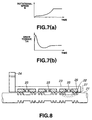
- Fig. 8 is a diagram of one example of magnetic seals.
- the magnetic seal comprises a rotation shaft 21, magnetic fluid 22, housing 23, attachment flange 24, magnets 25, and pole pieces 26. Stages 27 similar to labyrinth seals are provided in the rotation shaft 21.
- the magnetic circuits are formed as closed circuits by a magnet 25, pole piece 26 (N pole), rotation shaft 21, pole piece 26 (S pole), and magnet 25, wherewith the magnetic flux is concentrated in the radial gap between each of the stages 27and pole pieces.
- the magnetic fluid 22 is interposed in these radial gaps, forming O rings, and thereby effecting gas seals.
- Each stage of these magnetic seals is capable of holding a pressure differential of about 0.2 atmosphere. Thus a high-pressure gas seal can be effected by using multiple stages, reducing leakage to nothing.
- a laser device in which a differential pressure cell is provided at back stage of the magnetic seal, an inner pressure difference between the laser chamber and the differential pressure cell is made small compared to a difference between the inner pressure of the laser chamber and the atmospheric pressure, so that the number of stages of the magnetic seal is reduced, by which the magnetic seal is compact-sized and the number of the stages is reduced, thus the loss torque is also reduced.
- control is effected such that, after the gas circulating fan is started at a lower pressure than the laser medium gas pressure during laser oscillation, the laser medium gas pressure for laser oscillation is set, and the circulating fan is stopped whenever the laser medium gas pressure rises above a certain pressure.
- magnetic seal loss torque is to be reduced by altering the structure of the magnetic seals by providing heating means or pressure-differential cells therein, wherefore the peripheral structure about the magnetic seals is made complex, and it becomes impossible to reduce the overall size of the gas laser apparatus or realize low power consumption.
- An object of the present invention is to eliminate the problems noted above, providing a gas laser apparatus wherewith the magnetic seal loss torque is lessened, and the size of the gas circulating fan drive motor is reduced, whereby the overall size of the gas laser apparatus can be made smaller and low power consumption can be realized, without altering the structure of the gas laser apparatus.
- a first invention is a gas laser apparatus including a fan for circulating laser medium gas; a fan drive motor for driving the fan; and magnetic seals for preventing leakage of the laser medium gas from a drive shaft of the fan drive motor, characterized in that the apparatus comprises control means for controlling a rotational speed of the fan drive motor, based on a rotational speed pattern for a predetermined elapsed time for stabilizing the fan drive motor at a prescribed steady rotational speed, within a prescribed amount of time and within a prescribed drive torque.
- a second invention is a gas laser apparatus including a fan for circulating laser medium gas; a fan drive motor for driving the fan; and magnetic seals for preventing leakage of the laser medium gas from a drive shaft of the fan drive motor, characterized in that the apparatus comprises: torque measurement means for measuring a drive torque of the fan drive motor; and control means for controlling a rotational speed of the fan drive motor, based on the drive torque measured by the torque measurement means, so as to stabilize the rotational speed at a steady prescribed speed within a prescribed amount of time and within a prescribed drive torque.
- a third invention is the gas laser apparatus in the second invention, characterized in that the gas laser apparatus further comprises: a cooling valve for controlling opening and closing of inflow and outflow of cooling water that cools the magnetic seals; temperature measurement means for measuring a temperature of the magnetic seals; and valve control means for controlling opening and closing of the cooling valve, based on the temperature measured by the temperature measurement means, in order to maintain the temperature of the magnetic seals within a prescribed range.
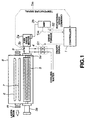
- Fig. 1 is a diagram depicting the configuration of a gas laser apparatus that is a second embodiment of the present invention.
- a laser chamber 8 is filled with a laser medium gas made up of a rare gas and a halogen gas, at prescribed pressure and compositional ratio, and a purple laser beam is output from a partially transparent mirror m by discharge excitation with discharge electrodes 6 and 7.
- a gas circulating fan 5 is comprised inside the laser chamber 8 for injecting the laser medium gas that is to be excited between the discharge electrodes 6 and 7.
- This gas circulating fan 5 is connected to a fan drive motor 2a that turns the gas circulating fan 5 via a drive shaft 5a.
- This fan drive motor 2a is in turn connected to a motor drive amp 2b.
- the laser medium gas is sealed inside the laser chamber 8 by a magnetic seal unit 3b so that it does not leak, and the other end of the drive shaft 5a is sealed by a magnetic seal unit 3a.
- Cooling water flows about the periphery of the magnetic seal unit 3b to prevent the temperature of the magnetic seal unit 3b from rising.
- the inflow and outflow of this cooling water are controlled by the opening and closing of a valve 4.
- the magnetic seal unit 3b comprises a temperature sensor 9 for detecting the temperature of the magnetic seal unit 3b.
- a controller 1 effects on/off control to open and close the valve 4 by an on/off signal S1, based on a temperature signal Tm detected by the temperature sensor 9.
- the controller 1 based on a drive torque signal ⁇ m from the motor drive amp 2b, outputs a rotational speed command signal S2 to the motor drive amp 2b, and thus controls the rotation of the fan drive motor 2a.
- Fig. 2 is a flowchart indicating drive control procedures for controlling a fan drive motor 2a by a controller 1.
- the controller 1 outputs an on/off signal S1 instructing the valve 4 to turn off (step 101), thus allowing the temperature of the magnetic seal unit 3b to rise.
- the controller 1 next outputs a rotational speed command signal S2 for a predetermined initial rotational speed Ns (cf. Fig. 3(b)) to the motor drive amp 2b (step 102).
- a rotational speed command signal S2 for a predetermined initial rotational speed Ns (cf. Fig. 3(b)) to the motor drive amp 2b (step 102).
- the drive torque of the fan drive motor 2a immediately after rotation starts, increases very rapidly under the influence of the initial loss torque (rotational resistance at low temperature) of the magnetic seal unit 3b.
- the initial rotational speed Ns is set so that it will fall within the rated torque ⁇ t of the fan drive motor 2a.
- the controller 1 then monitors the drive torque signal ⁇ m from the monitor drive amp 2b, and effects control to maintain the initial rotational speed Ns until the drive torque ⁇ m becomes smaller than the drive torque ⁇ s predetermined as a constant (No in step 103).
- the controller 1 When the drive torque signal ⁇ m becomes smaller than the predetermined drive torque ⁇ s (Yes in step 103), the controller 1 outputs a rotational speed command signal S2 to the motor drive amp 2b to gradually increase the rotational speed of the fan drive motor 2a (step 104). When the rotational speed indicated by the rotational speed command signal S2 reaches a prescribed rotational Speed Nc (Yes in step 105), the controller 1 concludes that laser medium gas circulation will thereafter be effected normally, whereupon a laser oscillation preparation-complete signal is output from either a display unit or notification unit not shown in the drawing.
- the controller 1 meanwhile, in parallel operations, after outputting an on/off signal S1 instructing the valve 4 to turn off (close) in step 101, monitors the temperature signal Tm from the temperature sensor 9, determines whether or not a prescribed threshold temperature T1 has been exceeded (step 111), outputs an on/off signal S1 to the valve 4 instructing the valve 4 to turn on (open) (step 112), causes cooling water to flow in, and thus effects control to lower the temperature of the magnetic seal unit 3b.
- the controller 1 also continuously monitors the temperature signal Tm from the temperature sensor 9 to determine whether or not the temperature has fallen below a threshold temperature T2 (step 113).
- the controller 1 When the temperature falls below the threshold temperature T2, the controller 1 outputs an on/off signal S1 to the valve 4 directing it to turn off (close) (step 114), thereby stopping the inflow of cooling water, preventing the temperature of the magnetic seal unit 3b from declining, and allowing the temperature to rise due to the rotational friction of the magnetic fluid inside the magnetic seal unit 3b.
- the controller 1 moves to step 111 and repeats the temperature control described above, thereby maintaining the temperature of the magnetic seal unit 3b between the threshold temperature T1 and the threshold temperature T2.
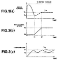
- the charts in Fig. 3(a) and (b), respectively, are plots of the drive torque ⁇ m and change in rotational speed over time for the fan drive motor 2a.
- a rotational speed command signal S2 for the initial rotational speed Ns is input from the controller 1 to the motor drive amp 2b, the fan drive motor 2a, through the motor drive amp 2b, immediately reaches the initial rotational speed Ns, and maintains that initial rotational speed Ns until time t1.
- the drive torque ⁇ m during the time period up to that time t1 increases very rapidly as rotation commences due to the rotational resistance of the magnetic fluid in the magnetic seal unit 3b, but the rotational resistance decreases due to the rise in temperature associated with the rotational resistance, whereupon the prescribed drive torque ⁇ s is attained at point t1.
- the controller 1 causes the rotational speed to gradually rise from the rotational speed Ns in what is, here, a linear manner.
- the drive torque ⁇ m also gradually increases, and, when it reaches the prescribed rotational speed Nc, the rotational speed is maintained at this prescribed rotational speed Nc.
- the drive torque ⁇ m also, from this time t2 onward, is maintained at a constant torque ⁇ c.
- the chart in Fig. 3(c) is a plot of temperature changes in the magnetic seal unit 3b.
- the controller 1 at the time rotation starts, sets the valve 4 in the off (open) position, whereupon the temperature of the magnetic seal unit 3b rises in conjunction with the rotation (at rotational speed Ns) of the fan drive motor 2a. Subsequently, when the temperature of the magnetic seal unit 3b reaches the prescribed threshold temperature T1, the valve 4 is turned on (open), cooling water flows into the periphery about the magnetic seal unit 3b, and the temperature of the magnetic seal unit 3b declines. When the temperature declines as far as the prescribed threshold temperature T2, the valve 4 is turned off (closed), the cooling water is stopped, and the temperature of the magnetic seal unit 3b rises. Such temperature control is conducted repeatedly, whereby the temperature of the magnetic seal unit 3b is maintained between the threshold temperature T1 and the threshold temperature T2.
- the drive torque ⁇ m and temperature Tm are monitored, and both rotational speed control for the fan drive motor 2a and magnetic seal unit 3b temperature control are performed, independently and in parallel.
- the fan can be driven by a fan drive motor having an allowable load capacity of approximately one third.
- the size of the fan drive motor can be reduced, without in any way altering the structure of the magnetic seal unit 3b, making it possible to implement a gas laser apparatus the overall size of which is made smaller.
- control of the rise in the rotational speed from time t1 to time t2 in the first embodiment, as described above, is such, moreover, that the rotational speed is raised linearly, but it need not be so limited.
- This control may instead be performed so that, for example, the rotational speed is raised quadratically from Ns to Nc.
- the temperature sensor 9 is provided in the magnetic seal unit 3b, and the temperature in the magnetic seal unit 3b is controlled by opening and closing the valve 4 based on the temperature signal Tm from the temperature sensor 9.
- Tm temperature signal
- a second embodiment is next described.
- a rotational speed pattern relative to the passage of time is found such that the peak value of the fan drive motor torque is minimized until a constant rotational speed, such as the rotational speed Nc in the first embodiment, is reached.
- the fan drive motor is run on the basis of the rotational speed pattern so found.
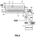
- Fig. 4 is a diagram depicting the configuration of a gas laser apparatus that is the second embodiment of the present invention.
- this gas laser apparatus exhibits roughly the same configuration as the gas laser apparatus diagrammed in Fig. 1.
- the controller does not effect control by monitoring the temperature signal Tm from the temperature sensor 9 or the drive torque ⁇ m from the motor drive amp.
- the gas laser apparatus based on this second embodiment is such that a laser chamber 18 is filled with a laser medium gas made up of rare gases and halogen gases, at a prescribed pressure and composition, and an ultraviolet laser beam is output from a partially transparent mirror mm by discharges excited with discharge electrodes 16 and 17.
- the interior of the laser chamber 18 is provided with a gas circulating fan 15 for introducing the laser medium gas to be excited between the discharge electrodes 16 and 17.
- This gas circulating fan 15 is connected to a fan drive motor 12a that turns the gas circulating 15 via a drive shaft 15a.
- the fan drive motor 12a is connected to a motor drive amp 12b.
- a seal is made between the fan drive motor 12a and the laser chamber 18 by seal unit 13b so that the laser medium gas inside the laser chamber 18 does not leak.
- the other end of the drive shaft 15a is sealed with magnetic zeal unit 13a.
- Cooling water flows about the periphery of the magnetic seal unit 13b to prevent the temperature of the magnetic seal unit 13b from rising.
- the in-flow and out-flow of this cooling water is controlled by opening and closing valve 14.
- a controller 11 on/off-controls the opening and closing of the valve 14 by an on/off signal S11.
- the controller 11 also outputs a rotational speed command signal S12 to the motor drive amp 12b and controls the rotation of the fan drive motor 12a, based on a predetermined rotational speed pattern over time.
- the predetermined rotational speed pattern here, as noted earlier, is a pattern wherewith is minimized the peak value of the drive torque until the rotational speed of the fan drive motor 12a reaches a constant rotational speed.
- the time interval until the fan drive motor 12a reaches a constant rotational speed is usually determined so that it matches the warm-up time (approximately 10 minutes) for the thyratron used as the switching device for generating discharges between the discharge electrodes 16 and 17. Accordingly, it is necessary to determine a rotational speed pattern wherewith the drive torque peak value is minimized and the desired constant rotational speed is reached during that determined time interval. Finding this rotational speed pattern is a kind of optimization problem, and it is very difficult to derive an exact solution therefor.
- Rotational speeds are determined, respectively, at which the peak load torque value as diagrammed in Fig. 5(a) and the load torque value at constant rotational speed as diagrammed in Fig. 5(c) roughly match.
- the rotational speed at start-up is set at c1 and the rotational speed at constant rotational speed is set at c2.
- a rotational speed pattern such as that plotted in Fig. 6(b) is produced.
- the period from time t11 to time t12 is determined as the period during which there is a transition from rotational speed c1 to rotational speed c2.
- the change in rotational speed during the transition from rotational speed c1 to rotational speed c2 is a linear change, but, as with the first embodiment, this may be some other rotational speed change.
- Time t11 here, is established as a time at which the peak value of the drive torque during start-up has been fully passed.
- the time interval to time t12 is a time period that at least includes the required time intervals, such as that required for thyratron warm-up, as mentioned earlier.
- the fan drive motor 12a that is capable of handling the load torque at constant rotational speed as the fan drive motor for the gas laser apparatus.
- the fan drive motor need only have approximately one third of the allowable torque capacity of a conventional fan drive motor on which no rotational speed control is performed. Thus not only can the fan drive motor be made smaller, but the overall gas laser apparatus can be made smaller, too.
- the controller 11 outputs the rotational speed pattern found, such as the rotational speed pattern plotted in Fig. 7(a), for example, as time passes, to the motor drive amp 12b, in the form of rotational speed command signals S12, whereupon the fan drive motor 12a is driven so as to follow this rotational speed pattern.
- the drive torque exhibits the change over time plotted in Fig. 7(a).
- the controller 11 moreover, turns the valve 14 on (open) with an on/off signal S11, simultaneously with start-up, causing cooling water to flow into the periphery of the magnetic seal unit 13b, and thus preventing the temperature of the magnetic seal unit 13b from rising.
- the rotational speed of the fan drive motor is controlled by the control means, particularly from start-up until constant speed is attained, whereupon the rotational speed of the fan drive motor is kept at a constant rotational speed within a prescribed time interval and within a prescribed drive torque [range]. Therefore, the fan drive motor can be made smaller, even without complexly modifying the magnetic seal peripheral structure, which is an advantage. It thus becomes possible to drive the fan with a fan drive motor having approximately one third the allowable load capacity of a conventional fan drive motor.
Landscapes
- Physics & Mathematics (AREA)
- Electromagnetism (AREA)
- Engineering & Computer Science (AREA)
- Plasma & Fusion (AREA)
- Optics & Photonics (AREA)
- Lasers (AREA)
Applications Claiming Priority (3)
| Application Number | Priority Date | Filing Date | Title |
|---|---|---|---|
| JP92646/96 | 1996-04-15 | ||
| JP9264696A JPH09283820A (ja) | 1996-04-15 | 1996-04-15 | ガスレーザ装置 |
| PCT/JP1997/001255 WO1997039502A1 (en) | 1996-04-15 | 1997-04-11 | Gas laser |
Publications (2)
| Publication Number | Publication Date |
|---|---|
| EP0895322A1 true EP0895322A1 (en) | 1999-02-03 |
| EP0895322A4 EP0895322A4 (enExample) | 1999-03-10 |
Family
ID=14060228
Family Applications (1)
| Application Number | Title | Priority Date | Filing Date |
|---|---|---|---|
| EP97916644A Withdrawn EP0895322A1 (en) | 1996-04-15 | 1997-04-11 | Gas laser |
Country Status (3)
| Country | Link |
|---|---|
| EP (1) | EP0895322A1 (enExample) |
| JP (1) | JPH09283820A (enExample) |
| WO (1) | WO1997039502A1 (enExample) |
Family Cites Families (5)
| Publication number | Priority date | Publication date | Assignee | Title |
|---|---|---|---|---|
| JPS62281484A (ja) * | 1986-05-30 | 1987-12-07 | Mitsubishi Electric Corp | レ−ザ発振装置 |
| JPS6353987A (ja) * | 1986-08-22 | 1988-03-08 | Mitsubishi Electric Corp | 回転導入端子 |
| JPS63184381A (ja) * | 1987-01-27 | 1988-07-29 | Toshiba Corp | ガスレ−ザ発振装置 |
| JPS63157966U (enExample) * | 1987-04-03 | 1988-10-17 | ||
| JPH0670265U (ja) * | 1993-03-10 | 1994-09-30 | 日新電機株式会社 | ガスレーザ装置 |
-
1996
- 1996-04-15 JP JP9264696A patent/JPH09283820A/ja active Pending
-
1997
- 1997-04-11 WO PCT/JP1997/001255 patent/WO1997039502A1/ja not_active Ceased
- 1997-04-11 EP EP97916644A patent/EP0895322A1/en not_active Withdrawn
Non-Patent Citations (2)
| Title |
|---|
| No further relevant documents disclosed * |
| See also references of WO9739502A1 * |
Also Published As
| Publication number | Publication date |
|---|---|
| JPH09283820A (ja) | 1997-10-31 |
| WO1997039502A1 (en) | 1997-10-23 |
| EP0895322A4 (enExample) | 1999-03-10 |
Similar Documents
| Publication | Publication Date | Title |
|---|---|---|
| US20110243177A1 (en) | Gas laser device | |
| US5770899A (en) | Linear motor | |
| JP2005090480A (ja) | 車両のエンジン冷却システム制御装置及び方法 | |
| CN103988378B (zh) | 激光振荡装置 | |
| EP0895322A1 (en) | Gas laser | |
| US3768035A (en) | Modular aerodynamic laser window | |
| US20030051485A1 (en) | Method and system for temperature regulation of a peltier element | |
| US20080304533A1 (en) | Startup method for gas laser unit and gas laser unit having startup function | |
| JPH0548190A (ja) | レーザアニール装置 | |
| JP2011049376A (ja) | レーザ加工機システム | |
| CN116316034B (zh) | 激光器系统及其控制方法和控制装置 | |
| JP6010152B2 (ja) | 送風機を備えるレーザ発振器 | |
| JP2821764B2 (ja) | 気体レーザ発振装置 | |
| EP4431222B1 (en) | Predictive cooling for a laser processing device | |
| JPH10229229A (ja) | 放電励起型ガスレーザ発振装置 | |
| JP2820939B2 (ja) | Ncレーザ装置 | |
| JPH09266342A (ja) | ガスレ−ザ発振器 | |
| JP5048999B2 (ja) | 工作機械の温度制御システム | |
| JP5494027B2 (ja) | レーザ発振装置 | |
| JP2504271B2 (ja) | レ―ザ発振装置 | |
| JP4107158B2 (ja) | レーザ発振装置およびレーザ加工機 | |
| JPH08330659A (ja) | ガスレーザ装置 | |
| JPH05327072A (ja) | 固体レーザ用冷却装置 | |
| JPS61203688A (ja) | ガス循環型レ−ザ発振装置 | |
| JP2682091B2 (ja) | ガス循環式レーザ発振器のガス制御方法 |
Legal Events
| Date | Code | Title | Description |
|---|---|---|---|
| PUAI | Public reference made under article 153(3) epc to a published international application that has entered the european phase |
Free format text: ORIGINAL CODE: 0009012 |
|
| 17P | Request for examination filed |
Effective date: 19981112 |
|
| AK | Designated contracting states |
Kind code of ref document: A1 Designated state(s): DE |
|
| A4 | Supplementary search report drawn up and despatched |
Effective date: 19990122 |
|
| AK | Designated contracting states |
Kind code of ref document: A4 Designated state(s): DE |
|
| STAA | Information on the status of an ep patent application or granted ep patent |
Free format text: STATUS: THE APPLICATION HAS BEEN WITHDRAWN |
|
| 18W | Application withdrawn |
Withdrawal date: 19990304 |